Introduction
In the recent years, as the rapid development of high-speed wireless communication systems, RF front-end modules are required to be compact, low cost and multi-functional. In this aspect, the balun filter is one of the promising circuit blocks to simultaneously maintain the function of a balun and the frequency selectivity of a bandpass filter (BPF). So far, a variety of balun filters have been successfully explored. Among them, a Low-Temperature Co-fired Ceramic technology (LTCC) technology has been used to construct a few compact balun filters with compact size [Reference Yeung and Wu1, Reference Xu, Zhang and Zhao2]. However, these balun BPFs suffer from complexity in geometry and high-cost in fabrication. Meanwhile, as an alternative method, the multi-layered balun BPFs with compact size and good filtering performance have been proposed in [Reference Zhang, Chen, Shi, Tang, Chu and Bao3, Reference Tang, Chen, Chu, Zhang, Yang and Bao4], but their complexity in geometry and design procedure has restricted them in practical application. The dielectric resonators in a metallic enclosure [Reference Chen, Li, Zhan, Qin, Shi and Bao5, Reference Chen, Zhan, Qin and Bao6] and substrate integrated waveguide resonators [Reference Wu, Guo, Mao and Yin7, Reference Hui, Feng and Che8] have been utilized to constitute a class of low-loss balun BPFs with good frequency selectivity and out-of-band rejection. Unfortunately, their operating bandwidth is extremely narrow. Balun filter in [Reference Xue, Shi and Chen9] based on coupled was reported, but the operational bandwidth is still narrow. The aforementioned technologies can only realize good balanced performance in amplitude and phase within a limited frequency range. Recently, some balun filters with good performance based on slot-line technologies have been proposed [Reference Huang, Wang, Hong and Wu10, Reference Chen, Zhu, Bu and Cheng11]. However, to the best of our knowledge, no synthesis approach has been presented so far toward the efficient design of this type of balun filters.
In this paper, a novel class of planar balun BPFs with intrinsic balanced performance in amplitude and phase over a wide frequency band is presented based on the inductive-coupled slot-line resonator (SLR). After its working principle and design approach are described, a prototype balun BPF is designed, fabricated and tested. Both simulated and measured results show good frequency selectivity, amplitude, and phase-balanced performance as predicted in theory.
Analysis working principle of intrinsic balanced performance
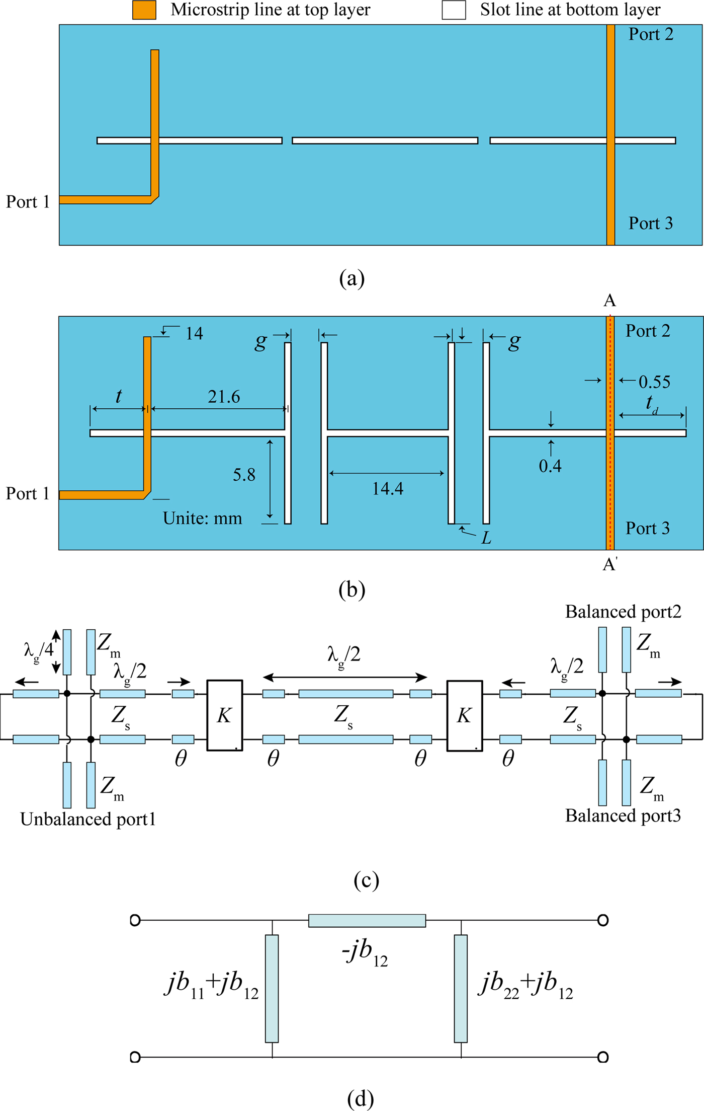
Figures 1(a) and 1(b) depict the geometries of the two proposed third-order balun BPF, namely, initial and improved balun BPFs. The first one shows the end-coupled SLR structure, and the coupling strength between two adjacent SLRs is not strong enough in design. The latter one with all the key parameters labeled can achieve a compact size and wide bandwidth. It consists of three λ g/2 anti-coupled SLRs, one unbalanced port, and one paired balanced port. Figure 1(c) gives its corresponding equivalent circuit model by excluding its input/output ports. In Fig. 1(b), the anti-paralleled coupled slotline is expressed as an equivalent K-inverters in Fig. 1(c) [Reference Sun and Zhu12]. Meanwhile, the first and third SLRs at each side are coupled to external ports via tapped-feeding. By transforming this circuit model to its associated π-network in Fig. 1(d), K-inverters’ values and their respective effective lengths can be extracted from the full-wave-simulated two-port S-parameters as follows [Reference Xue, Shi and Chen9]:
 $$\displaystyle{K \over {Z_s}} = \displaystyle{{{\bar b}_{12} \sin ( - (\theta /2))} \over {\sin ( - (\theta /2)) + {\bar b}_{11} \cos ( - (\theta /2))}},$$
 $$\theta = n\pi + \tan ^{ - 1}\left\{ {\displaystyle{{2({\bar b}_{11} + {\bar b}_{22} \vert \bar b \vert )} \over {1 + \bar b_{22}^2 - \bar b_{11}^2 - \vert \bar b \vert ^2}}} \right\},$$
where  $\bar b_{11} = b_{11}Z_s$,
 $\bar b_{22} = b_{22}Z_s$,
 $\bar b_{12} = b_{12}Z_s,$ and
 $\vert {\bar b} \vert = \vert \bar b \vert = \bar b_{11}^2 \bar b_{22}^2 - \bar b_{12}^2 $, Z s is the characteristic impedance of feeding lines at two external ports, respectively, and n is the non-negative integer.
Geometries and equivalent networks of the proposed balun bandpass filters (BPFs). (a) Initial balun BPF. (b) Improved balun BPF with strong coupling degree and compact size. (c) Network excluding input/output ports. (d) Equivalent π-network of K-inverter.
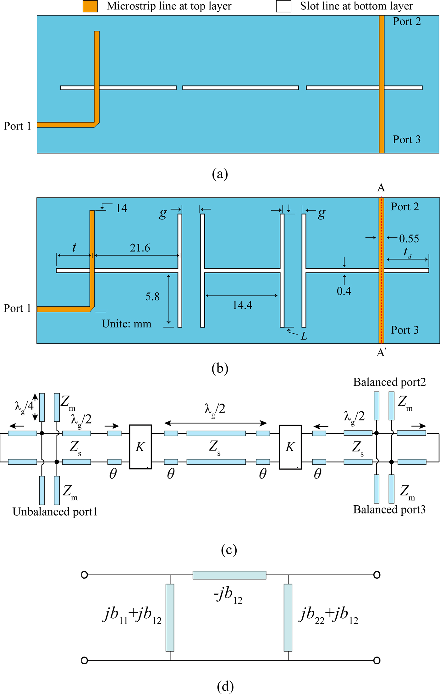
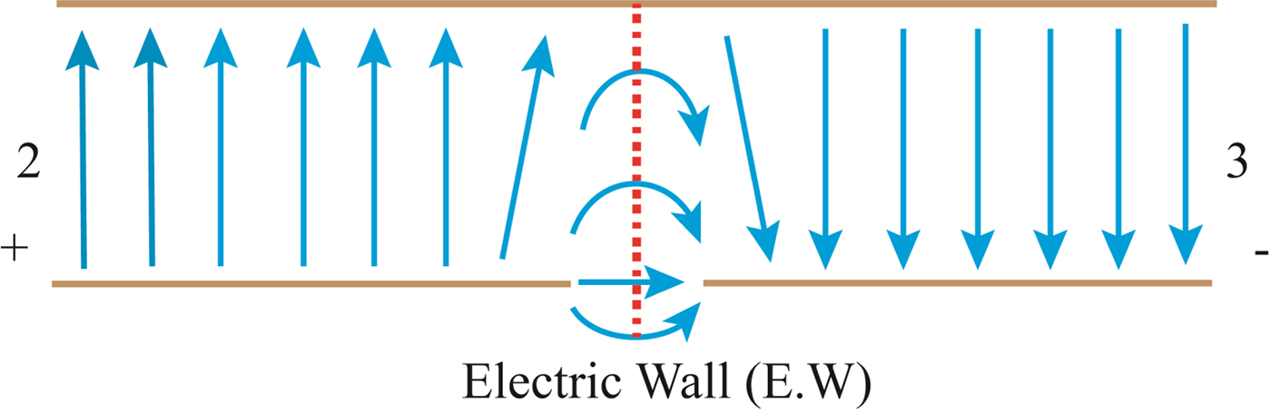
Figure 2 shows the cross-sectional view of the electric field distribution in the two-metal-layer structure at the location of plane indicated by the red dash line. The odd-symmetrical electric field in the slotline is excited by the unbalanced signal at port 1, so the symmetrical plane of the slotline represents an electric wall (E.W). To be well satisfied with this boundary condition, the electric fields must be identical in amplitude and opposite in phase, thus achieving the good transition from slot-line to the microstrip line. In this context, the intrinsic 180° phase difference and equal amplitude of the balanced signal at two output terminals can be achieved. In other words, the proposed balun BPF can intrinsically meet equations (2) and (3). Till now, the working principle of intrinsic balanced performance in amplitude and phase of the proposed balun BPFs in Figs 1(a) and 1(b) has been intuitively elaborated.
 $$ \vert S_{21} \vert = \vert S_{31} \vert, $$
 $$\left \vert {{\rm Phase}(S_{21}) - {\rm Phase}(S_{31})} \right \vert = 180{\rm ^\circ} {\rm.} $$
Cross-view of electric field transformation from the slotline at the center to the two balanced portions.

Balun filter on coupled SLRs
In order to validate our proposed technique, a third-order Chebyshev balun BPF at 2.2 GHz with a wide fractional bandwidth (FBW) of 30% and a return loss of 15 dB is designed and implemented. The normalized elements in its respective third-order lowpass prototype are found as g 0 = 1, g 1 = 1.119, g 2 = 1.15, g 3 = 1.119, and g 4 = 1 corresponding to the ripple level of 0.13954 dB. Based on the values of these elements, the geometrical parameters of this proposed balun BPF can be calculated so as to determine the required external quality factor and coupling coefficient as [Reference Sun and Zhu12, Reference Hong and Lancaster13]
 $$Q_s = Q_d = \displaystyle{{g_{_0} \hskip-3pt \cdot \hskip-1.5pt g_{_1}} \over {FBW}} = \displaystyle{{g_{_3} \hskip-3pt \cdot \hskip-1.5pt g_{_4}} \over {FBW}} = 3.730,$$
 $$M_{12} = M_{23} = \displaystyle{{FBW} \over {\sqrt {g_{_1} \hskip-3pt \cdot \hskip-1.5pt g_{_2}}}} = \displaystyle{{FBW} \over {\sqrt {g_{_2} \hskip-3pt \cdot \hskip-1.5pt g_{_3}}}} = 0.263.$$
The normalized K-inverter and the coupling coefficient are mutually related as [Reference Sun and Zhu12]:
 $$\displaystyle{K \over {Z_s}} = \displaystyle{{\pi M_{12}} \over 2} = \displaystyle{{\pi M_{23}} \over 2}.$$
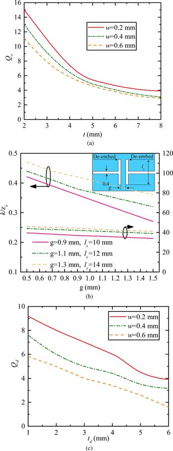
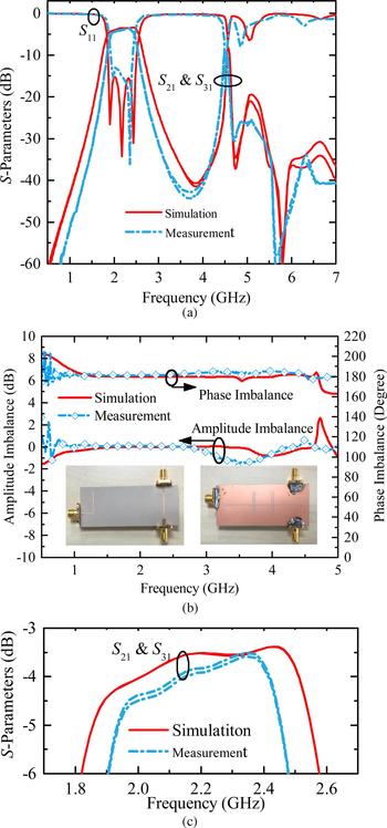
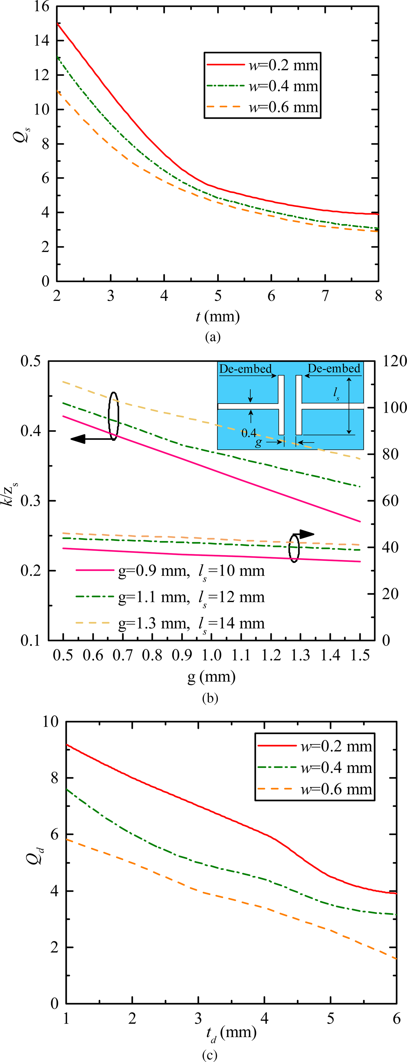
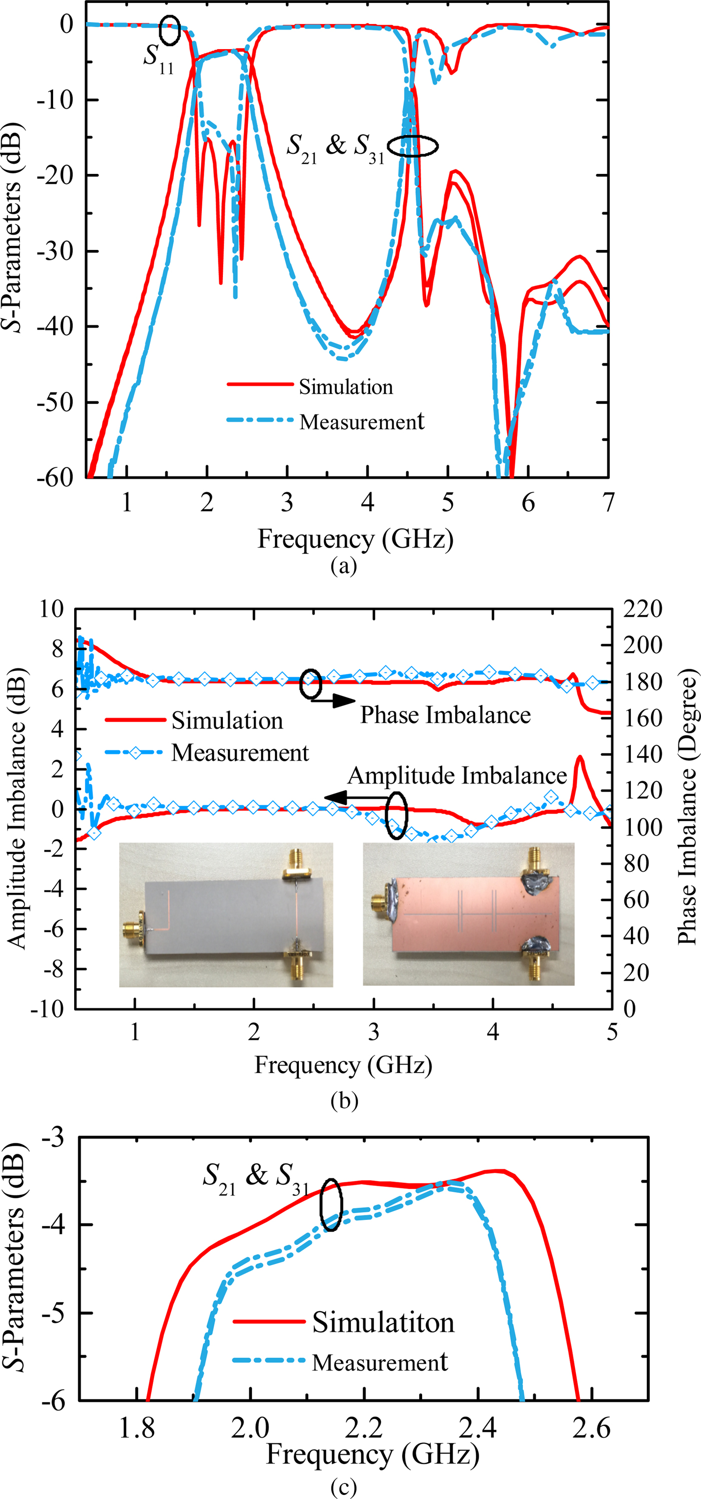
Figure 3(a) depicts the external quality factors as a function of the tapping position t and differential slot-line width of w, respectively. As t becomes small or the tapping position is moved from the center to the terminals of slotline, the external quality factor tends to fall off as illustrated in Fig. 3(a). Figure 3(b) shows the de-embedded normalized values of the K-inverter under the coupling length of L = 12.4. As the coupling gap g between anti-parallel-coupled slotlines increases under the fixed coupling length L, the relevant coupling degree is gradually weakened as shown in Fig. 3(b). Based on the above analysis and design, all the physical dimensions of the proposed balun BPF can be derived. Figure 1(b) depicts its final physical layout with all the labeled dimensions. Figure 4(b) shows its simulated amplitude and phase imbalances in a frequency range of 0–5.0 GHz. It is apparent that its amplitude and phase imbalances are both good over a frequency range of 1.5–3.5 GHz, thereby evidently validating the claimed intrinsic balanced performance in amplitude and phase over a wide frequency range in section “Analysis working principle of intrinsic balanced performance”. The simulated and measured IL is given in Fig. 4(c).
De-embedded coupling parameters. (a) External quality factor Q s. (b) Normalized K-inverter and electrical length under different coupling gaps and l s. (c) External quality factor Q d.
Results of the designed balun BPF. (a) Simulated and measured S-parameters. (b). Simulated and measured results in amplitude and phase imbalances. (c) Simulated and measured insertion losses.
Measured results and discussion
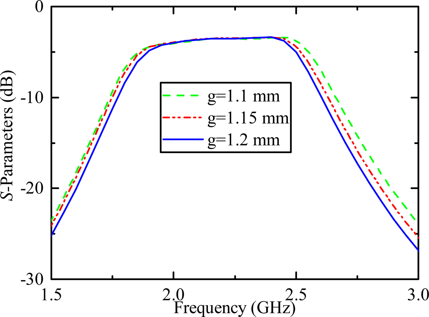
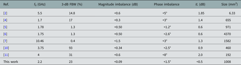
To further verify the predicted electrical performance, a third-order balun BPF prototype on three coupled LSRs is designed and implemented on the Rogers 6010 with a substrate thickness of 0.635 mm, the dielectric constant of 10.8 and loss tangent of 0.0023. The simulated results are derived from a commercial full-wave simulator, Ansoft HFSS, and the measured ones are obtained by using the four-port Vector Network Analyzer, R&S ZNB20. Figure 4(a) depicts the simulated and measured amplitude of the reflection and transmission coefficients of the balun BPF in Fig. 1(b), showing good agreement with each other. These results indicate that the implemented balun BPF operates at the central frequency of 2.26 GHz with a 3-dB FBW of 23%. The measured in-band return loss is better than 12.7 dB, and good agreement between the simulated and measured S-parameters is achieved over a wide frequency range up to 4.6 GHz. The measured 3-dB bandwidth is slightly lower than its simulated one. It might be mainly caused by unexpected fabrication tolerance, parasitic effect of slot-line thickness, and so on. As shown in Fig. 5, the operating bandwidth is progressively reduced as the inter-coupling gap g increases or the coupling strength between two SLRs decreases. Thereafter, we can draw a compressive conclusion that the discrepancy between the measured and simulated bandwidths is indeed mainly attributed to the tolerances in the manufacturing process. These unexpected tolerances may change the coupling between resonators, tapped feeding position, or width of SLR, etc. Nevertheless, three transmission poles have clearly emerged both in the simulated and measured results, thus demonstrating a third-order bandpass filtering performance. In addition, the first harmonic passband has been effectively suppressed to improve the out-of-band performance. As illustrated in Fig. 4(b), the proposed balun BPF has exhibited good balanced performance in both simulation and measurement, and it has an amplitude imbalance better than 0.09 dB and a phase imbalance better than 3° over a wideband frequency range. Moreover, various performances are tabulated in Table 1 with other reported counterparts for comparatively demonstrating the advantages of our proposed one. In addition, the power loss ( $1 - S_{11}^2 - S_{12}^2 - S_{13}^2 $) can be used to estimate the radiation loss, and our measured results show that it is equal to about 16% for our fabricated balun filter.
A set of tolerance analysis on different values of g.

Comparison with other reported wideband filter baluns

Measured results and discussion
In this paper, a balun BPF with good filtering response, intrinsic amplitude and phase balanced balun filter has been proposed and implemented on coupled SLRs. After its working principle is explained, a third-order balun BPF prototype is designed, fabricated and tested. The predicted bandpass filtering responses with intrinsic amplitude and phase balanced performance have been validated in the experiment over a wide frequency range.
Acknowledgements
This work is supported in part by University Research Grants (MYRG2017-00007-FST & CPG2017-00028-FST) from the University of Macau, and FDCT Research Grant (091/2016/A2) from the Science and Technology Development Fund of Macao, Macau SAR, China.
 Lin-Ping Feng received the M.E. degree from the University of Electronic Science and Technology of China (UESTC), Chengdu, China, in 2015. He is currently pursuing the Ph.D. degree in the University of Macau, Macau, China. His current research interests include filter, antennas, millimeter wave antenna, etc.
 Lei Zhu received the B.Eng. and M.Eng. degrees in Radio Engineering from Nanjing Institute of Technology (now Southeast University), Nanjing, China, in 1985 and 1988, respectively, and the Ph.D. degree in Electronic Engineering from the University of Electro-Communications, Tokyo, Japan, in 1993. He joined the Faculty of Science and Technology, the University of Macau in August 2013, where he has been a Distinguished Professor since December 2016. So far, he has published more than 280 journal papers (including more than 170 papers in IEEE Transactions/Letters/Magazine) and about 140 conference papers. His research interests include microwave circuits, guided-wave periodic structures, planar antennas, and computational electromagnetic techniques. Professor Zhu was the Associate Editors for IEEE Transactions o Microwave Theory and Techniques (2010–2013) and IEEE Microwave and Wireless Components Letters (2006–2012). He served as the members of IEEE MTT-S Fellow Evaluation Committee (2013–2015), and IEEE AP-S Fellows Committee (2015–2017). He was a General Chair of 2008 IEEE MTT-S International Microwave Workshop Series on the Art of Miniaturizing RF and Microwave Passive Components, Chengdu, China. He was the recipient of the 1997 Asia–Pacific Microwave Prize Award. He is the Fellow of IEEE.