Introduction
Electrochemical ceramic cells consist of ceramic ion-conducting materials for the electrolyte and mixed (ionic and electronic) conducting materials for the electrodes, and typically operate at 700–800°C. Because of such high-temperature operation, the cells can be highly efficient systems. However, high-temperature operation also leads to increased system cost and limited application. Thus, lowering the operating temperature of the cells is expected to solve such problems, and contribute to cost reduction and to widespread adoption of electrochemical devices (see the Introductory article in this issue).
Solid-oxide fuel cells (SOFCs) are examples of ceramic electrochemical cells that are expected to achieve this widespread adoption.Reference Minh1–Reference Mukhopadhyay, Mukhopadhyay, Sharma and Basu9 Because ceramics are structural materials, a variety of shapes (e.g., planar, tubular) and structures (e.g., electrode supported, electrolyte supported, metal supported) of SOFCs have been widely studied. For SOFC operation, high temperatures are needed in order to achieve a sufficient rate of oxygen ion diffusion and the oxygen dissociation reaction. In turn, SOFCs can utilize a hydrocarbon fuel directly or with a simple reforming reactor (for conversion to H2), with the help of high temperatures. This allows the design of simple SOFC systems. Recently, SOFCs have found application in portable power devices for consumer electronics from several watts, and in combined heat and power (CHP) systems for households and buildings up to several hundred kW.
Currently, studies of SOFCs mainly focus on improving the durability of the cell/stack/module for thermal and redox cycling in order to increase the service lifetime. Lowering the SOFC operating temperature also leads to an improvement in these factors, and allows a quick start-up of the system in addition to cost reduction. Typically, it is reported that the operating temperature of SOFCs can be lowered by utilizing ultrathin electrolytes or introducing new materials with higher ionic conductivity.Reference Tsuchiya, Lai and Ramanathan10–Reference Hibino, Hashimoto, Suzuki and Sano18
This article shows the effectiveness of designing cell structure through the use of microtubular cells to reduce the operating temperature to 650°C or lower while using conventional materials. High-performance anode-supported microtubular and micro-flat tubular cells, with a diameter or thickness of about 2 mm or below and with a thin electrolyte layer, can be realized by utilizing powder-based extrusion and ceramic slurry coating technology, which are described in this article.Reference Suzuki, Funahashi, Yamaguchi, Fujishiro and Awano19–Reference Yamaguchi, Sumi, Hamamoto, Suzuki and Fujishiro26 The possibility of direct hydrocarbon fuel usage and low-temperature solid-oxide electrolysis are also discussed.
Fabrication of microtubular and micro-flat tubular SOFCs
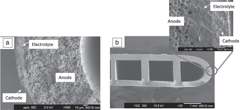
Inherent in the design of microtubular SOFCs is a gas channel of a few millimeters diameter or less. These cells are fabricated using 8 mol% Y2O3 or 10 mol% Sc2O3-stabilized zirconia (YSZ or ScSZ) or 10 mol% Gd-doped ceria (GDC) for the electrolyte, Ni-based cermet for the anode (NiO/YSZ or GDC = 60/40 weight), and a La0.6Sr0.4Co0.2Fe0.8O3 (LSCF)-GDC (LSCF/GDC = 70/30 weight) composite for the cathode. The typical preparation procedure is shown in Figure 1a. Numbers in the images in Figure 1b–c correspond to each process in Figure 1a. Tubes of the anode material (colored green) were prepared using extrusion technology. The extrudate was prepared by mixing anode materials (NiO and doped ceria or doped zirconia powders), pore former, binder, and water. The microtube and micro-flat tube, with a diameter or thickness of about 2 mm, were extruded from a metal mold using a piston cylinder-type extruder (1 in Figure 1b–c). An electrolyte layer was then coated onto each anode tube by dip-coating a slurry consisting of the electrolyte material (YSZ, ScSZ, or GDC) (2 in Figure 1b–c). After co-sintering the electrolyte and the anode tube at 1250–1400°C for 1–2 h (3 in Figure 1b–c), a cathode slurry mixture of LSCF and GDC powder was dip-coated onto the electrolyte and sintered at 1050°C (4 in Figure 1b–c). Note that the electrolyte and cathode layers do not cover the full length of the tube. Figure 2a–b shows scanning electron microscope (SEM) images of the microtubular and micro-flat tubular SOFCs, respectively, prepared by the method described previously. This technique allows for a variety of cell shapes, depending upon the stack design.
(a) Fabrication process of microtubular electrochemical cells and photographs of (b) microtubular and (c) micro-flat tubular cells at each stage in the process.Reference Suzuki, Funahashi, Yamaguchi, Fujishiro and Awano19,Reference Suzuki, Liang, Yamaguchi, Hamamoto and Fujishiro22 Numbers in the photos correspond to the process stages in (a). Note: SOFC, solid-oxide fuel cell.

Scanning electron microscope images of (a) a microtubular cell and (b) a micro-flat tubular cell.Reference Suzuki, Yamaguchi, Hamamoto, Sumi and Fujishiro21,Reference Suzuki, Liang, Yamaguchi, Hamamoto and Fujishiro22
One of the important factors for realizing high-performance electrochemical cells is to manage both densification of the electrolyte and retention of a porous and fine grain anode microstructure after the co-sintering process. The former can be realized at higher co-sintering temperatures (1400–1500°C), while the latter requires a lower co-sintering temperature. In order to achieve densification of the electrolyte without using high temperatures, the effect of shrinkage of the anode support during sintering on the densification of the electrolyte was studied.
Figure 3 shows the relationship between the initial porosity of the anode support and its shrinkage rate after high-temperature sintering at 1400°C with the resulting degree of electrolyte densification.Reference Yamaguchi, Shimizu, Suzuki, Fujishiro and Awano20 Note that the initial porosity of the anode support was controlled by varying the preheating temperature before coating the electrolyte layer. As can be seen in the SEM images, the densification of the electrolyte layer on the electrode support is strongly affected by the shrinkage of the support. A particular anode shrinkage (over ∼18%) is required in order to densify the electrolyte. Thus, controlling the shrinkage of the anode support (tube) is very important in obtaining a dense electrolyte layer, and low-temperature densification of the electrolyte can be realized by managing the shrinkage of the support by controlling the initial packing density of the ceramic powders. The authors have previously described a certain kind of binder that can effectively control the shrinkage of the anode support and realize dense electrolytes at the co-sintering temperature of 1250°C.Reference Suzuki, Yamaguchi, Hamamoto, Sumi and Fujishiro21
Anode shrinkage as a function of initial anode porosity, and the effect of shrinkage of the tubular anode support on densification of the electrolyte coating layer.Reference Yamaguchi, Shimizu, Suzuki, Fujishiro and Awano20
Performance of microtubular and micro-flat tubular cells
Typical SOFC performance of the microtubular electrochemical cells consisting of ScSZ electrolyte, Ni-ScSZ or Ni-YSZ anode, and LSCF-GDC cathode is shown in Figure 4.Reference Suzuki, Yamaguchi, Hamamoto, Sumi and Fujishiro21,Reference Suzuki, Liang, Yamaguchi, Hamamoto and Fujishiro22 The performance data presented are for single cells (3 cm length), for (a) a 2-mm diameter tubular cell (co-sintering temperature = 1250°C) with a cathode length of 1 cm (electrode area = 0.6 cm2) and (b) a 1.3-mm-wide and 2-mm-thick flat tubular cell (co-sintering temperature 1350°C) with a cathode length of 0.6 cm (electrode area = 1.6 cm2). Both were tested under similar fuel gas flow conditions (7.5 and 9.6 ml min–1 H2 flow per 1 cmReference Yamamoto2 electrode area, respectively). As can be seen in Figure 4a, the 2-mm-diameter cell (3 cm length) displayed ∼0.2–0.3 W of power for a single cell at 600°C and 650°C, respectively. The single cell output power can be increased by extending the tube length (and thus the electrode area); however, as current is collected from the tube ends, the current collection resistance is also increased, and the performance can be limited.Reference Suzuki, Yamaguchi, Fujishiro and Awano23 Using the micro-flat tubular design, on the other hand, it is possible to extend the electrode area without increasing the current collection resistance by widening the tube. This allows expansion of the cell electrode area without increasing the current collecting resistance compared to tubes of the same length. As shown in Figure 4b, the output power of a 13-mm-wide, 2-mm-thick anode supported micro-flat tubular SOFC reached 0.6 W and almost 0.8 W at 600°C and 650°C, respectively.Reference Suzuki, Liang, Yamaguchi, Hamamoto and Fujishiro22
Typical performance of single cells with 1-cm cathode length: (a) 2-mm diameter microtubular cell (cathode electrode area: 0.6 cm2, Ni-ScSZ/ScSZ/GDC/LSCF-GDC) and (b) 2-mm-thick, 1.33-mm-wide micro-flat tubular cell (cathode electrode area: 1.6 cm2, Ni-YSZ/ScSZ/GDC/LSCF-GDC) at a H2 flow rate of 7.5 and 9.6 ml min–1 per 1 cmReference Yamamoto2 electrode area, respectively.Reference Suzuki, Yamaguchi, Hamamoto, Sumi and Fujishiro21,Reference Suzuki, Liang, Yamaguchi, Hamamoto and Fujishiro22 Note: SOFC, solid-oxide fuel cell.
For further low-temperature operation of SOFCs, the use of a doped ceria electrolyte can be effective. Figure 5 shows the power output as a function of cell temperature for the 5-μm-thick GDC electrolyte microtubular cell (Ni-GDC/GDC/LSCF-GDC) in the temperature range of 297–542°C.Reference Suzuki, Yamaguchi, Fujishiro and Awano23 The two traces show the changes at maximum power (black circle symbol) and at a cell voltage of 0.7 V (red square symbol). The performance of the cell yielded 0.38 W cm–2 at 0.7 V and 542°C operating temperature, and then decreased as the operating temperature decreased. The observed power density was 3 mW cm–2 at 0.7 V and 294°C, with an open-circuit voltage (OCV) of 0.95 V.
Power output performance of the Gd-doped ceria (GDC) electrolyte cell (Ni-GDC/GDC/LSCF-GDC) as a function of cell temperature at maximum power operation (black) and at 0.7 V (red).Reference Suzuki, Liang, Yamaguchi, Hamamoto, Sumi, Fujishiro and Sammes24 Note: SOFC, solid-oxide fuel cell.
The microtubular cells can also be designed for the direct use of hydrocarbon fuel.Reference Suzuki, Liang, Yamaguchi, Hamamoto, Sumi, Fujishiro and Sammes24Figure 6 shows the performance of the cell (Ni-GDC/YSZ/GDC/LSCF-GDC) operated under a direct hydrocarbon fuel supply at temperatures as low as 610°C. Figure 6a shows the current-voltage (I-V) and current-power (I-P) characteristics for the microtubular SOFC at 610°C in hydrogen, methane (steam-carbon ratio, S/C = 0.079), and butane (S/C = 0.044). A maximum power density of 0.55 W cm–2 was obtained using hydrogen and about 0.5 W cm–2 in methane and butane at 610°C. As can be seen, the slopes of the I-V curves became steeper at lower current densities for hydrocarbon fuels because of carbon deposition on the anode at low S/C ratios, and the slopes were more gradual at higher current densities in the hydrocarbon fuels. This might be related to the promotion of electrochemical oxidation of deposited carbon and the reforming reaction of hydrocarbons at high current densities.
(a) Current-voltage (open markers) and current-power (filled markers) characteristics for the cell with the Ni-GDC anode at 610°C in H2, CH4, and C4H10. (b) Time courses of cell voltage at 0.2 A cm–2 for the cells with Ni-YSZ, Ni-ScSZ, and Ni-GDC anodes at 610°C in sequential flows of H2 (30 min), CH4 (30 min), and C4H10 (24 hours). The inset shows details of the first 100 min of operation.Reference Sumi, Yamaguchi, Hamamoto, Suzuki and Fujishiro25
Figure 6b shows the evolution with time of the cell voltage at a drawn current of 0.2 A cm–2 for the cells with Ni-YSZ, Ni-ScSZ, and Ni-GDC anodes at 610°C in successive flows of hydrogen, methane, and butane. For 30 min sequential flows of hydrogen and methane, the cell performance for each anode was almost the same. The cell voltage dropped to 0.7 V immediately after the fuel changed from methane to butane. Power generation ceased for the cells with Ni-YSZ and Ni-ScSZ anodes at 610°C after 3–4 h in butane. A large amount of deposited carbon was observed, and it caused the deterioration of the Ni catalytic activity and inhibition of fuel diffusion. On the other hand, the cell with the Ni-GDC anode continuously generated power for more than 24 h at 610°C in butane, although performance of the Ni-GDC anode was lower than that for the Ni-YSZ and Ni-ScSZ anodes before deterioration.
For further improvement of the cell performance at lower temperatures, a proton-conducting material was utilized for the microtubular cells.Reference Sumi, Yamaguchi, Hamamoto, Suzuki and Fujishiro25 Electrochemical performance of the anode-supported proton-conductive cell (Ba(Ce, Zr)O3 [BCZ] electrolyte and Ni-BCZ anode) is shown in Figure 7. As can be seen, the OCV of the cell was above 1.06 V in the temperature range from 450 to 550°C, which was higher than that of the ceria-based electrolyte.Reference Suzuki, Yamaguchi, Fujishiro and Awano23 The current density and power density at 0.75 V were 0.51, 0.25, and 0.13 A cm–2, and 0.38, 0.19, and 0.08 W cm–2 at 550, 500, and 450°C, respectively. From the impedance analysis at OCV, the ohmic resistance was found to be approximately 0.31, 0.42, and 0.53 Ω cm2 at 550, 500, and 450°C, respectively. As can be seen, by utilizing a proton conductor as the electrolyte, which has higher ionic conductivity, better fuel cell performance can be expected at lower operating temperatures.
Current-voltage (I-V) curves of the anode-supported proton-conductive cell (Ba(Ce, Zr)O3 [BCZ] electrolyte and Ni-BCZ anode).Reference Yamaguchi, Sumi, Hamamoto, Suzuki and Fujishiro26
Conclusions
A microtubular design has been shown to give quick start-up/shut-down operation ability to solid-oxide fuel cells (SOFCs).Reference Sammes, Du and Bove27–Reference Yashiro, Yamada, Kawada, Hong, Kaimai, Nigara and Mizusaki29 In addition to this advantage of microtubular cells, it has been shown that conventional anode-supported SOFCs with two types of microtubular cell structures could be fabricated using a simple extrusion and dip-coating technique and applied to low-temperature operation below 650°C. A Ni-GDC anode was found to be effective for direct hydrocarbon fuel usage around 600°C. An anode-supported tubular BCZ-based cell showed reasonable SOFC performance at lower operation temperatures (450–550°C). These results show that microtubular SOFCs are good candidates for small power sources. The practical operating temperature of a cell should be determined by the system requirements, as the type of application can limit module specification such as size and weight. It is therefore of importance to consider the end application to achieve further improvements.