


Impact Statement
Increasing strain on critical minerals poses a threat to the production of technologies including batteries, generators, and semiconductors. Many of these resources can be found as dissolved minerals in water like geothermal brines or wastewater. Thus, there is an urgent demand for processes that can recover these resources and supplement existing supply chains. However, the materials of interest are typically present only in dilute concentrations, necessitating removal of a substantial fraction of water before implementing selective downstream processes. The industry standard for brine processing involves solar evaporation: using ponds in hot, arid climates and waiting for months to years for enough of the water to naturally evaporate. Interfacial solar evaporation is a new technology that can accelerate this process by severalfold. By floating or suspending a porous material on the water that can convert sunlight to heat, the surface area for evaporation is enhanced and thermal energy can be concentrated at the air/water interface for faster and more efficient evaporation. However, there are still challenges with achieving sufficient evaporation rates at large scales to make this technology practical. In this study, we explore the integration of reflectors with different geometries to capture more sunlight to boost the evaporation rate. These reflectors could utilize space more efficiently in large-scale arrays where evaporators need to be appropriately spaced to avoid detrimental humidity build-up.
1. Introduction
The development of more advanced processes to extract and recover critical minerals has garnered increasing attention to bolster the supply chains of materials needed for technologies, including batteries, generators, and semiconductor devices [Reference Deberdt, Smith, Calderon and McCall1, Reference Greim, Solomon and Breyer2, Reference Reich and Simon3, Reference Sun, Liu, Zhao and Hao4]. Many of these critical minerals, such as cobalt, are geographically isolated and may be dependent on unsustainable mining operations or unethical labor practices [Reference Calvão, Mcdonald and Bolay5, Reference Savinova, Evans and Lèbre6]. Thus, there is a demand to develop more efficient separation processes that promote a more secure resource economy. Water plays an important role in this effort because a variety of critical minerals can be found across different concentration ranges in streams, including natural and wastewater sources [Reference Kazi, Chen and Eatman7, Reference Can Sener, Thomas and Hogan8, Reference Subasinghe, Zhang, Shi, Rezaee and Taleghani9, Reference Loganathan, Naidu and Vigneswaran10].
Solar evaporation presents a low-cost method to separate water from salts and other dissolved species for water treatment and resource recovery applications. This strategy is currently employed for the extraction of minerals such as lithium and nitrates from brines [Reference Darling11]. However, the current deployment of evaporation ponds is inefficient and raises environmental concerns as they occupy large areas of land, and their rates of evaporation are typically slow due to the transparency of water to most wavelengths of solar irradiation [Reference Liu and Agusdinata12, Reference Roche, Link, Marinova, Coroama and Finkbeiner13]. In the Salar de Atacama, brine evaporation typically takes more than 1 year to achieve suitable lithium concentrations for downstream extraction and purification [Reference Torres, Pérez and Galleguillos Madrid14]. Interfacial solar evaporation has emerged as a promising method of accelerating water evaporation rates by severalfold [Reference Cui, Dong and Cao15, Reference Yang, Yang and Chen16, Reference Wu, Chen and Wang17]. By submerging or suspending a porous, photothermal material on water, water can be wicked via capillary action to the surface where sunlight is converted to heat. The localization of heat at the air–water interface boosts the energy efficiency and evaporation rate per unit of projected area. Numerous combinations of porous photothermal materials and coatings have been demonstrated to be effective for interfacial solar evaporation [Reference Cao, Thomas and Li18, Reference Wang, Tian and Huan19, Reference Yang, Lu and Li20]. More importantly, the geometry of the materials has proven to be important in governing the evaporation rate and resistance to salt scaling [Reference Liang, Wang and Yu21, Reference Xu, Li and Finnerty22]. Three-dimensional (3D) suspended geometries such as rods, cones, and arches have demonstrated the highest evaporation rates due to the increased surface area for evaporation and additional environmental energy harvesting due to evaporative cooling effects [Reference Bu, Zhou and Lei23, Reference Kazi, Avram and Wang24, Reference Wu, Dong and Cai25, Reference Wu, Quan and Huang26].
An important aspect of the practical implementation of 3D evaporators that has been less explored is the changes in their performance when they are scaled up from individual devices into large arrays. In particular, the kinetics and transport of vapor between devices will depend on factors such as the environmental conditions, the individual evaporator heights, and the array spacing [Reference Zhang, Mittapally, Oluwade and Chen27]. An intrinsic trade-off exists between the number of evaporators in an array and the array spacing; space between neighboring evaporators is needed to minimize local humidity buildup that limits evaporation, while also trying to fit enough evaporators to achieve a high rate of evaporation. Finnerty et al. showed that stalk-like geometries provide an effective ratio of total surface area for evaporation to the projected area occupied in the plane of the water level, which makes them promising for efficient space utilization in large-scale arrays [Reference Finnerty, Menon and Conway28]. Typically, in lab-scale demonstrations, such evaporators are fitted into floating, nonabsorbing support materials such as polystyrene foam. Thus, a large-scale floating array will inevitably have space in between evaporators that does not actively contribute to energy conversion for evaporation but needs to be maintained for effective vapor escape.
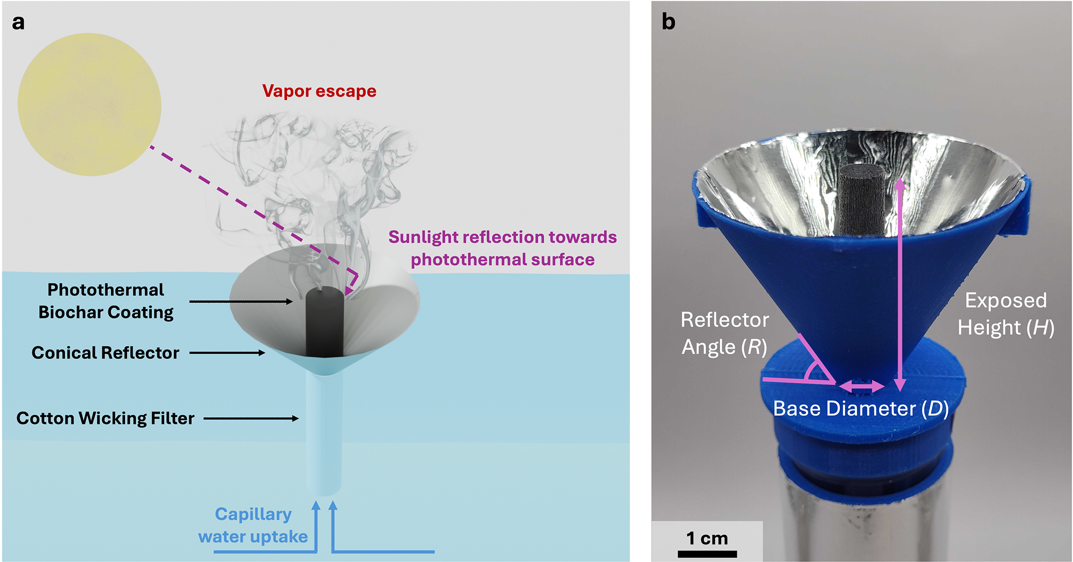
One possible strategy to capture and convert more solar energy to drive water evaporation is the integration of a light reflector with a 3D interfacial solar evaporator. Different reflector configurations have been studied for related applications in solar stills, where a reflector can concentrate and redirect sunlight toward an absorber to boost distillation rates. The position of the reflector either inside or outside of the still, as well as the shape and material of the absorber, can have different effects on the distribution of thermal energy, condensation of the distillate, and the achievable evaporation rate [Reference Maghsoudian, Rashidi and Rafee29, Reference Omara, Kabeel and Abdullah30]. Several porous and photothermal absorbers have been studied, including sponges, clays, and carbon foams [Reference Shoeibi, Saemian and Kargarsharifabad31]. The integration of a passive reflector for a 3D interfacial solar evaporation system has recently been demonstrated by Hu et al., where they used a truncated cone reflector with their 3D polymer covalent organic framework material to increase the absolute evaporation rate by more than threefold [Reference Hu, Zhao and Hu32]. However, beyond this initial demonstration, the field is lacking systematic study to understand the geometric optimization and practical viability of passive reflectors for 3D interfacial solar evaporators. Solar concentration has also commonly been employed for solar thermal technologies to collect sunlight over a large area and to focus it with a greater intensity onto a smaller absorber, including through concentration systems such as Fresnel lenses, parabolic concentrators, and parabolic troughs [Reference Iqbal, Ullah and Shin33]. While some literature reports demonstrate interfacial solar evaporators operating under irradiances exceeding 1-sun, typically by adjusting the power or working distance of a solar simulator, these conditions are unrealistic for practical applications [Reference Lei, Liu and Hu34, Reference Wang, Zhan and Li35]. In this study, we assessed the performance of 3D rod-shaped evaporators with conical reflectors of different heights and angles to understand the influence of the reflector geometry on the achievable evaporation rate (Figure 1a, b). A conical geometry was selected both due to its simplicity for fabrication and its ability to reflect light broadly across the photothermal surface rather than at a small hot spot. We observed that wider conical reflectors typically resulted in faster water evaporation, but a lower evaporation rate per unit area due to the lateral space occupied by the reflector.
(a) Schematic illustrating a conical reflector centered around a rod-shaped photothermal evaporator. The reflector redirects sunlight toward the photothermal surface for enhanced photothermal conversion and evaporation. (b) Photograph of the suspended OPB@HWF evaporator loaded onto a 3D-printed support with a conical reflector. The geometric parameters of the reflector are labeled, including the exposed height (H), reflector angle (R), and base diameter (D).

Figure 1. Long description
Panel a is a schematic diagram. At the bottom, blue arrows labeled Capillary water uptake point upward into a Cotton Wicking Filter submerged in water. Above the water line, the filter is encased in a Conical Reflector. At the center of the reflector is a rod with a Photothermal Biochar Coating. A yellow sun in the top-left corner sends a dashed purple line representing sunlight, which reflects off the cone's interior toward the rod. Wisps of gray smoke labeled Vapor escape rise from the top of the rod.
Panel b is a photo of the physical device. A black rod is centered inside a silver-lined blue 3 D-printed cone. Pink double-headed arrows and arcs define geometric parameters. A horizontal arrow at the narrow bottom of the cone is labeled Base Diameter D. A vertical arrow from the base to the top of the rod is labeled Exposed Height H. An arc between the horizontal base and the sloped side of the cone is labeled Reflector Angle R. A 1 cm scale bar is located at the bottom-left.
2. Methods
2.1. Preparation of Reflector-Integrated Evaporator
Olive-pit biochar (OPB) was crushed into a fine powder using a shaker ball mill. The OPB was mixed into a container with alumina balls in a 1:15 biochar-to-ball mass ratio and was placed on a shaker mill for 24 h. The crushed OPB powder was retrieved using a mesh sieve with an opening size of 0.86 mm. The photothermal OPB coating solution was prepared by stirring 40 mg mL−1 of OPB powder and 40 mg mL−1 of ethyl cellulose in ethanol overnight. Cylindrical cotton humidifier wicking filters (HWFs) with diameters of approximately 8 mm were obtained commercially and cut to lengths of 12 cm. The length of the segment of the top of the HWF that would be exposed to the air during evaporation was measured, and the area below it was masked using painter’s tape. The OPB coating was brush-coated onto the HWF and allowed to dry at room temperature for 1 h in a fume hood before removing the tape, forming the OPB@HWF evaporator. The OPB@HWF evaporator was soaked in deionized water for 24 h prior to experiments to ensure full saturation. The OPB@HWF evaporator was subsequently loaded onto a custom support with a 9 mm opening which was made via 3D-printing (Digilab 3D45, Dremel) using polylactic acid filament (PLA) (Supplementary Figure S1).
Conical reflectors were designed using computer-aided design (CAD) with varying combinations of reflector angles and heights (Supplementary Figure S2). The design was split into two halves that were 3D-printed separately using PLA to make it easier to line the reflector with aluminum foil with minimal wrinkling. Fins were printed on the outside of the conical support to more easily join the two halves together. The inside of each half of the conical support was lined with a reflective aluminum foil using double-sided tape. The aluminum foil was applied carefully to minimize creases. The two halves of the reflector were joined by taping together the external fins. The base of the reflector was then placed on top of the evaporator support loaded with an OPB@HWF evaporator (Figure 1b).
2.2. Material Characterization
The fiber morphology and porosity of the HWF and OPB@HWF samples were characterized by scanning electron microscopy (SEM) (Hitachi S-4700). The optical absorption of the samples across the solar irradiation spectrum was measured from 300 to 2500 nm using a double-beam ultraviolet-visible-near-infrared (UV-vis-NIR) spectrophotometer (CARY 5000, Agilent) using a PbSmart NIR detector equipped with a 150 mm integrating sphere. The droplet absorption rates of the samples were measured using a drop shape analyzer (DSA25, KRÜSS).
2.3. Solar Evaporation Experiments
A class AAA solar simulator (SciSun-AM1.5G, Sciencetech) was used to illuminate the test area, including evaporators and reflectors for solar evaporation rate measurements. The irradiance of the solar simulator was calibrated to 1000 W m−2 (1-sun) at the height of the top surface of the evaporator system and was measured using a thermal power sensor (S405C, Thorlabs). The light was constantly incident on the photothermal surface at the normal angle for the full duration of all experiments. The evaporation rate was measured by monitoring the change in mass of water using a precision balance (Scout STX223, OHAUS) and recording the data to a computer via a USB connection. The measured evaporation rate was normalized to the projected area of the entire evaporator, including the reflector, when one was used. The evaporator surface temperature profile was imaged using a thermal camera (T530, Teledyne FLIR). Evaporation experiments were performed in a box to minimize the influence of spurious changes in air flow or temperature from the surroundings. Due to the low air circulation in the testing environment, the measured evaporation rates provide a conservative bound relative to realistic conditions with more air flow. The ambient conditions were monitored using a digital temperature and humidity data logger (GSP-6, Elitech). All experiments were performed across an average relative humidity of 53.6% ± 9.2% and an average air temperature of 22.3 ± 1.0°C.
3. Results and Discussion
3.1. Characterization of Evaporator Materials
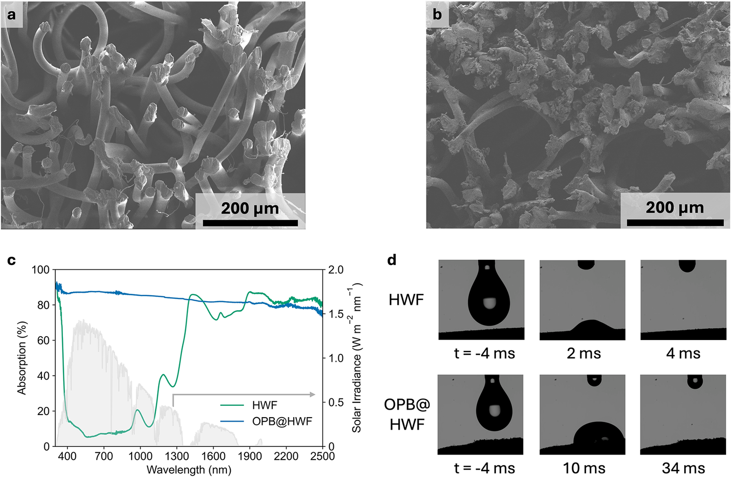
Previously, our group reported on the performance of delignified wood rods with different geometries for interfacial solar evaporation and observed that for taller rods, the evaporation rate decreased over time and was limited by the rate of vertical capillary uptake [Reference Kazi, Avram and Wang24]. In this study, we mitigated this effect by instead using HWFs as the rod-shaped substrate material, which demonstrate improved rates of water uptake. HWF materials have been reported in the literature as being effective for interfacial solar evaporation due to their porous structure and high hydrophilicity [Reference Finnerty, Menon and Conway28]. The HWF rods exhibit a highly porous structure consisting of embedded cellulose fibers ranging from 10 to 40 μm in diameter, as shown by SEM (Figure 2a). The HWF rods were brush-coated with a photothermal OPB coating to harness solar energy for enhanced interfacial water evaporation (OPB@HWF). Following brush-coating, the porous structure of the original HWF is preserved with deposits of the photothermal OPB coating observable across the surface of the fibers (Figure 2b).
SEM images of the top surface of (a) bare HWF and (b) OPB@HWF. (c) UV-vis-NIR absorption spectra of bare HWF and OPB@HWF displayed across the solar irradiance spectrum. The shaded region represents the irradiance of the AM1.5G solar spectrum. (d) Images of water droplet absorption over time for bare HWF and OPB@HWF surfaces, where t = 0 ms is set as the frame of the video recording when the droplet first contacted the surface.

Figure 2. Long description
The figure is divided into four panels labeled a through d.
* Panel a: An S E M micrograph of bare H W F showing a network of smooth, curved, cylindrical fibers. A scale bar at the bottom right indicates 200 micrometers.
* Panel b: An S E M micrograph of O P B at H W F showing the same fiber network but now heavily coated with irregular, flaky, and granular particles. A scale bar at the bottom right indicates 200 micrometers.
* Panel c: A line graph plotting Absorption in percent on the left y-axis and Solar Irradiance in W m super -2 nm super -1 on the right y-axis against Wavelength in nm on the x-axis from 400 to 2500. A light gray shaded area represents the A M 1.5 G solar spectrum. The bare H W F curve (green) shows low absorption between 400 and 1300 nm with several peaks and troughs. The O P B at H W F curve (blue) shows a consistently high absorption near 80 percent across the entire measured spectrum.
* Panel d: Two rows of time-lapse photos showing water droplet contact.
- Top row (H W F): At t = -4 ms, a droplet hangs above the surface. At 2 ms, the droplet has spread significantly. At 4 ms, the droplet is completely absorbed.
- Bottom row (O P B at H W F): At t = -4 ms, a droplet hangs above the surface. At 10 ms, the droplet remains as a hemisphere on the surface. At 34 ms, the droplet is still visible and only partially absorbed, indicating slower wetting compared to bare H W F.
The OPB coating exhibits a high degree of water-stability and adhesion to the HWF substrate, showing no signs of fading in coloration or shedding of biochar particles after soaking in water for 14 days (Supplementary Figure S3) or after 1 hour of agitation via ultrasonication (Supplementary Figure S4). The OPB@HWF evaporator exhibited >80% absorption of light across most of the solar irradiance spectrum, making it a suitable candidate for effective photothermal conversion (Figure 2c). The hydrophilicity of the HWF substrate material was characterized through a droplet absorption test (Figure 2d). The droplet was absorbed significantly faster by the bare HWF surface than the OPB@HWF surface. Thus, the OPB coating was only applied to the region of the HWF surface that would be exposed to the air for evaporation, leaving the more hydrophilic bare HWF submerged in the water for higher rates of water absorption and uptake.
3.2. Assessment of Evaporation Performance
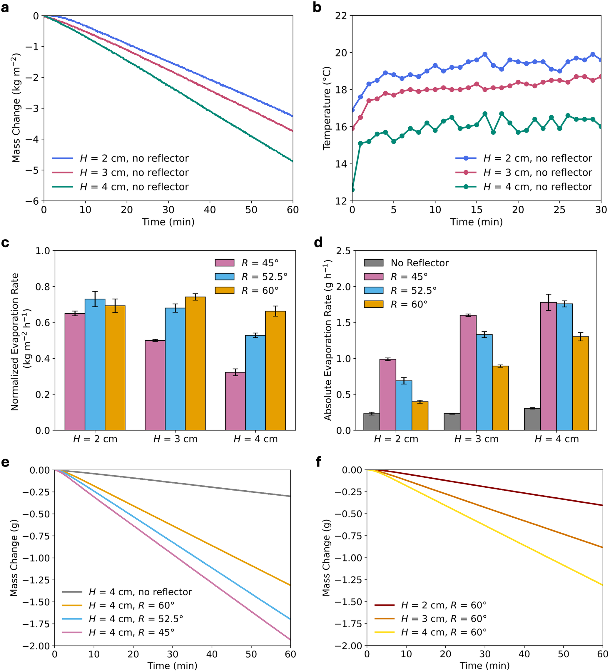
To test the evaporation performance of the OPB@HWF evaporators, they were loaded onto the custom 3D-printed support that kept them suspended at a fixed height in a container of water. The rod rests on a thin, annular base that ensures most of the bottom face of the HWF rod remains exposed to the water. First, we evaluated the evaporation performance of the OPB@HWF evaporators with different exposed heights without the integration of a reflector (Figure 3a). The trend showed that taller evaporators typically yielded higher evaporation rates, with the shortest evaporators demonstrating an evaporation rate of 3.75 ± 0.30 kg m−2 h−1 and the tallest evaporators exhibiting an evaporation rate of 4.87 ± 0.30 kg m−2 h−1. This trend can be attributed to increased evaporation surface area and to evaporative cooling effects, wherein taller evaporators reach lower surface temperatures as more thermal energy from the surface is converted into the latent energy required for water to evaporate. Consequently, the increased temperature differential with the warmer ambient air results in additional energy being harnessed from the environment and utilized to continuously boost the rate of evaporation. This phenomenon was observed and confirmed through infrared thermography across the different exposed heights, with the OPB@HWF evaporator with an exposed height of 4 cm remaining over 3 °C cooler than that with an exposed height of 2 cm after 30 minutes of evaporation under 1-sun illumination (Figure 3b and Supplementary Figure S5). This trend is consistent with observations from our prior work and from other studies that have shown that even small temperature differentials can boost evaporation rates through evaporative cooling, the effect of which can be further pronounced in tall, 3D evaporator structures with increased surface areas [Reference Kazi, Avram and Wang24, Reference Caratenuto and Zheng36]. We also observed that the OPB@HWF rod could maintain a stable rate of evaporation over the course of several days, confirming that the rate of capillary uptake was high enough to sustain continuous interfacial evaporation (Supplementary Figure S6). We determined that experiments lasting 1 hour were sufficient to compare the evaporation performance of OPB@HWF evaporators integrated with conical reflectors after observing that under longer duration experiments, the evaporation rate is typically stable and is only affected when the container runs out of water (Supplementary Figure S7). In comparison, a conical reflector with a material that has less-efficient vertical capillary uptake, such as our previously studied delignified wood evaporator (OPB@DW), showed rapid attenuation of the evaporation rate over the course of several hours. These observations confirm HWF as a reliable substrate candidate for this study to ensure that insufficient capillary water uptake does not overshadow changes in evaporation performance caused by different reflector geometries.
(a) Mass change per unit area of OPB@HWF evaporators of different exposed heights and no conical reflector. (b) Surface temperature of OPB@HWF evaporators with different exposed heights and no conical reflector. (c) Average hourly evaporation rate normalized to the projected area of OPB@HWF evaporators with different combinations of exposed heights and reflector angles. (d) Average hourly absolute evaporation rate (not normalized to the projected area) of OPB@HWF evaporators with different combinations of exposed heights and reflector angles. (e) Mass change of OPB@HWF evaporators with an exposed height of 4 cm and varying reflector angles or no conical reflector for comparison. (f) Mass change of OPB@HWF evaporators with a reflector angle of 60° and varying exposed heights.

Figure 3. Long description
Panel a is a line graph showing mass change in kilograms per meter-squared over 60 minutes. Three linear downward trends represent exposed heights H equals 2, 3, and 4 centimeters without reflectors. The H equals 4 centimeter line shows the steepest negative slope, reaching approximately minus 4.8 kilograms per meter-squared.
Panel b is a line graph of surface temperature in degrees Celsius over 30 minutes. Temperatures stabilize after 5 minutes. The H equals 2 centimeter series is highest at approximately 19 degrees Celsius, while H equals 4 centimeters is lowest at approximately 16 degrees Celsius.
Panel c is a grouped bar chart of normalized evaporation rate in kilograms per meter-squared per hour. It compares reflector angles R equals 45, 52.5, and 60 degrees across heights H equals 2, 3, and 4 centimeters. For H equals 4 centimeters, the 60-degree angle significantly outperforms the 45-degree angle.
Panel d is a grouped bar chart of absolute evaporation rate in grams per hour. It includes a no-reflector control which is consistently the lowest. For all heights, the 45-degree reflector angle produces the highest absolute evaporation rate.
Panel e is a line graph of mass change in grams over 60 minutes for H equals 4 centimeters. It compares no reflector with three angles. The 45-degree angle shows the most rapid mass loss, reaching nearly minus 2.0 grams.
Panel f is a line graph of mass change in grams over 60 minutes for a fixed 60-degree reflector angle. It shows that increasing height H from 2 to 4 centimeters increases the rate of mass loss.
To understand the influence of conical reflector geometry on the rate of evaporation, combinations of three different exposed heights (H = 2, 3, and 4 cm) and reflector angles (R = 45°, 52.5°, and 60°) were tested in deionized water under 1-sun illumination for 1 hour (Figure 3c and Supplementary Figure S8). Each of these combinations of parameters was tested in triplicate to account for possible variations across samples. Evaporators with exposed heights taller than 4 cm and with reflector angles narrower than 45° were not tested due to physical constraints imposed by the integration of an appropriately large conical reflector inside of our experimental apparatus. Reflector angles wider than 60° were not tested as the increasingly restricted space between the evaporating surface and the reflector could hinder effective vapor transport away from the evaporator. The evaporation rate normalized per unit of projected area for all geometries decreased dramatically compared to the OPB@HWF evaporator without a conical reflector, with the highest evaporation rate only reaching 0.74 kg m−2 h−1 for the reflector and evaporator with an angle of 60° and an exposed height of 3 cm. However, the absolute evaporation rate (not normalized to the projected area) increased by severalfold in comparison to the scenario in which no reflector was integrated (Figure 3d, e). This effect can be attributed to the large lateral area that the reflector occupies in comparison to the smaller projected area of the HWF rod by itself. For reflector angles that create a wider conical reflector, the absolute rate of evaporation was the highest due to increased light capture for photothermal conversion, but the normalized rate of evaporation per unit area was the lowest due to the larger projected area of the reflector (Figure 3d and Supplementary Figure S8). A similar trend was observed for changes in the exposed height, where taller evaporators yielded a higher absolute rate of evaporation but a lower normalized rate of evaporation per unit area due to the larger area occupied by a taller conical reflector (Figure 3f).
These discrepancies point to the importance of carefully defining figures of merit in interfacial solar evaporation studies, particularly when comparing different device designs. Taller and thinner evaporators will naturally yield higher normalized evaporation rates, but those rates cannot be linearly scaled up for practical applications. For example, Chen et al. reported on a cellulose fiber evaporator that demonstrated an individual evaporation rate of 382 kg m−2 h−1 due to its small projected area, but an array of 100 evaporators in the same ambient conditions achieved an overall evaporation rate of only 3.4 kg m−2 h−1 [Reference Chen, Yang and Zheng37]. A plethora of 3D interfacial solar evaporator materials and designs have been reported in the literature, with many commonly achieving normalized evaporation rates between 2 and 5 kg m−2 h−1 [Reference Wu, Dong and Cai25, Reference Hou, Li and Qi38, Reference Li, He and Jiang39]. The OPB@HWF evaporators in this study achieved normalized evaporation rates at the high end of this range without conical reflectors, demonstrating that their evaporation performance is on par with many state-of-the-art designs. Thus, considering that the integration of conical reflectors increased the absolute rate of evaporation by over sixfold in some of the geometries, it is worthwhile to further investigate their viability for larger-scale and practical applications.
In saline solutions, the presence of a reflector can exacerbate the effect of salt scaling. We observed that the evaporation rates steadily decreased over the course of 24 hours across varying reflector angles with visible formation of salt crystals across the OPB@HWF surface (Supplementary Figures S9–S10). The evaporator could recover some of its evaporation performance following rinsing with deionized water, but after the first cycle, the evaporation rate was prone to decrease faster due to salt scaling (Supplementary Figure S11). While the OPB@HWF evaporator was selected as a model system for this study and has not been optimized to mitigate salt scaling, it is anticipated that reflectors will exacerbate the challenge in interfacial solar evaporation systems. The increased photothermal conversion from the reflector would increase the flux of water vapor out of the evaporator, but if the rate of capillary uptake into the porous matrix cannot match the increase, it will result in an imbalanced mass flow that would consequently intensify the rate of dry-out and salt accumulation on the evaporator surface.
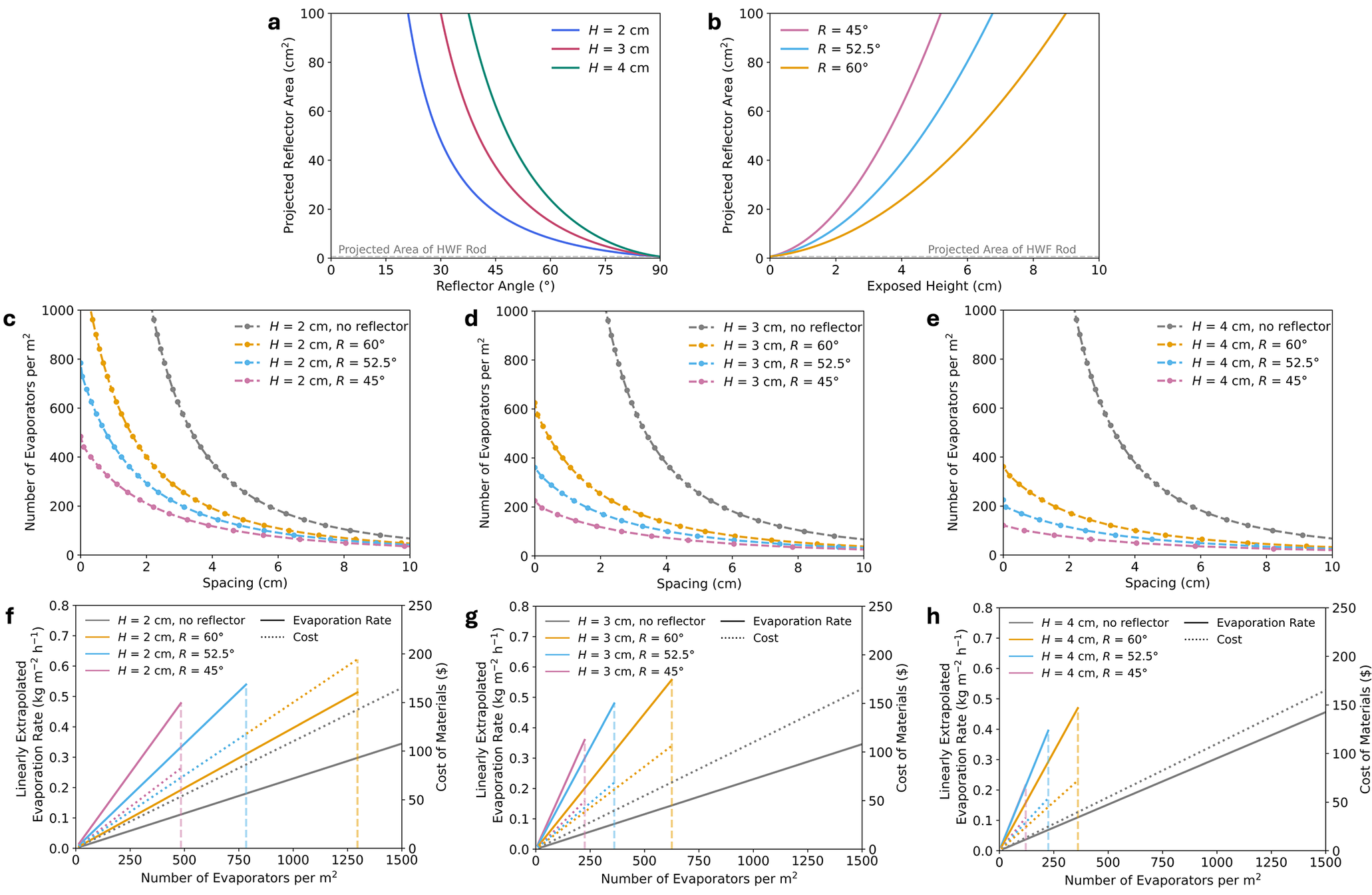
Based on these findings, it can be understood that a tradeoff exists between the projected area of a conical reflector and the achievable evaporation rate for practical applications. A geometric analysis of the influence of each of the parameters that determine the overall projected area shows that designing reflectors with wider angles or taller heights can dramatically increase the projected area (Figure 4a, b). The influence of the base diameter of the reflector on the overall projected area was significantly less considerable across different combinations of angles and exposed heights (Supplementary Figure S12). We did not measure the evaporation rates of OPB@HWF evaporators with varying reflector base diameters as it would have required acquiring different-sized HWFs from different commercial sources, which could have introduced variations in the different materials based on their processing. However, the base diameter should also be optimized when considering that changes to the diameter of the evaporator material consequently affect the surface area available for interfacial solar evaporation.
(a) Projected reflector area as a function of reflector angle for different fixed exposed heights and a base diameter of 9 mm. (b) Projected reflector area as a function of exposed height for different fixed reflector angles and a base diameter of 9 mm. (c–e) Number of evaporators that can be fit in an array with an area of 1 m2 for evaporators with exposed heights of (c) H = 2 cm, (d) H = 3 cm, and (e) H = 4 cm. The points represent discrete numbers of evaporators that can be fit with even spacings in both directions of the lateral plane. (f–h) Ideal linearly extrapolated evaporation rates and costs of materials for different numbers of evaporators fit into an array with an area of 1 m2 with exposed heights of (f) H = 2 cm, (g) H = 3 cm, and (h) H = 4 cm. The solid lines correspond to the evaporation rate (left axis) and the dotted lines correspond to cost (right axis). The vertical dashed lines indicate the maximum number of a particular evaporator that can be fit into a 1 m2 array based on geometric constraints.

Figure 4. Long description
A multi-panel figure with eight line graphs labeled a through h.
Panel a: Projected Reflector Area in centimeters-squared versus Reflector Angle in degrees. Three curves for heights H equals 2, 3, and 4 centimeters show a non-linear decay as the angle increases from 0 to 90 degrees. Higher H values result in higher projected areas.
Panel b: Projected Reflector Area versus Exposed Height in centimeters. Three curves for angles R equals 45, 52.5, and 60 degrees show a quadratic increase as height increases from 0 to 10 centimeters. Smaller angles result in higher projected areas.
Panels c, d, and e: Number of Evaporators per meter-squared versus Spacing in centimeters for heights 2, 3, and 4 centimeters respectively. Each panel shows four decaying curves representing no reflector and reflector angles of 60, 52.5, and 45 degrees. The no-reflector curve is the highest, while the 45-degree curve is the lowest, indicating that reflectors and smaller angles limit the maximum density of evaporators.
Panels f, g, and h: Linearly Extrapolated Evaporation Rate in kilograms per meter-squared per hour on the left Y-axis and Cost of Materials in dollars on the right Y-axis versus Number of Evaporators per meter-squared. Solid lines for evaporation rate and dotted lines for cost show linear increases. Vertical dashed lines mark the geometric limit for each configuration. As height increases from f to h, the maximum number of evaporators decreases, and the slope of the evaporation rate increases for the reflector configurations compared to the no-reflector baseline.
The geometry of conical reflectors must also be considered for their integration into large-scale arrays for practical applications for water treatment and resource concentration. Different numbers of reflector-integrated evaporators can be fit into a unit of area depending on the spacing between evaporators and the projected area occupied by a reflector based on its geometric parameters (Figure 4c–e). The spacing between the evaporators has important consequences on the achievable evaporation rate, as sufficient spacing between neighboring evaporators is necessary to allow water vapor to escape efficiently. If evaporators are positioned too close together, one can anticipate that the overall rate of evaporation would decrease according to the Clausius–Clapeyron relation if the local water vapor pressure increases due to insufficient vapor diffusion or convection. Additionally, insufficient spacing could cause evaporated water to recondense on the evaporator surfaces, which would result in thermal losses, further lowering the evaporation efficiency. Thus, despite the fact that many more OPB@HWF evaporators could be fit into a given area without reflectors than with the integration of reflectors, they may not yield a higher overall rate of evaporation as an array. This consideration highlights the need for more nuanced analyses of evaporation performance in the literature where thin evaporators with small projected areas are often reported with exceptionally high evaporation rates per unit area but likely cannot scale to achieve that same evaporation rate in any practical setting.
We extended this analysis by estimating the most ideal evaporation rate achievable by 1 m2 arrays of different numbers of evaporators through a simple linear extrapolation (Figure 4f–h). Through this, we can compare the number of different types of evaporators that would be needed to meet a particular water evaporation benchmark. Due to the aforementioned effects of the array spacing on water vapor transport and evaporation performance over time, we expect that the real achievable evaporation rates for large systems should fall beneath the ideal linear estimates. This deviation would be in alignment with the calculations performed by Zhang et al. demonstrating decaying evaporation rates across the rows of a large-scale array of rod-shaped evaporators due to the localized buildup of humidity in the system [Reference Zhang, Mittapally, Oluwade and Chen27]. The integration of a reflector could dramatically decrease the number of evaporators needed to achieve a particular evaporation rate compared with using OPB@HWF evaporators without a reflector and would make effective use of the space between evaporators to boost evaporation performance while still allowing water vapor to be transported away from the evaporation interface. We performed a simple technoeconomic analysis (TEA) to consider the cost of materials for each evaporator configuration for comparison alongside the water evaporation rates (Supplementary Note S1 and Supplementary Tables S1–S3). Although integrating reflectors increases the cost of fabricating an individual evaporator, it still decreases the total cost of materials needed to achieve the range of evaporation rates accessible using conical reflectors compared to using many more OPB@HWF evaporators without reflectors. Further study is needed to elucidate the practically achievable evaporation rates at large scales without conical reflectors and their dependence on array spacings and environmental conditions. In combination with TEA, this would help to determine whether conical reflectors would be cost-effective enough to integrate in relation to the achievable evaporation rate for different array scenarios.
4. Conclusions
We demonstrated the integration of a conical reflector with a 3D cylindrical cotton-based evaporator, yielding lower evaporation rates when normalized to the large projected area of the reflector but achieving a multifold increase in the evaporation of water through enhanced light capture and utilization. We observed that both the reflector angle and the exposed height of the evaporator system influenced the achievable evaporation rate. While wider angles and taller exposed heights resulted in increased evaporation due to enhanced light capture and increased surface area for interfacial evaporation and evaporative cooling, respectively, they also yielded larger projected areas. Based on their evaporation rates, reflectors demonstrate poor performance on the basis of an individual evaporator but could have utility in large-scale arrays where spacing between neighboring evaporators is critical to avoid limiting the transport of water vapor away from the evaporation interfaces. Reflectors could present an opportunity to efficiently utilize the space between neighboring evaporators to boost evaporation without blocking vapor escape.
The performance of reflector geometries aside from conical reflectors can also be explored, such as hyperbolic and elliptical reflectors, which can offer different ranges of angles of solar concentration. There is a large phase space of other important parameters to explore in these systems, including changes in mass and heat transport in the presence of forced air convection, different wicking materials, and different 3D evaporator geometries. Further study, including both multiphysics modeling and experiments, is needed to more quantitatively understand how the reflector geometry influences the intercoupled heat and mass transport processes in specific 3D interfacial solar evaporator systems, such as the transport of vapor away from the porous surface and the loss of heat to the ambient environment. Further study is also required to elucidate the effect of the spacing between neighboring evaporators in large-scale arrays on vapor transport kinetics and evaporation rates, which could consequently inform on the practical viability of reflector-integrated evaporators. For practical applications, TEA should be considered, especially over longer periods of operation, relative to the number of evaporators that need to be fabricated and their corresponding water evaporation rates. One major limitation of integrating reflectors into interfacial solar evaporators is the exacerbation of salt scaling in saline solutions. Additional work is needed to balance the light concentration of the reflector with mitigating the effects of salt crystallization for realistic applications such as brine concentration or desalination. This will require a simultaneous tuning of both the reflector geometry and the evaporator material for optimized mass transport rates.
Open peer review
To view the open peer review materials for this article, please visit http://doi.org/10.1017/S2978171X26000007.
Supplementary material
To view supplementary material for this article, please visit http://doi.org/10.1017/S2978171X26000007.
Data Availability Statement
The data that support the findings of this study are available from the corresponding author, S.D., upon reasonable request.
Author Contributions
O.A.K. and A.C.A. contributed equally to this work. O.A.K. and S.D. conceived the project. O.A.K. and A.C.A. designed and conducted the experiments, processed the data, interpreted the results, and drafted the manuscript. P.Z. and J.B.D. performed technoeconomic analyses and related calculations. X.Z. performed SEM characterization. B.S. and J.W.E. performed UV-Vis-NIR absorption measurements. All authors contributed to proofreading and revising the manuscript.
Acknowledgments
The authors thank Matthew Mallory and Christopher Carstens of Carbo Culture for supplying the OPB and providing valuable insights. The authors thank Beihai Ma, Dileep Singh, and Ozge Kahvecioglu of Argonne National Laboratory for assistance with ball milling.
Financial Support
This work was supported by the U.S. Department of Energy, Office of Energy Efficiency and Renewable Energy (grant DE-EE0009505); O.A.K. was supported by the National Science Foundation Graduate Research Fellowship Program (grant No. 214000) and the Science Olympiad USA Foundation (Science Olympiad Alumni Research Grant). Any opinions, findings, and conclusions or recommendations expressed in this material are those of the authors and do not necessarily reflect the views of the National Science Foundation.
Competing Interests
Author Seth Darling is the Editor-in-Chief of Cambridge Materials: Water. Seth Darling was not involved in the editorial handling of this manuscript, or in the decision to publish. The peer review process was managed independently by the Associate Editor Hao-Cheng Yang.


 Open access


Comments
Editorial Office
Cambridge Materials: Water
Cambridge University Press
Cambridge, United Kingdom
Dear Editors,
We are pleased to submit our manuscript, “Assessment of Conical Reflectors for Enhanced Interfacial Solar Evaporation,” for consideration in Cambridge Materials: Water. This work was carried out by researchers at Argonne National Laboratory, the University of Chicago, and Northwestern University, and we believe it is well suited to the journal’s mission of advancing materials science for water treatment, resource efficiency, and sustainability.
Interfacial solar evaporation has emerged as a compelling low-cost approach to accelerate water evaporation for applications including desalination, potable water production, and the concentration of dissolved critical minerals such as lithium, cobalt, and nitrates from geothermal brines and wastewater streams. Despite rapid progress in photothermal material development, translating laboratory-scale evaporator designs into practical large-scale systems remains a significant challenge. Our study addresses this gap by providing the first systematic assessment of conical reflectors integrated with three-dimensional cylindrical photothermal evaporators to boost light capture and water evaporation rates.
The key contributions of this work are as follows. First, we demonstrate that conical reflectors produce a multifold increase in the absolute quantity of water evaporated by redirecting incident sunlight onto the photothermal surface, while simultaneously revealing that the evaporation rate normalized to the reflector’s projected area is substantially reduced. This apparent paradox underscores a critical and underappreciated issue in the field: the evaporation rate per unit projected area (a widely used figure-of-merit) may be misleading when evaluating designs intended for large-scale deployment. Second, we show that both the reflector angle and the exposed evaporator height govern the achievable performance, with wider angles and taller structures yielding higher absolute evaporation rates through enhanced light capture and evaporative cooling effects, at the cost of a larger lateral footprint. Third, we extend these findings to a technoeconomic analysis of large-scale arrays, demonstrating that reflector-integrated evaporators can reduce the total number of devices needed to achieve target evaporation rates and can make productive use of the inter-evaporator spacing that is otherwise required for vapor transport.
We believe this manuscript is a strong fit for Cambridge Materials: Water. The journal’s focus on cutting-edge materials for water purification, desalination, and resource concentration, and its emphasis on innovations evaluated against criteria of environmental impact, resource efficiency, and socioeconomic feasibility, maps directly onto the scope of this work. In particular, our technoeconomic analysis and our critical examination of figures-of-merit speak directly to the journal’s interdisciplinary mission of connecting materials innovation to real-world deployment. This work also aligns with the journal’s commitment to the UN Sustainable Development Goals, including SDG 6 (Clean Water and Sanitation), SDG 9 (Industry, Innovation, and Infrastructure), and SDG 12 (Responsible Consumption and Production).
This manuscript has not been published previously and is not under consideration elsewhere. All authors have approved the submission. As the Editor-in-Chief for the journal, I am declaring a conflict of interest with this submission and requestion special handling to remove me from the editorial process.
We thank you for your consideration of our work and look forward to your response.
Best regards,
Seth Darling