I. INTRODUCTION
Innovation in materials science relies on the possibility to control the morphology, microstructure and chemistry of materials. Thereby, specific properties can be obtained. Noble metals are fascinating for various aspects, among which is their poor or absence of reactivity toward oxygen. The association of noble metals with other metallic elements can produce original microstructures and morphologies, more particularly upon thermal annealing and in the presence of oxygen.Reference Pierson, Baija and Horwat1, Reference Horwat, Endrino, Boreave, Karoum, Pierson, Weber, Anders and Vernoux2 We showed recently that the electrical conductivity of noble metal-based oxides and nitrides can be tailored by laser interference patterning (LIP).Reference Catrin, Horwat, Pierson, Migot, Hu and Mücklich3 Within this method, described in detail in,Reference Mücklich, Lasagni and Daniel4 the interference of single laser pulses is used to tailor both the morphology and the microstructure of thin films.Reference Catrin, Lasagni, Gachot, Schmid and Mücklich5 Due to a high local thermal gradient produced in a very short time, metallurgical effects like lateral grain growth,Reference Catrin, Lasagni, Gachot, Schmid and Mücklich5, Reference Gachot, Catrin, Lasagni, Schmid and Mücklich6 chemical decompositionReference Catrin, Horwat, Pierson, Migot, Hu and Mücklich3 or intermetallic phase precipitationReference Detemple, Leibenguth, Gachot and Mücklich7 are promoted. Gold is the only element that does not present a thermodynamically stable oxide under normal condition. In contrast, zirconium and yttrium are highly reactive toward oxygen as they can form zirconia (ZrO2) and yttria (Y2O3). Therefore, upon synthesis of thin films constituted by Au, Zr, Y and O atoms, gold is expected to segregate in metallic form in an oxide matrix.
The present study is dedicated to the effect of LIP on the morphology, microstructure and friction behavior of sputter-deposited gold/yttria-stabilized zirconia (Au-YSZ) nanocomposite films. This chemical system is of interest for its potential applications in the field of catalysisReference Horwat, Zakharov, Endrino, Soldera, Anders, Migot, Karoum, Vernoux and Pierson8 and gas detection.Reference Sirinakis, Siddique, Manning, Rogers and Carpenter9 Moreover, and of importance for our case, Au-YSZ nanocomposites were shown to exhibit improvements in tribological properties as compared with YSZ due to microstructure adaptive changes influencing the friction coefficient.Reference Voevodin, Hu, Fitz and Zabinski10–Reference Voevodin, Hu, Jones, Fitz and Zabinski12
II. EXPERIMENTAL DETAILS
A. Film deposition
Au-YSZ films of 140 nm thickness have been deposited on soda lime glass substrates by reactive magnetron co-sputtering of gold and Zr/Y targets (50 mm diameter, 3 mm thickness and purities over 99.9%). The deposition chamber was pumped down via a combination of a mechanical and a turbomolecular pump allowing a base vacuum of 10−4 Pa. The gas flow rates were regulated using MKS flowmeters. The facility is equipped with two magnetron systems separated from each other by 100 mm. The distance between the glass substrates and the targets was fixed at 50 mm and 100 mm for the Zr/Y and gold target, respectively. The Zr/Y target, composed of Zr0.84Y0.16, was powered by an Advanced Energy Pinnacle+ 5 kW DC pulsed generator operated at 50 kHz and off-time 4 μs; and the Au target by an Advanced Energy MDX 1.5 kW DC generator. Argon and oxygen flow rates were regulated using Alphagaz flowmeters at 20 and 6.3 standard cubic centimeter per minute (sccm), respectively. Within these deposition conditions, the total pressure was measured close to 0.25 Pa by an MKS Baratron absolute gauge. The current applied to the Zr/Y and Au targets were 0.7 A and 0.1 A, respectively. These conditions resulted in a metal atomic ratio Au/(Au + Zr + Y) close to 0.55 as measured by Energy Dispersive x-ray spectrometry. The deposition duration was fixed at 3 min 45 s. This resulted in 150 nm-thick films. The films were deposited without external heating and the deposition temperature reached was close to 50 °C. A 300-nm thick YSZ film was deposited by sputtering the Zr/Y target alone under similar conditions; the deposition time was 20 min.
B. Laser interference patterning (LIP)
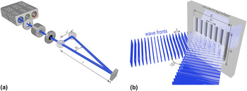
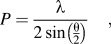
The films were irradiated by the third harmonic 355 nm of a high-energy nanosecond pulse Nd:YAG laser, working at a fundamental wave length of 1064 nm. Pulse duration is 10 ns and repetition rate is set to 10 Hz. The primary laser beam is split into two sub-beams [Fig. 1(a)], which are subsequently focused to interfere on the sample surface [Fig. 1(b)]. A variable attenuator is used to control the laser beam energy delivered from the primary beam. The interference pattern period P is set by tuning the θ angle through l and d, following:
Schematic representation of two-beam interference patterning. (a) shows the path of the laser light through mechanical systems (shutter, beam attenuator and mask) and optical elements (beam splitter and mirror, separated by d). l is the distance between beam-splitter and sample. The output beam is split into two sub-beams through a beam splitter and focused on the sample. (b) represents the interference of the two sub-beams on the sample surface. The wave length (λ) and the angle between the two beams (θ) directly define the structure period (P) in the patterned surface (a 2).

where λ is the wave length of the laser used.
Two-beam interference produces a two-dimensional linear pattern, with a laser intensity distribution I (x) given by:

where c is the speed of light, ε0 the dielectric constant in vacuum, E 0 the electric field amplitude, k the wave number and α, the angle of the beams with respect to the interference plane.
Au-YSZ films were irradiated by single pulses at a laser fluence of 91 mJ/cm2. Two interference pattern periods were fixed to 5 μm and 15 μm. The spot size ‘a’ was set to 2 mm and an area of 25 mm2 was treated for each period by scanning the sample pulse per pulse.
C. Morphological and microstructural characterization
Transmission electron microscopy (TEM) lamellae of Au-YSZ films were prepared by focused ion beam (FIB) before and after LIP to provide details on the structure and microstructure of the samples. The TEM analysis has been carried out with a CM200 Philips microscope. Additionally, scanning electron microscopy (SEM) was used to characterize the effect of LIP treatment on the film surface.
D. Determination of the friction coefficient
Friction coefficients (μ) have been measured using a ball-on-disk nanotribometer (CSM Instruments). Each test has been repeated five times to ensure reproducibility. Tests have been performed on linear reciprocating mode with an alumina ball (dia. = 1.5 mm). Constant normal load (Fn = 1 mN), half amplitude (0.2 mm), number of laps (100 cycles) and linear velocity (0.5 mm/s) have been applied under room temperature (25 °C) and relative humidity above 50%.
E. Analysis of surface roughness
White light interferometry (WLI, New View 200, Zygo) was used to analyze the surface roughness of the patterned films. Abbott–Firestone curves were obtained from the data analyzed with the software Metro Pro. These curves simulate the effect of wear on a bearing surface, representing the depth below a reference level parallel to a solid surface (ordinate) versus the percentage of bearing area intercepted by a horizontal line at that depth (abscissa). Mathematically it is the cumulative probability density function of the height of the surface profile and can be calculated by integrating the profile trace. Skewness (R sk) and kurtosis (R ku) were deduced from the Abbott–Firestone curves. R sk is a measure of the symmetry of the surface profile around the mean line. Negative skew indicates a predominance of valleys, while positive skew indicates a “peaky” surface. A bearing surface should thus exhibit a negative skew. R sk is defined as follows:
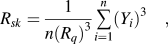
where Y represents the heights of the profile and Rq the root-mean-square roughness (rms).
The kurtosis R ku is given by
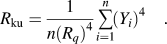
R ku is a measure of the randomness of heights, and of the sharpness of a surface. A perfectly random surface has a value of 3; the farther the result is from 3, the less random and more repetitive the surface is. Surfaces with spikes have higher values; bumpy surfaces exhibit lower values.
III. RESULTS AND DISCUSSION
A. Thermodynamics of the Au-YSZ system
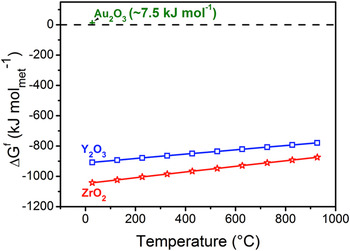
The Gibbs energy of formation of a compound allows evaluating its stability in a given environment. Figure 2 displays the thermal evolution, under 1 bar of air, of the Gibbs energy of formation (ΔGf) of ZrO2 and Y2O3 as well as the standard Gibbs energy of formation of auric oxide Au2O3. The standard value of ΔGf for 1 mol of metal for Au2O3 was taken fromReference Bond13 while the thermal evolutions of ΔGf for 1 mol of metal for ZrO2 and Y2O3 were calculated using the data tabulated inReference Knacke, Kubaschewski and Heselmann14 as follows:


Thermal evolution, under 1 bar of air, of the Gibbs energy of formation of ZrO2, Y2O3 and standard Gibbs energy of formation of Au2O3. The values are given for 1 mol of metal.

Negative values indicate the thermodynamic stability of the compound; the magnitude indicates the reactivity of the metallic element toward oxygen. Given the strongly negative values of ΔGf for ZrO2 and Y2O3, it is expected that Zr and Y will be oxidized in the as deposited state and will remain in this state upon heating. In contrast, gold should be present in the metallic state. Therefore, in contrast to recent observations in the Pd-Zr-Y-O system,Reference Horwat, Zakharov, Endrino, Soldera, Anders, Migot, Karoum, Vernoux and Pierson8 nanocomposite films consisting of gold particles embedded in a YSZ matrix are expected to form by condensing Au, Zr, Y and O atoms as observed in.Reference Voevodin, Hu, Fitz and Zabinski10–Reference Voevodin, Hu, Jones, Fitz and Zabinski12 Furthermore, no chemical reaction should occur upon heating Au-YSZ films, unless the melting point of YSZ (2680 °C) was reached with the LIP treatment.
B. Laser-induced segregation and grain-growth of Au nanoparticles
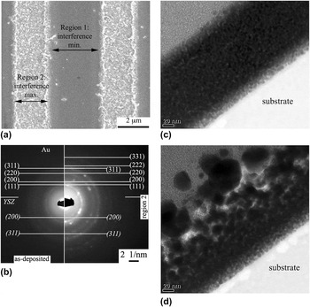
The observation using SEM (Fig. 3) of the film surface after LIP indicates it consists of alternated bands of constant width throughout in each spot. The bands are of two distinct morphologies, namely smooth (region 1) and rough (region 2), and repeated with a period equal to the interference period (P). Using SEM, it was impossible to detect the slightest difference between the surface morphology of the as deposited film and region 1 after LIP. Therefore, regions 1 and 2 correspond to the minima and maxima of interference, respectively. Figure 3(a) shows the surface for the sample treated with P = 5 μm. A typical selected area electron diffraction (SAED) pattern for region 1 is displayed in Fig. 3(b–left). The broad and weak diffraction rings highlight the nanocrystalline character of the coating. These have been ascribed to metallic gold and YSZ. Thus, an Au-YSZ nanocomposite arrangement was formed upon the vapor condensation. This is in line with both the x-ray diffraction analysis conducted by Voevodin et al.Reference Voevodin, Hu, Fitz and Zabinski10–Reference Voevodin, Hu, Jones, Fitz and Zabinski12 on thermally annealed films of similar Au content and with the thermodynamics considerations above. Additionally, the dark spots observed on the corresponding bright-field TEM image in Fig. 3(c) can be ascribed to gold nanoparticles, whose average diameter has been estimated at 6 nm and confirmed by x-ray diffraction analysis (not shown here). The particles are homogeneously dispersed in the YSZ matrix without significant change in the microstructure throughout the film thickness. As observed in Fig. 3(d), LIP had a massive impact on the crystal growth near the surface of the interference maximum zone (region 2). Approximately half of the film thickness is strongly affected by the treatment. Notably, a foamy morphology consisting of gold crystals was formed at the film surface. These changes resulted, not only in an enhanced definition of the electron diffraction rings of Au and YSZ, but also in the presence of well-separated spots for metallic gold [(Fig. 3(b–right)]. Therefore, it is inferred that the local heating induced by LIP triggered a local growth of the gold particles.
Morphology evolution of laser interference-patterned Au-YSZ thin films (a) observed by SEM. Regions 1 and 2 correspond to the laser interference minimum and maximum, respectively. Microstructural investigations of Au-YSZ (b–d). Part (b) displays SAED patterns from the as deposited state (b-left) and region 2 (b-right). Part (c) and (d) provide bright field views in as deposited state and in region 2, respectively (partially reprinted fromReference Catrin, Gries, Horwat, Migot, Mücklich, Endrino, Anders, Andersson, Horwat and Vinnichenko16).

C. Laser-induced reduction of friction coefficient
Friction tests have been performed on pure YSZ and on as deposited and laser-patterned Au-YSZ films. In the case of LIP-treated samples, the sliding direction (parallel or perpendicular to the interference bands) has been considered to study the effect of the anisotropy induced by the laser treatment.
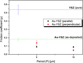
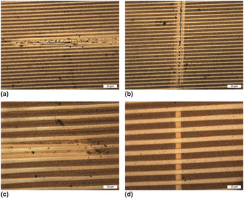
Figure 4 presents the friction coefficient (μ) of a pure YSZ film and of the Au-YSZ nanocomposite films before and after LIP for two structure periods (5 μm and 15 μm) and sliding directions (parallel or perpendicular to the interference bands). The friction coefficient of pure YSZ is quite high at 0.54 ± 0.06. It is observed that the incorporation of gold nanoparticles strongly lowers the value of μ down to 0.18 ± 0.01. After LIP the reduction is even more pronounced (down to 0.051 ± 0.008), which could be ascribed to the partial relocation of Au at the film surface through laser-induced crystal grain growth and diffusion as observed by TEM [(Fig. 3(d)]. This provides a local solid lubrication that matches the observations made by Voevodin et al.Reference Voevodin, Hu, Fitz and Zabinski10–Reference Voevodin, Hu, Jones, Fitz and Zabinski12 on thermally annealed samples. Moreover, both the patterning structure period and the sliding direction appear to significantly influence the friction behavior. For the sliding direction parallel to the interference bands, the structure periods of 5 μm and 15 μm lead to similar values of μ of 0.091 ± 0.008. Compared to sliding tests in the parallel direction, tests perpendicular to the interference bands lead to increased values of μ at P = 5 μm and decreased values at P = 15 μm. It is generally accepted that μ perpendicular < μ parallel.Reference Yuan, Huang and Wang15 Views of the residual wear track after 100 cycles are shown in Fig. 5 for the two structure periods and the two sliding directions. The white bands correspond to the interference maxima and the dark bands to the interference minima. The similarity of results obtained with P = 5 μm and P = 15 μm can be explained through the wear track, which is wider than the patterning period: the sliding ball hardly “feels” the difference between the two geometries. Even though it has not been quantified in this study, the contact areas in the wear track should be equivalent in both cases.
Friction coefficient of Au-YSZ films before and after patterning, depending on the structure period (5 μm and 15 μm) and the sliding direction (parallel or perpendicular). The friction coefficient of a pure YSZ film is given for reference.

Views of the wear track for the two structure periods—5 μm (a, b), 15 μm (c, d)—for both parallel (a, c) and perpendicular (b, d) sliding directions. The scale in the lower right corners corresponds to 20 μm.

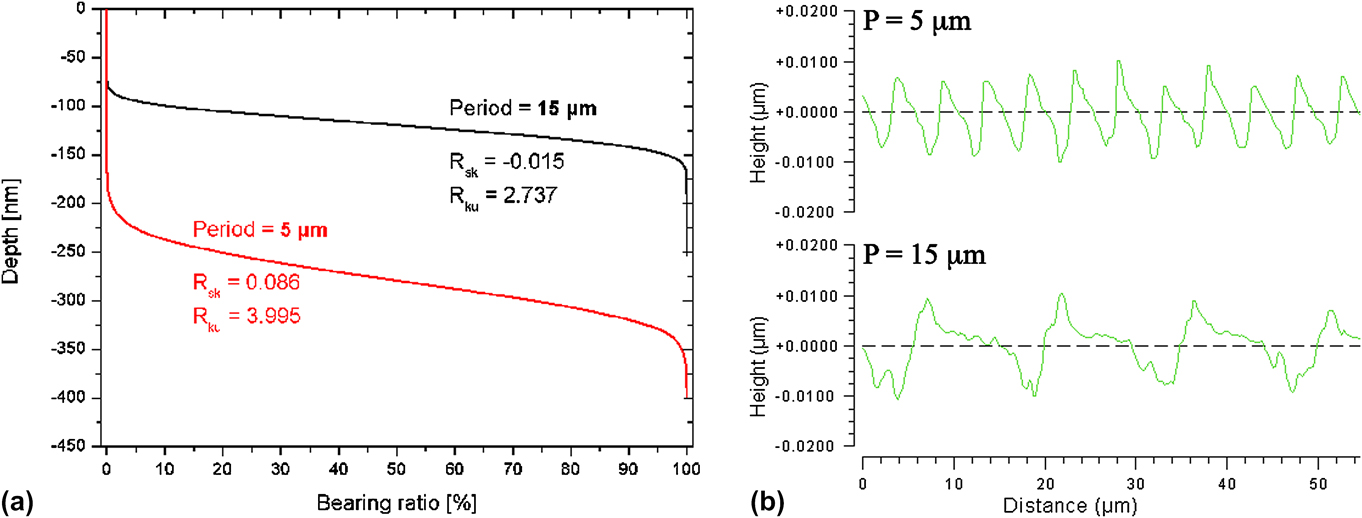
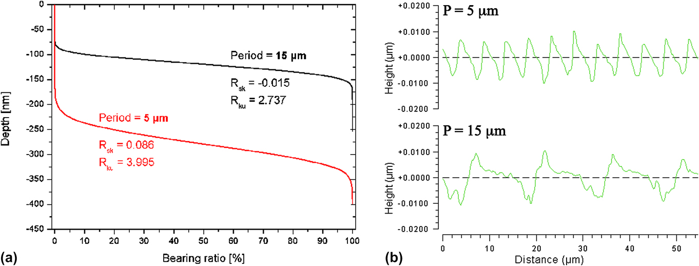
To propose an explanation for the differences resulting from sliding tests perpendicular to the interference bands, the surface roughness of the patterned films was analyzed using WLI; the results are summarized in Fig. 6 in terms of Abbott–Firestone curves [(Fig. 6(a)], R sk, R ku and local surface profiles [Fig. 6(b)]. In the case of the film patterned at 15 μm, R sk presents a negative value (−0.015) and R ku has a positive (2.737). Both values are characteristic of a bumpy bearing surface, which is confirmed by the depth profile in Fig. 6(b). Moreover, the fact that Rku has a value of 2.737, close to 3, indicates the high randomness of the profile. In contrast, the film patterned at 5 μm presents a high value of kurtosis (Rku = 3.995). The surface randomness is low, in accordance with the low structure period, and R sk is positive. Both values are consistent with a peaky surface as seen in Fig. 6(b), which results in high contact pressure. From the Abbott–Firestone curves in Fig. 6(a), it is observed that at similar bearing ratio, the structure at 5 μm should have been damaged to a larger depth. This could have resulted in a prior delamination of the film as observed in Fig. 5(b) and explain the higher friction coefficient in perpendicular sliding for this film.
Calculation of the Abbott–Firestone curves, skewness (R sk) and kurtosis (R ku) for the patterned Au-YSZ with periods of 5 μm and 15 μm (a). Local surface profiles characteristic for the two structure periods (b).
IV. CONCLUSIONS
The influence of LIP on the microstructure of sputter-deposited nanocomposite Au-YSZ thin films with a Au/(Au + Zr + Y) ratio of 0.55 has been investigated by TEM. The gold atoms of Au-YSZ are present in the form of metallic nanograins in a YSZ matrix after deposition, which is consistent with the positive standard enthalpy of formation of auric oxide Au2O3. In the zones of interference maxima, LIP induced a noticeable growth of gold grains near the film surface along with the formation of gold foam at the film surface. Friction tests indicate that the presence of gold nanoparticles in the as deposited state reduces the friction coefficient by a factor of three as compared with pure YSZ. The reduction is even more drastic after LIP treatment was applied. Indeed friction coefficients in the 0.05–0.14 range were achieved depending on the patterning period and sliding direction. The lower friction coefficient after patterning can be explained through the relocation of gold at the film surface and from the surface profile generated by LIP as evidenced from the Abbott–Firestone curves. These results can be of benefit in such of those tribological applications for which dry lubrication is desirable. In contrast to thermal annealing, LIP is a fast and localized process.
ACKNOWLEDGMENTS
The authors acknowledge the German Research Foundation (DFG) for funding under projects MU 959/20–1 and MU 959/20-2 and the BVMatWerk/DFG for the research grant offered for a one year post-doc of T.G. in Germany.