


1. Introduction
A jet in cross-flow (JICF) is widely used in energy and propulsion systems (Karagozian Reference Karagozian2010), where a jet is injected into a cross-flow. There are complex interactions between the jet and cross-flow, which can increase the mixing efficiency and enhance reaction rates in practical combustors. There has been an increasing interest in lean premixed combustion, which can lower combustion temperature and reduce NO $_x$ emissions. For a jet of premixed mixtures injected into a vitiated hot cross-flow, the interactions between the jet flame and complex vortices influence the flame stabilization behaviour and subsequent flame dynamics. However, existing understanding of premixed reacting jets in cross-flow is largely insufficient, which motivates the present study.
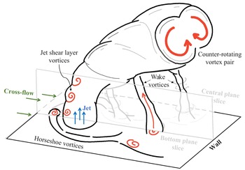
Previous experimental studies have revealed the vortical systems of non-reacting JICFs (Fric & Roshko Reference Fric and Roshko1994). A schematic of typical vortical structures is shown in figure 1. It is observed that, when the wall boundary layer encounters the jet, horseshoe vortices wrapping around the base of the jet are generated (Baker Reference Baker1980). Jet shear layer vortices are found at the jet/cross-flow boundary as a result of the Kelvin–Helmholtz instability (Yuan & Street Reference Yuan and Street1998; Sauerwein & Vakili Reference Sauerwein and Vakili1999). A counter-rotating vortex pair (CVP) forms in the near field and becomes dominant in the far field with mixing enhancement (Moussa, Trischka & Eskinazi Reference Moussa, Trischka and Eskinazi1977; Cortelezzi & Karagozian Reference Cortelezzi and Karagozian2001). The tornado-like wake vortices have terminations on the wall and the main jet column in the downstream region of the jet due to the entrainment of the cross-flow boundary layer by the jet (Fric & Roshko Reference Fric and Roshko1994). Recent studies based on numerical simulations of JICFs showed good agreement with experimental data and provided statistics of quantities that are not available from experiments. For example, Muppidi & Mahesh (Reference Muppidi and Mahesh2005, Reference Muppidi and Mahesh2006, Reference Muppidi and Mahesh2007, Reference Muppidi and Mahesh2008) used direct numerical simulation (DNS) data of a JICF, built upon experiment (Su & Mungal Reference Su and Mungal2004), to analyse the characteristics of the jet trajectory, turbulence structure and passive scalar transport.
Typical vortical structures in a non-reacting jet in cross-flow.

There are also some studies of reacting JICFs in the literature, most of which focused on non-premixed reacting JICFs. For example, Steinberg et al. (Reference Steinberg, Sadanandan, Demb, Kutne and Meier2013) studied the mechanisms of flame stabilization of a preheated H $_2$/N
 $_2$ fuel jet injected into a heated air cross-flow. A similar configuration was investigated by Grout et al. (Reference Grout, Gruber, Yoo and Chen2011) using DNS. The authors found that the lifted windward flame was unsteady and the leeward flame stabilized in a low-velocity region between the large CVP where the mixture was near stoichiometric. Schlegel & Ghoniem (Reference Schlegel and Ghoniem2014) simulated a pure methane jet in a cross-flow using a hybrid Eulerian/Lagrangian approach. They observed a triple flame structure on the leeward side and drew the conclusion that the flame seats in a region of relatively low scalar dissipation rate. Further investigations have examined the effects of parameters, including momentum flux ratio (Batchelor, Howells & Townsend Reference Batchelor, Howells and Townsend1959; Steinberg et al. Reference Steinberg, Sadanandan, Demb, Kutne and Meier2013; Sullivan et al. Reference Sullivan, Wilde, Noble, Seitzman and Lieuwen2014) and jet injection angle (Han & Mungal Reference Han and Mungal2003; Kolla et al. Reference Kolla, Grout, Gruber and Chen2012), on the flow field and the flame location of non-premixed reacting JICFs.
More recently, due to the regulation of pollutant emissions, there has been a trend for combustion engineers to develop premixed combustion technologies, and fundamental studies of premixed reacting JICFs have attracted considerable interest. Schmitt et al. (Reference Schmitt, Kolb, Weinzierl, Hirsch and Sattelmayer2013) experimentally examined a jet of premixed propane–air mixtures injected into a fuel-lean vitiated cross-flow. Chemiluminescence imaging showed that the jet ignites immediately upon entering the hot cross-flow, and the flame length and shape are related to the equivalence ratio. Later, Wagner et al. (Reference Wagner, Grib, Renfro and Cetegen2015) used simultaneous particle image velocimetry (PIV) and planar laser-induced fluorescence (PLIF) imaging of OH and CH $_2$O to study a rich premixed ethylene–air reacting JICF. The flow fields of the non-reacting and reacting JICF were characterized, and two stabilization locations of the flame, i.e. one on the windward side and the other on the leeward side, were identified. In their follow-up studies, the flame behaviours of the premixed reacting JICF with varying equivalence and momentum ratios were investigated (Wagner et al. Reference Wagner, Grib, Dayton, Renfro and Cetegen2017a; Wagner, Renfro & Cetegen Reference Wagner, Renfro and Cetegen2017b; Dayton, Linevitch & Cetegen Reference Dayton, Linevitch and Cetegen2019). These studies suggested that auto-ignition is the dominant flame stabilization mechanism for the unsteady windward flame, and premixed flame propagation is dominant for the leeward flame. Large-eddy simulations (LES) (Schulz & Noiray Reference Schulz and Noiray2019; Schulz et al. Reference Schulz, Piccoli, Felden, Staffelbach and Noiray2019; Solana-Pérez, Schulz & Noiray Reference Solana-Pérez, Schulz and Noiray2021) were performed based on the experiment of Wagner et al. (Reference Wagner, Grib, Renfro and Cetegen2015) and the spatio-temporal evolution of the auto-ignition process along the windward mixing layer was analysed.
In the above-mentioned studies, the flame structures and stabilization mechanisms were widely studied. However, the complex interactions between turbulence and the flame of premixed reacting jets in cross-flow have not been investigated in detail yet due to the challenges of capturing small-scale structures by experiments and LES. Therefore, DNS is employed in the present work to study the turbulence and flame structures, and provide detailed information of turbulence–flame interactions.
The interactions between turbulence and scalar fields are important features of turbulent combustion. The scalar gradient is a key quantity in describing and modelling turbulent mixing and combustion. The process of scalar gradient generation/dissipation by turbulence has been used to characterize turbulence–flame interactions. This process can be understood by the alignment of the principal strain rates and the scalar gradient. Early investigations (Batchelor Reference Batchelor1952; Batchelor et al. Reference Batchelor, Howells and Townsend1959; Kerr Reference Kerr1985; Nomura & Elghobashi Reference Nomura and Elghobashi1992) of turbulence–scalar interactions in non-reacting flows showed that passive scalar gradients preferentially align with the most compressive principal strain rate. Such interactions become more complex in reacting flows due to the effects of heat release, which are governed by the relative importance of the chemical process and the flow dynamics. Accordingly, a Damköhler number ( $Da$) was introduced to classify various regimes of turbulent premixed flames, which is defined as the ratio of large-scale turbulence time to the characteristic flame time. In flames with a
 $Da$ larger (smaller) than unity, the chemical process is faster (slower) than the turbulence process (Poinsot & Veynante Reference Poinsot and Veynante2001). The effects of
 $Da$ on the alignment characteristics in premixed flames have been studied. It was reported that the reactive scalar gradient aligns with the most extensive principal strain rate in premixed turbulent flames with a large
 $Da$ (Steinberg, Driscoll & Swaminathan Reference Steinberg, Driscoll and Swaminathan2012; Sponfeldner et al. Reference Sponfeldner, Boxx, Beyrau, Hardalupas, Meier and Taylor2015; Zhao et al. Reference Zhao, Er-raiy, Bouali and Mura2018). As for flames with a low
 $Da$ and high
 $Ka$ (Karlovitz number), the reactive scalar gradient has a tendency to align with the most compressive strain rate (Kim & Pitsch Reference Kim and Pitsch2007; Wang, Hawkes & Chen Reference Wang, Hawkes and Chen2016; Wang et al. Reference Wang, Hawkes, Ren, Chen, Luo and Fan2021b), similar to the behaviour of the passive scalar gradient in non-reacting flows. However, the alignment characteristics are not fully understood for the moderate and low
 $Da$ regime, where the separation of chemical and turbulence scales is not strictly valid.
Most of the previous studies used a global  $Da$ for the analyses of turbulence–flame interactions. However, for configurations with complex turbulence and flame structures, turbulence–flame interactions are dependent on the local
 $Da$ of various flame zones, which has rarely been investigated. The local values of
 $Da$ along the flame fronts in turbulent premixed ethylene–air flames stabilized by a bluff body were measured experimentally by Hartung et al. (Reference Hartung, Hult, Kaminski, Rogerson and Swaminathan2008). It was found that the flame normal aligns with the most compressive strain rate in the regions where
 $Da < 1$ and the alignment is influenced by curvature. Grout et al. (Reference Grout, Gruber, Kolla, Bremer, Bennett, Gyulassy and Chen2012) investigated the effects of local
 $Da$ of a non-premixed reacting JICF. The preferential alignment between the scalar gradient and the most compressive strain was found throughout the jet with moderate local
 $Da$. In a premixed reacting JICF, the flow–flame structures show significant difference in various locations, so that a local
 $Da$ is required to characterize the complex interactions of the flow and flame.
The alignment characteristics also have impacts on the normal ( $a_n$) and tangential (
 $a_t$) strain rates of the flame. The former yields the generation/dissipation of the scalar gradient, and the latter implies the stretching of the flame front. The preferential alignment of the scalar gradient and the most extensive strain rate could result in a positive
 $a_n$, which tends to diminish the scalar gradient; conversely, a negative
 $a_n$ related to the scalar gradient aligning with the compressive strain rate tends to enhance the scalar gradient (Dopazo et al. Reference Dopazo, Cifuentes, Martin and Jimenez2015). Extensive tangential strains act to increase the flame surface area. The effects of
 $a_t$ on the flame structures of turbulent premixed combustions have been widely studied (Candel & Poinsot Reference Candel and Poinsot1990; Poinsot Reference Poinsot1992; Echekki & Chen Reference Echekki and Chen1996; Matalon Reference Matalon2009; Wang et al. Reference Wang, Hawkes, Chen, Zhou, Li and Aldén2017b).
Curvature is an important parameter related to turbulence–flame interactions. The statistics of curvature, twice the value of the mean curvature  $k_m$, have been reported in many studies (Echekki & Chen Reference Echekki and Chen1996; Sankaran et al. Reference Sankaran, Hawkes, Chen, Lu and Law2007; Chakraborty et al. Reference Chakraborty, Hawkes, Chen and Cant2008; Sankaran et al. Reference Sankaran, Hawkes, Yoo and Chen2015; Wang et al. Reference Wang, Hawkes, Chen, Zhou, Li and Aldén2017b) in various configurations. The mean curvature is correlated with the tangential strain rate, both of which have impacts on the flame stretching (Candel & Poinsot Reference Candel and Poinsot1990; Chen & Im Reference Chen and Im2000) in turbulent combustion. Wang et al. (Reference Wang, Hawkes, Chen, Zhou, Li and Aldén2017b) studied a premixed jet flame using DNS and found that high positive tangential strain-rate regions generally correspond with low-curvature regions, and these regions tend to be positively stretched. In addition to the mean curvature, the Gauss curvature
 $k_g$ has also been used to depict the local shape of the flame surface. Dopazo, Martín & Hierro (Reference Dopazo, Martín and Hierro2006, Reference Dopazo, Martín and Hierro2007) used DNS data of constant-density turbulent flows to characterize the local geometry of scalar iso-surfaces in terms of
 $k_m$ and
 $k_g$. Cifuentes et al. (Reference Cifuentes, Dopazo, Martin and Jimenez2014) investigated turbulence–flame interactions by examining the local geometry of reactive scalar iso-surfaces. They found that positive volumetric dilatation rates display a maximum for elliptic concave structures and a minimum for convex structures.
In this context, the configuration of a lean premixed jet flame in cross-flow was considered in the present work. The experimental configuration of Dayton et al. (Reference Dayton, Linevitch and Cetegen2019) was investigated. Considering the increasing interest for lean premixed combustion with low combustion temperatures, the experimental case with an equivalence ratio  $\phi = 0.6$ was chosen. In a recent work (Cheng et al. Reference Cheng, Wang, Luo and Fan2022), we reported a DNS study of this flame for the first time, where the DNS results were compared with those of the experimental measurements, with promising agreement, and the flame stabilization mechanism of the laboratory-scale premixed jet flame in cross-flow was reported. In the present work, a non-reacting case under the same conditions was also considered for comparison to explore the effects of combustion on the flow field. In addition to presenting the flow and flame structures, the interactions between the scalar fields and turbulence were analysed, which has not been reported before in the literature for such flame configurations.
The contents of the present article are as follows. First, the configuration of the JICF and the numerical methods of the DNS are described. Second, the flow structures of the non-reacting and reacting cases are studied, and the effects of heat release on the flow field are emphasized. The turbulent flame structure is analysed and compared with the laminar flame structure. The interactions between turbulence and the flame are investigated by analysing the local  $Da$, strain rate and curvature of the flame front. Finally, conclusions are made.
2. Configuration and numerical methods
The DNS configuration is based on the experiment of Dayton et al. (Reference Dayton, Linevitch and Cetegen2019). A jet of ethylene–air mixture with an equivalence ratio of  $\phi = 0.6$ is injected perpendicularly into a vitiated cross-flow under atmospheric pressure. The jet temperature is 300 K. The jet diameter is
 $d = 9.53$ mm and the jet velocity
 $U_j$ is 9.95 m s
 $^{-1}$. The jet Reynolds number based on
 $d$ and
 $U_j$ is 6161. The cross-flow is generated by a propane–air flame with an equivalence ratio of 0.87 and the cross-flow temperature is 1500 K. The cross-flow velocity is
 $U_{cf} = 7.6$ m s
 $^{-1}$. The characteristics of the JICF largely depend on the jet-to-cross-flow momentum ratio (
 $J$), which is defined as
 \begin{equation} J=\frac{\rho_{j}{U_j^2}}{\rho_{cf}{U_{cf}^2}}, \end{equation}
where  $\rho _j$ and
 $\rho _{cf}$ denote the density of the jet and cross-flow, respectively. In the present work, the jet-to-cross-flow momentum ratio is
 $J = 8.7$. The corresponding laminar flame velocity
 $S_L$ under the same conditions of the jet is 0.23 m s
 $^{-1}$, the flame thermal thickness
 $\delta _L$ is 0.562 mm and the flame time scale
 $\tau _L = \delta _L/S_L$ is 2.44 ms. The flame thermal thickness is defined using the temperature profile as
 $(T_2-T_1)/{\max (\partial {T}/\partial {x})}$, where
 $T_1$ and
 $T_2$ are the temperatures of the reactant and the product, respectively. From the experiment, no information about the wall temperature was available; the wall temperature in the present work is consistent with the cross-flow temperature.
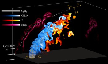
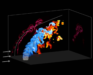
Figure 2 shows the configuration of the reacting JICF and the volume renderings of scalar fields. Two DNS cases of non-reacting and reacting JICFs are considered. The configurations of the two DNS cases is consistent. However, in the non-reacting case, chemical reactions are turned off artificially.
Schematic diagram of the configuration of the reacting JICF and volume rendering of temperature and species of the DNS. The distributions of heat release rate from the central  $x$–
 $y$ plane and a
 $y$–
 $z$ plane in the downstream region are also shown.

The cross-flow is modelled as a laminar flow over a flat plate in the DNS. At the inflow plane, the velocity profile is specified according to the solution of the Blasius equation for laminar boundary layer flows (Hermann Schlichting Reference Hermann Schlichting1987). The free-stream velocity of the laminar boundary layer flow is the same as  $U_{cf}$. In the absence of the jet, the laminar boundary layer thickness is
 $\delta = 0.5d$ at the plane of
 $x/d = 0$ (note that
 $x/d$ ranges from
 $-1$ to 9 in the DNS configuration). The species mass fractions of the cross-flow are determined from a chemical equilibrium calculation of propane–air mixture at a temperature of 1500 K, i.e.
 $Y_{{\rm N}_2} = 0.724$,
 $Y_{{\rm CO}_2} = 0.160$,
 $Y_{{\rm H}_2{\rm O}} = 0.087$ and
 $Y_{{\rm O}_2} = 0.029$.
The mean jet velocity profile at the inlet is not available from the measurement. In the DNS, it is specified using a power-law velocity profile for fully developed turbulent pipe flows (Yamaguchi Reference Yamaguchi2008). A turbulence field is obtained by generating a homogeneous isotropic turbulence field based on a prescribed Passot–Pouquet energy spectrum (Passot & Pouquet Reference Passot and Pouquet1987). The turbulent velocity  $u^\prime$ is 10 % of
 $U_j$ and the integral length scale
 $l_t$ is half of
 $d$. The homogeneous isotropic turbulence field is added to the mean jet velocity using Taylor's hypothesis. The inlet temperature and species are specified by the following profile:
 \begin{equation} \psi=\psi_{cf}+\frac{\psi_{j}-\psi_{cf}}{2} \left(1+\tanh\left(\frac{d/2-r}{\delta_{s}}\right)\right), \end{equation}
where  $\psi _{j}$ and
 $\psi _{cf}$ denote the values of a scalar
 $\psi$ in the jet and the cross-flow, respectively. The symbol
 $r$ is the radial distance, and
 $\delta _s$ is the characteristic thickness for scalar variations.
The physical domain for the DNS is  $L_x \times L_y \times Lz = 10d \times 6d \times 8d$ in the streamwise direction (
 $x$), wall-normal direction (
 $y$) and spanwise direction (
 $z$). The origin of the coordinates is located at the centre of the jet exit. For the main simulation, the boundary condition is non-reflecting for the inflow (
 $x = -1d$) and outflow (
 $x = 9d$,
 $y = L_y$ and
 $z = 0/L_z$) planes, and no-slip isothermal wall boundary
 $(y = 0)$. The grid spacing is chosen to adequately resolve both the flame and turbulence structures. The grids are uniform, with
 ${\rm \Delta} {x} = {\rm \Delta} {y} ={\rm \Delta} {z} =55\ \mathrm {\mu }{\rm m}$ in the region of
 $x/d = -1$ to
 $5$,
 $y/d = 1$ to
 $5$ and
 $z/d = -2$ to
 $2$, covering most of the flame regions. The grids are gradually stretched outside of this region, with a maximum grid size of
 $d$/100, namely 95
 $\mathrm {\mu }$m. Algebraic stretching is used in three directions, with a maximum relative stretching rate under 2.5 %. Approximately 10 grid points across
 $\delta _L$ are obtained with this spatial resolution, which is considered sufficient for capturing the flame structure in DNS (Hesse, Chakraborty & Mastorakos Reference Hesse, Chakraborty and Mastorakos2009; Hawkes et al. Reference Hawkes, Chatakonda, Kolla, Kerstein and Chen2012; Wang et al. Reference Wang, Chen, Luo, Hawkes, Chen and Fan2021a). The resolution is validated using one-dimensional tests with different grid resolutions. Figure 3 shows the profiles of heat release rate obtained with grid resolutions of 30
 $\mathrm {\mu }$m, 55
 $\mathrm {\mu }$m, 80
 $\mathrm {\mu }$m and 100
 $\mathrm {\mu }$m. Note that the flames are initialized for different resolutions by interpolation from a fine mesh solution (20
 $\mathrm {\mu }$m), and then evolved for 15 flame times. The position of the flames has not been adjusted, so that the difference between the profiles results from the cumulative error during the simulation. As can be seen, the difference between the heat release rate profiles of the flames with
 ${\rm \Delta} {x} = 30\ \mathrm {\mu }$m and 55
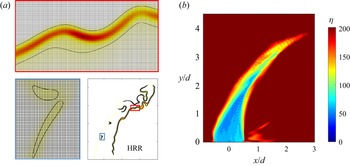
 $\mathrm {\mu }$m is negligible. Therefore, the resolution of the present work is sufficient for resolving the flame structure. Figure 4(a) shows the distributions of heat release rate for the reacting case, where the grids are superimposed. It is clear that both the ignition kernels of the windward branch and the leeward flame are well resolved using the current resolution. The Kolmogorov length scale
 $\eta$ is the lowest in a narrow region of the windward shear layer, as shown in figure 4(b). The minimum value of
 $\eta$ is 43
 $\mathrm {\mu }$m, so that the criterion
 $\eta /{\rm \Delta} {x}>0.5$ (Pope Reference Pope2000) is satisfied everywhere in the computational domain. The resultant number of grids is
 $N_x \times N_y \times N_z = 1504 \times 1040 \times 960$.
The profiles of heat release rate (HRR) of the one-dimensional premixed flame with different grid resolutions.

The distributions of (a) heat release rate (J m $^{-3} {\rm s}^{-1}$) with the presence of grid structure on typical reaction zones and (b) Kolmogorov length scales (
 $\mathrm {\mu }$m) of the reacting case in the central
 $x$–
 $y$ plane.

It is useful to describe the evolution of the jet in a coordinate system that is aligned with the jet centre, as shown in figure 2. At every point along the jet trajectory (defined as the streamline with an origin from the jet centre), a new coordinate system ( $s,n,m$) is defined, where
 $s$ is the direction tangential to the jet trajectory,
 $n$ is the direction normal to the trajectory in the
 $x$–
 $y$ plane, and
 $m$ is the spanwise direction normal to both
 $s$ and
 $n$.
The DNS code ‘S3D’ (Chen et al. Reference Chen2009) was employed to solve the compressible transport equations for continuity, momentum, species mass fractions and total energy. The code uses a fourth-order Runge–Kutta method for time integration (Kennedy, Carpenter & Lewis Reference Kennedy, Carpenter and Lewis2000) and a skew-symmetric, eighth-order explicit finite difference spatial scheme. A tenth-order filter was applied every 10 time steps to damp high-wavenumber oscillations. The DNS code has been used widely for studies of turbulent combustion (Yoo, Sankaran & Chen Reference Yoo, Sankaran and Chen2009; Grout et al. Reference Grout, Gruber, Yoo and Chen2011; Wang, Hawkes & Chen Reference Wang, Hawkes and Chen2017a; Wang et al. Reference Wang, Chen, Luo, Hawkes, Chen and Fan2021a). A reduced mechanism (Yoo et al. Reference Yoo, Richardson, Sankaran and Chen2011) of C $_2$H
 $_4$ combustion with 22 species and 206 elementary reactions is used in the present DNS. The mechanism has been validated comprehensively against the detailed mechanism, with good agreement in a variety of configurations, including perfectly stirred reactors, auto-ignition and laminar premixed flames (Luo et al. Reference Luo, Yoo, Richardson, Chen, Law and Lu2012). The mechanism is included in the supplementary material, which is available at https://doi.org/10.1017/jfm.2023.78. The simulations were advanced for 4
 $\tau _j$ after reaching a statistically steady state, where
 $\tau _j$ is the jet time estimated as
 $\tau _j = d/U_j$.
3. Results and discussion
3.1. Flow structures
The DNS results have been validated by comparing against the experimental measurements of various quantities, including the jet trajectory, temperature distribution and lift-off height in another paper focusing on validation and flame stabilization (Cheng et al. Reference Cheng, Wang, Luo and Fan2022). In this section, the characteristics of the flow structures are demonstrated, with the emphasis on the difference between the non-reacting and reacting DNS cases.
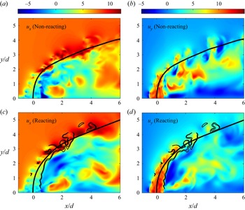
Figure 5 shows the instantaneous distributions of the streamwise velocity ( $u_x$) and the wall-normal velocity (
 $u_y$) in the central
 $x$–
 $y$ plane of the non-reacting and reacting cases. The distribution of the streamwise velocity is closely related to the cross-flow and jet behaviours. In particular, when the cross-flow encounters the jet, shear layer vortices appear and the magnitude of
 $u_x$ significantly decreases in front of the jet. It is shown that the region with high values of
 $u_x$ approaches the jet trajectory with the development of the jet, that is, the values of
 $u_x$ increase along the jet trajectory in the downstream region of the jet. It is also shown that the leeward side is close to regions with negative values of
 $u_x$ in the near field of the jet, which indicates the entrainment of the cross-flow.
The instantaneous distributions of the streamwise and wall-normal velocities (m s $^{-1}$) of the non-reacting (top) and reacting (bottom) cases in the central
 $x$–
 $y$ plane. The trajectories of the jets and the reaction zone of the reacting case are denoted by the black solid lines.

The distribution of the wall-normal velocity shows that the jet characterized by large values of  $u_y$ is considerably influenced by the cross-flow, which highlights the role of cross-flow in improving the mixing between the jet and the ambient flow. The chemical reactions in the reacting case lead to gas expansion, providing an additional momentum for the jet to resist the cross-flow, and result in a deeper penetration of the reacting jet into the cross-flow. The shear layer, especially on the leeward side, of the reacting jet is weaker than that of the non-reacting jet, due to an increase of the flow viscosity around the flame. It is worth noting that a recirculation zone with negative values of
 $u_y$ is found in the wake of the jet in the reacting case. This recirculation zone will be characterized in more detail later.
The reaction zone identified by the iso-line of heat release rate at 10 % of the maximum heat release rate in the corresponding laminar flame is superimposed on the velocity fields of the reacting case as shown in figure 5. The windward flame locates in the shear layer and ignites where the cross-flow interacts with the jet. In contrast, the leeward branch of the flame anchors in the shear layer near the jet exit. A detailed analysis of ignition and flame behaviours is beyond the scope of the present work, but has been explored in Cheng et al. (Reference Cheng, Wang, Luo and Fan2022).
The distributions of the mean velocity magnitude in the central  $x$–
 $y$ plane are shown in figure 6. The mean velocity magnitude is defined as
 $U_{mag}=\sqrt {U_x^2+U_y^2+U_z^2}$, where
 $U_x$,
 $U_y$ and
 $U_z$ are the mean velocity components in the
 $x$,
 $y$ and
 $z$ directions, respectively. Note that the value of
 $U_z$ is zero in the central
 $x$–
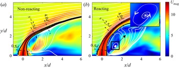
 $y$ plane. On the windward side, a stagnation region is observed ahead of the jet. The stagnation region is formed as a result of the jet acting as an obstruction to the cross-flow. The width of the non-reacting jet, demonstrated by the black streamlines emanating from the edges of the jet exit, decreases along the jet trajectory and the two streamlines approach in the downstream region. This is in contrast with the reacting jet, where the jet is more robust. Previous studies of JICFs have found that the entrainment rates decrease when combustion is present (Han & Mungal Reference Han and Mungal2001; Hasselbrink & Mungal Reference Hasselbrink and Mungal2001). The decrease of the entrainment rates slows down the decay of the jet and allows the reacting jet to be more robust compared to the non-reacting jet.
The distributions of the mean velocity magnitude (m s $^{-1}$) of the (a) non-reacting and (b) reacting cases in the central
 $x$–
 $y$ plane. The solid lines represent the streamlines and the dashed lines mark the locations of the cross-planes examined in the following.

The flow structures on the leeward side differ between the non-reacting and reacting cases, as shown in figure 6. In the non-reacting case, the mean flow is mostly characterized by upright streamlines. The fluids of the cross-flow flow around the jet to the leeward side, and those close to the jet are entrained and pulled away from the wall (Fric & Roshko Reference Fric and Roshko1994), forming upright vortices. It is apparent that a strong recirculation zone locates behind the reacting jet. The reduction of the entrainment rates in the reacting case results in more cross-flow fluid in the wake to recirculate during the interactions between the flame and flow field. The high-temperature product of the leeward combustion is trapped in the recirculation zone, which facilitates the stabilization of the flame.
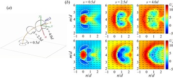
The distributions of  $U_s$ in the cross-planes normal to the trajectory are displayed to reveal the jet evolution shown in figure 7. Here,
 $U_s$ is the mean velocity in the
 $s$ direction, which is computed as
 $U_s = \boldsymbol {U} \boldsymbol {\cdot } \boldsymbol {n}_{s}$, where
 $\boldsymbol {U}$ is the mean velocity vector and
 $\boldsymbol {n}_{s}$ is the unit vector in the
 $s$ direction. The cross-planes of
 $s = 0.5d$, 2.5
 $d$ and 4
 $d$ are chosen for the analysis to characterize the different stages of the jet development, as shown in figure 7(a). The three planes are also marked in figure 6. At
 $s = 0.5d$, regions with a negative
 $U_s$ appear in both the non-reacting and reacting cases as a consequence of the entrainment of the cross-flow. The jet at
 $s = 0.5d$ is oval-shaped. The in-plane velocity vectors are superimposed to depict the flow structure. It can be seen that the CVP is not formed yet at
 $x = 0.5d$ and the shear turbulence dominates the mixing process. As for the behaviour of the wake, a region with positive values of
 $U_s$ is located behind the non-reacting jet, resulting from the entrainment in the upright vortices, as described earlier, while a recirculation zone with negative values of
 $U_s$ is shown in the wake of the reacting jet. A kidney-like shape of the jet is observed at
 $s = 2.5d$. The in-plane velocity vectors suggest that the CVP dominates over the shear vortices at this location. The non-reacting jet decays significantly at
 $s = 4d$. In contrast, the decay of the reacting jet is delayed.
(a) The schematic of the jet evolution. (b) The distributions of the mean velocity (m s $^{-1}$) in the
 $s$ direction in the cross-planes of
 $s = 0.5d$,
 $s = 2.5d$ and
 $s = 4d$ of the non-reacting (top) and reacting (bottom) cases. The in-plane velocity vectors are also shown. The dashed circle with a centre on the trajectory and diameter of
 $d$ denotes the notional nozzle, and the white line is the iso-line of
 $U_s = 0$.

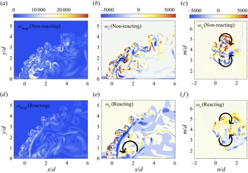
The vorticity magnitudes of the non-reacting and reacting cases on the central  $x$–
 $y$ and normal planes are shown in figure 8. The vorticity magnitude is defined as
 $\omega _{mag}=\sqrt {\omega _x^2+\omega _y^2+\omega _z^2}$, where
 $\omega _x$,
 $\omega _y$ and
 $\omega _z$ represent the vorticity components in the
 $x$,
 $y$ and
 $z$ directions, respectively. In the non-reacting case, the vortices produced due to Kelvin–Helmholtz instability on the windward side correspond to large vorticity magnitudes. The vorticity magnitude in the wake of the jet is also large, which indicates the good mixing on the leeward side. The magnitude of the vorticity in the reacting case is generally lower compared with that in the non-reacting case due to the thermal effects from combustion.
The distributions of the (a,d) vorticity magnitude (s $^{-1}$) and (b,e) spanwise vorticity (s
 $^{-1}$) on the central
 $x$–
 $y$ plane, and (c,f) the
 $s$ axis vorticity in the cross-plane of
 $s = 2.5d$.

The contour of  $\omega _z$ of the central
 $x$–
 $y$ plane is also shown and the directions of flow rotation are marked in figure 8. Negative values of
 $\omega _z$ are found near the wall ahead of the jet, indicating the location where the horseshoe vortex is formed. The vortices in the shear layer on the windward side are shown with high positive values of
 $\omega _z$ and in the leeward shear layer with negative
 $\omega _z$. The vortical structures on the leeward side of the non-reacting jet are complex, while the recirculation zone is dominant in the wake of the reacting jet.
The CVP has been shown to be responsible for the far-field entrainment in the downstream region of the jet; therefore, the cross-plane of  $s = 2.5d$ is chosen for the analysis of
 $\omega _s$, i.e. the vorticity component in the
 $s$ direction. It is obvious that the CVP contributes to turbulent mixing over a wide range of the space. The area of the CVP in the reacting case is larger due to the dilatation, but the strength is weaker.
3.2. Turbulent flame structures
Before showing the turbulent flame structures of the reacting case, the corresponding freely propagating laminar flame under the same conditions as the premixed jet is presented. The distributions of heat release rate, temperature and species mass fractions are shown in figure 9. It is seen that the flame structure consists of three distinct zones, i.e. a preheat zone, a reaction zone and a post-flame zone. The species CH $_2$O acts as a marker of the preheat zone with a rising temperature but low heat release rate. The location of the peak mass fraction of CO overlaps with that of the maximum heat release rate, which represents the reaction zone. The post-flame zone is characterized by high temperature and high OH concentration. Moreover, it can be inferred that the product of CH
 $_2$O and OH mass fractions serves as a good heat release rate surrogate, which is helpful to the identification of the flame front using experiments, where direct measurements of heat release rate are impossible (Paul & Najm Reference Paul and Najm1998; Wang et al. Reference Wang, Hawkes, Zhou, Chen, Li and Aldén2017c).
The flame structures of the corresponding one-dimensional laminar flame.

Figure 10 shows the instantaneous distributions of heat release rate, temperature and species mass fractions in the central plane of the reacting DNS case. The reaction zone is superimposed to indicate the location of the flame. It is seen that the heat release rate is weak on the windward side due to the high strain of the shear turbulence, and is significantly higher in the reaction zone of the leeward side. The temperature is low in the centre of the jet and elevated by turbulent mixing and chemical reactions at the jet edges. A region with high temperature is found after the leeward reaction zone.
The instantaneous distributions of (a) heat release rate (HRR, J m $^{-3}\ {\rm s}^{-1}$), (b) temperature (
 $T$, K) and (c–f) species mass fractions of the reacting case in the central
 $x$–
 $y$ plane. The reaction zone is denoted by the solid line on the scalar fields.

The distributions of species mass fractions are consistent with the reaction processes for the laminar flame. The regions with high concentrations of CH $_2$O represent the preheat zone. It is also found that the preheat zone is thickened by the shear layer vortices, particularly in the downstream region. The CO species mainly distributes in the reaction zone and its concentration is higher on the leeward side compared with the windward side. The OH species represents the post-flame zone located next to the reaction zone. A region with higher mass fractions of OH is found on the leeward side.
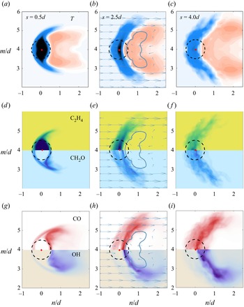
The distributions of mean scalars in different cross-planes are shown in figure 11 to understand the evolution of the jet flame and its correlations with the flow structures. At  $s = 0.5d$, the edges of the oval-shaped jet with a low temperature and high C
 $_2$H
 $_4$ mass fraction are stretched by the cross-flow. There are two flame branches, i.e. the windward and leeward branches, around the jet core. A high-temperature region appears in the wake of the jet. In the downstream region of
 $s = 2.5d$, the magnitude of temperature increases and the high-temperature region becomes wider. The distributions of scalars are influenced by the CVP, which acts as the dominant vortical structure and results in a crescent-like shape of the windward and leeward branches. The recirculation zone is filled with high-temperature product, which facilitates the reactions of the leeward flame. In the further downstream region of
 $s = 4d$, the temperature further increases and the fuel is mostly consumed. The distributions of scalars are similar to those of
 $s =2.5d$, with the two flame branches being closer and more product accumulating in the post-flame zone.
The distributions of the mean scalars of the reacting case in the cross-planes of  $s = 0.5d$,
 $s = 2.5d$ and
 $s = 4d$, where the colour bars of the scalar contours are consistent with those in figure 10. The dashed circle with a centre on the trajectory and diameter of
 $d$ denotes the notional nozzle. The in-plane velocity vectors and the iso-line of
 $u_s = 0$ are denoted in the cross-plane of
 $s = 2.5d$.

In order to provide more quantitative results, the mean heat release rate and mass fractions of species of the reacting case conditioned on temperature are shown in figure 12. The conditional means from both the windward and leeward sides on the cross-planes are plotted. The profiles of the corresponding laminar flame are also presented for comparison. It is seen that the heat release rate of the windward flame increases with increasing values of  $s$, and is lower than that of the leeward side. The maximum heat release rate of the leeward flame is found at
 $s = 2.5d$, while that of the windward flame is found at
 $s = 4d$.
The flame structures of the reacting case conditionally averaged on the temperature of  $s = 0.5d$ (dotted), 2.5
 $d$ (dashed) and 4
 $d$ (solid). The flame structures of the corresponding laminar flame are also presented for comparison.

As shown in figure 12, there is an evident difference between the flame structures of the turbulent case and the laminar one. In particular, the heat release rate and species mass fractions of the turbulent case are lower than its laminar counterpart. This is expected, as the turbulent flame is influenced by the strain rate resulting from shear turbulence in the JICF configuration. Wang et al. (Reference Wang, Hawkes and Chen2017a) also showed similar results in a high- $Ka$ jet flame and compared the mean structure of the flame with that of strained laminar flames to explain this flame behaviour. Another fact is that the windward flame branch is dominant by auto-ignition instead of a steady propagating flame (Wagner et al. Reference Wagner, Grib, Dayton, Renfro and Cetegen2017a; Schulz et al. Reference Schulz, Piccoli, Felden, Staffelbach and Noiray2019), whose mean flame structure is not expected to match a freely propagating flame.
3.3. Interactions between turbulence and the flame
From the above analysis, it is concluded that the turbulent flame structure is significantly different from that of the corresponding laminar flame, which indicates the complex interactions between turbulence and the flame. In this section, the turbulence–flame interactions are examined via the statistics of the local  $Da$, strain rate and curvature of the flame front.
A progress variable,  $c$, is defined to measure the progress of reaction based on the mass fraction of a major species:
 \begin{equation} c=\frac{Y-Y_{j}}{Y_{cf}-Y_{j}},\end{equation}
where  $Y_{j}$ is the species mass fraction in the jet and
 $Y_{cf}$ is the species mass fraction in the cross-flow. According to the definition,
 $c$ increases monotonically from zero in the jet to unity in the cross-flow.
Figure 13(a) shows the instantaneous distributions of the progress variable defined based on different species, including C $_2$H
 $_4$, O
 $_2$, CO
 $_2$ and H
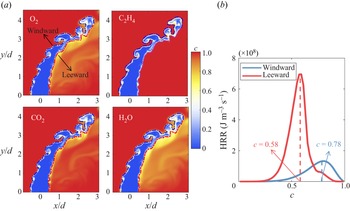
 $_2$O, where the blue and red lines delineate the instantaneous flame fronts on the windward and leeward side, respectively. It is seen that the instantaneous flame fronts in figure 13(a) are almost identical based on various species mass fractions. The progress variable based on the O
 $_2$ mass fraction has been commonly used (Sankaran et al. Reference Sankaran, Hawkes, Chen, Lu and Law2007; Wang et al. Reference Wang, Hawkes and Chen2017a) and it is employed in this work. Different values of the progress variable are used for identifying the different flame branches. In particular, the instantaneous flame front is defined as
 $c = 0.78$ on the windward side and
 $c = 0.58$ on the leeward side, corresponding to the peak heat release rate values, as shown in figure 13(b). We note that the progress variable of the product in the corresponding freely propagating premixed flame is not unity. According to the oxygen mass fraction in the product of the freely propagating premixed flame, the value of the progress variable in the product is 0.69 using (3.1). The product is further mixed with the cross-flow until the progress variable reaches unity. The premixed flame structure is also influenced by the cross-flow, as shown in figure 13(b), so that it is more reasonable to define the progress variable using the oxygen mass fraction of the cross-flow rather than that of the product of the freely propagating premixed flame.
(a) Instantaneous contours of the progress variable based on different definitions. (b) The mean heat release rate conditioned on the progress variable based on O $_2$ mass fraction.

A similar definition of the progress variable can also be defined for the non-reacting case, as the O $_2$ mass fraction of the non-reacting case also varies from
 $Y_{j}$ in the jet to
 $Y_{cf}$ in the cross-flow, although no reactions are involved in this case. In order to make a consistent comparison between the reacting and non-reacting cases where applicable,
 $c$ and
 $\boldsymbol {n}$ are also defined for the non-reacting case in the same way as for the reacting case. Here,
 $\boldsymbol {n}$ is the flame normal vector defined as
 $\boldsymbol {n} = -\boldsymbol {\nabla }{c}/|{\boldsymbol {\nabla }{c}}|$.
3.3.1. Time scales and local  $Da$

In the present work, the global  $Da$ of the premixed jet of the reacting case, calculated as
 $(l_t / u^\prime )/\tau _L$, is 1.96, while a local
 $Da$ needs to be examined for its variations in various regions of the premixed reacting JICF configuration. Lu et al. (Reference Lu, Yoo, Chen and Law2010) proposed a
 $Da$ defined based on the time scales of the chemical explosive mode (CEM) and the local instantaneous scalar dissipation rate, which indicates how fast the explosive mode is compared with mixing. In addition to the configuration of jet flames (Lu et al. Reference Lu, Yoo, Chen and Law2010; Luo et al. Reference Luo, Yoo, Richardson, Chen, Law and Lu2012), it has also been employed in a non-premixed reacting JICF (Grout et al. Reference Grout, Gruber, Kolla, Bremer, Bennett, Gyulassy and Chen2012). Following this definition, the flow and chemical time scales and local
 $Da$ are investigated.
The scalar dissipation rate  $\chi$ provides a useful local time scale, which is defined as 2
 $D|\boldsymbol {\nabla }{Z}|^2$, where
 $Z$ is the mixture fraction and
 $D$ is the thermal diffusivity. It is noted that the equivalence ratios of the jet and cross-flow streams are different, so that a mixture fraction can be defined, which is calculated based on the Bilger's method (Bilger, Stårner & Kee Reference Bilger, Stårner and Kee1990) as follows:
 \begin{gather} Z=\frac{\beta-\beta_{cf}}{\beta_{j}-\beta_{cf}}, \end{gather}
 \begin{gather}\beta=2\frac{\gamma_{\rm C}}{W_{\rm C}}+\frac{1}{2}\frac{\gamma_{\rm H}}{W_{\rm H}}-\frac{\gamma_{\rm O}}{W_{\rm O}}, \end{gather}
where  $\gamma$ and
 $W$ are the elemental mass fraction and atomic mass for the elements carbon, hydrogen and oxygen, respectively. In (3.3),
 $\beta _j$ and
 $\beta _{cf}$ are the values of
 $\beta$ in the jet and cross-flow streams, respectively, and it is obvious that
 $Z$ is unity in the jet and is zero in the cross-flow. The instantaneous distributions of the scalar dissipation rate in the central
 $x$–
 $y$ plane and cross-plane of
 $s = 2.5d$ are shown in figure 14. On the windward side, the scalar dissipation rate is high in the shear layer, corresponding to a high scalar gradient and large heat loss, which results in a relatively low heat release rate, as shown in figure 12. It is worth noting that the regions with a large value of
 $\chi$ are usually concave to the reactant. As for the leeward side, the scalar dissipation rate is relatively large near the jet exit and decreases in the downstream region, which is much lower compared with the windward side.
The instantaneous distributions of scalar dissipation rate (s $^{-1}$) in (a) the central
 $x$–
 $y$ plane and (b) the cross-plane of
 $s = 2.5d$.

To further understand the characteristics of  $\chi$, the probability density functions (p.d.f.s) of
 $\log _{10}\chi$ conditioned on the flame front at various downstream locations are presented in figure 15(a). As can be seen, the most probable value of
 $\chi$ on the windward side decreases with increasing
 $s$ due to the decay of the turbulent strains in the shear layer. As for the leeward side, the p.d.f.s are found to be broader, with a lower most probable value of
 $\chi$ compared with those on the windward side, which indicates that the characteristic flow time scale is larger on the leeward side. The most probable value of
 $\chi$ on the leeward side also decreases along the jet trajectory.
The p.d.f.s of (a) the logarithm of  $\chi$ of the scalar iso-surfaces of
 $s = 0.5d$ (dotted), 2.5
 $d$ (dashed) and 4
 $d$ (solid), and (b) the normalized logarithm of
 $\chi$ of
 $s = 2.5d$ compared with a Gaussian distribution.

The p.d.f.s of  $\log _{10}\chi$, normalized by its mean
 $\mu$ and root mean square
 $\sigma$, at
 $s = 2.5d$ are plotted along with Gaussian distributions as shown in figure 15(b). It is found that the distribution of
 $\chi$ is nearly log-normal, consistent with that in non-reacting jet experiments (Su & Clemens Reference Su and Clemens2003) and DNS of jet flames (Hawkes et al. Reference Hawkes, Sankaran, Sutherland and Chen2007, Reference Hawkes, Sankaran, Chen, Kaiser and Frank2009). The normalized p.d.f.s slightly depart from a Gaussian distribution, and are negatively skewed. The p.d.f.s on the leeward side follow the Gaussian distribution more closely compared with those on the windward side.
As for the chemical time scale, a brief introduction to CEM analysis (Lu et al. Reference Lu, Yoo, Chen and Law2010) is provided first. The transport equation for the chemical source term  $\omega (\boldsymbol {y})$ can be written as
 \begin{equation} \frac{{\rm D} \omega(\boldsymbol{y})}{{\rm D} t}={J_\omega} \frac{{\rm D} \boldsymbol{y}}{{\rm D} t}={J_\omega}(\omega+f), \end{equation}
where  $\boldsymbol {y}$ is the vector that includes species mass fractions and temperature,
 $J_\omega$ is the chemical Jacobian (
 $J_\omega = {\rm D}\omega /{\rm D}\boldsymbol {y}$) and
 $f$ is the diffusion term. The eigenvalue of
 $J_\omega$ associated with the most explosive mode, i.e. the eigenvalue with the largest positive real part, is denoted as
 $\lambda _e$, which reflects the inverse time scale of the most explosive mode. The CEM is a chemical property of the local mixture with positive
 $\lambda _e$, indicating the propensity of the mixture to ignite if it is isolated. The burnt region usually presents no CEM with negative
 $\lambda _e$, which leads to negative
 $Da$ under this definition. Instantaneous distributions of
 $\lambda _e$ in the central
 $x$–
 $y$ plane and cross-plane of
 $s = 2.5d$ are shown in figure 16. Note that the magnitude of
 $\lambda _e$ can be very large, so that
 ${\rm {sign}}(\lambda _e) \times {\log _{10}} (\max (1,|{\lambda _e}|))$ is shown here instead, where ‘sign’ is the sign function, and the value of sign
 $(\lambda _e)$ is +1 (
 $-$1) when
 $\lambda _e$ is positive (negative). Large positive values of
 $\lambda _e$ are found around the reaction zone on both sides, and the values are larger on the leeward side. The transition from the region with significant positive
 $\lambda _e$ to that with negative values is abrupt, indicating a propagating front or ignition front, which is consistent with the results of the experiment (Dayton et al. Reference Dayton, Linevitch and Cetegen2019) showing that auto-ignition and premixed flame propagation dominate the windward and leeward flames, respectively.
The instantaneous distributions of sign $(\lambda _e) \times {\log _{10}}(\max (1,|{\lambda _e}|))$ in (a) the central
 $x$–
 $y$ plane and (b) the cross-plane of
 $s = 2.5d$.

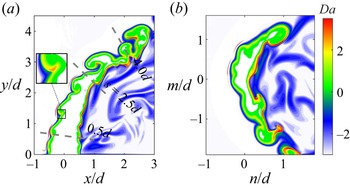
The local  $Da$ is defined as sign
 $(\lambda _e) \times {\log _{10}} (\max (1,|\lambda _e \chi ^{-1}|))$ based on the flow and chemical time scales discussed above (Lu et al. Reference Lu, Yoo, Chen and Law2010), and its distribution is shown in figure 17. On the windward side, a positive
 $Da$ is found in the shear layer and its value is higher in the regions with a high positive curvature, corresponding to the reaction zone with high heat release rate. The correlation between
 $Da$ and curvature will be discussed in more detail later. On the leeward side, a thin region with a large positive
 $Da$ along the jet edge appears.
The instantaneous distributions of local  $Da$ in (a) the central plane and (b) the cross-plane at
 $s = 2.5d$.

The mean values and p.d.f.s of the local  $Da$ conditioned on the flame front at various downstream locations are shown in figure 18. It is observed that the mean value of
 $Da$ on the windward side is slightly larger than unity and increases with increasing
 $s$, while that on the leeward side is larger and has a maximum at
 $s = 2.5d$. Furthermore, the p.d.f.s show that the possibility of
 $Da < 1$ is high on the windward side, especially in the upstream region of
 $s =0.5d$, consistent with the high turbulence intensity and weak reaction rate. As for the leeward side, the local
 $Da$ is generally higher than unity, but it is still a problem of moderate
 $Da$ (
 $Da < 10$), whose effects on the turbulence–flame interactions need to be further studied.
The mean values and p.d.f.s of the local  $Da$ conditioned on the flame fronts of
 $s = 0.5d$ (dotted), 2.5
 $d$ (dashed) and 4
 $d$ (solid).

3.3.2. Strain rate and alignment characteristics
In this subsection, the turbulence–flame interactions are quantified by the alignment between the scalar gradient (flame normal) and strain rates, which has been found to depend strongly on  $Da$ in different configurations (Hartung et al. Reference Hartung, Hult, Kaminski, Rogerson and Swaminathan2008; Minamoto et al. Reference Minamoto, Fukushima, Tanahashi, Miyauchi, Dunstan and Swaminathan2011). The results are interpolated to the flame front, and both reacting and non-reacting cases are analysed based on the scalar iso-surfaces to explore the effects of chemical reactions on the alignment characteristics.
In turbulent flows, small-scale structures may be described in terms of the strain-rate tensor  $\boldsymbol{\mathsf{S}}_{ij}$, which is defined as
 \begin{equation} \boldsymbol{\mathsf{S}}_{ij}=\frac{1}{2}\left(\frac{\partial{u_i}}{\partial{x_j}}+ \frac{\partial{u_j}}{\partial{x_i}}\right), \end{equation}
where  $u_i$ is the
 $i$th component of the instantaneous velocity. The tensor
 $\boldsymbol{\mathsf{S}}_{ij}$ can be characterized by its principal eigenvalues
 $\lambda _1$,
 $\lambda _2$ and
 $\lambda _3$, designated by the convention
 ${\lambda _1}\ge {\lambda _2}\ge {\lambda _3}$, which are determined from the following characteristic equation of
 $\boldsymbol{\mathsf{S}}_{ij}$:
 \begin{equation} \lambda^3+P{\lambda^2}+Q\lambda+R=0, \end{equation}
where  $P$,
 $Q$ and
 $R$ are the three invariants of
 $\boldsymbol{\mathsf{S}}_{ij}$, i.e.
 \begin{gather} P=-\boldsymbol{\mathsf{S}}_{ii}, \end{gather}
 \begin{gather}Q=\tfrac{1}{2}({\boldsymbol{\mathsf{S}}_{ii}}^2-\boldsymbol{\mathsf{S}}_{ij}{\boldsymbol{\mathsf{S}}_{ji}}), \end{gather}
 \begin{gather}R={-}\tfrac{1}{6}({\boldsymbol{\mathsf{S}}_{ii}}^3-3{\boldsymbol{\mathsf{S}}_{ii}}{\boldsymbol{\mathsf{S}}_{jk}}{\boldsymbol{\mathsf{S}}_{kj}} +2{\boldsymbol{\mathsf{S}}_{ij}}{\boldsymbol{\mathsf{S}}_{jk}}{S_{ki}}). \end{gather}
The eigenvectors of  $\lambda _1$,
 $\lambda _2$ and
 $\lambda _3$ are
 $\boldsymbol {e}_{1}$,
 $\boldsymbol {e}_{2}$ and
 $\boldsymbol {e}_{3}$, respectively.
Figure 19 shows the p.d.f.s of the principal eigenvalues of the strain-rate tensor,  $\lambda _i$. It is obvious that
 $\lambda _1$ (
 $\lambda _3$) is mainly positive (negative), and the distribution of
 $\lambda _2$ is slightly positively skewed with a near-zero most probable value, which is consistent with many previous DNS results (Ashurst et al. Reference Ashurst, Kerstein, Kerr and Gibson1987; Wang et al. Reference Wang, Hawkes and Chen2016). The magnitude of the principal strain rates decreases with increasing
 $s$ on both sides. The principal strain-rate magnitude is generally larger on the leeward side of the non-reacting case compared with the reacting case.
The p.d.f.s of  $\lambda _i$ of
 $s = 0.5d$ (dotted), 2.5
 $d$ (dashed) and 4
 $d$ (solid) of the non-reacting case (a) and reacting case (b).

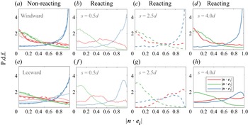
The p.d.f.s of  $|{\boldsymbol {n}}\boldsymbol {\cdot }{\boldsymbol {e}_{i}}|$ conditioned on the flame front at various downstream locations are shown in figure 20. It can be seen that the scalar gradient preferentially aligns with the most compressive strain rate,
 $\boldsymbol {e}_{3}$, on both sides of the non-reacting case. Accordingly, there is a tendency for
 $\boldsymbol {n}$ to point away from
 $\boldsymbol {e}_{1}$ and
 $\boldsymbol {e}_{2}$. This observation is consistent with previous studies of passive scalars in turbulent flows (Kerr Reference Kerr1985; Nomura & Elghobashi Reference Nomura and Elghobashi1992).
The p.d.f.s of  $|{\boldsymbol {n}}\boldsymbol {\cdot }{\boldsymbol {e}_{i}}|$ at
 $s = 0.5d$ (dotted), 2.5
 $d$ (dashed) and 4
 $d$ (solid) of the non-reacting case (a,e) and reacting case (b–d,f–h).

The alignment characteristics on the windward side of the reacting case are similar to those of the non-reacting case. As for the leeward side, the increased trend of the flame normal aligning with the most extensive strain rate is evident due to the higher heat release rate compared with the windward side. Notably, the flame normal exhibits a predominant alignment with the most extensive strain rate at  $s = 2.5d$.
The difference between the two cases suggests that the dilatation induced by chemical reactions, which acts on the normal direction of the scalar iso-surface, can influence the alignment characteristics. It is also found that generally the region with a higher value of  $|{\boldsymbol {n}}\boldsymbol {\cdot }{\boldsymbol {e}_{1}}|$ corresponds to a larger mean value of local
 $Da$ on the leeward side, as shown in figure 18. This observation is consistent with the study of Steinberg et al. (Reference Steinberg, Driscoll and Swaminathan2012), which analysed the influence of the mean
 $Da$ in Bunsen flames, and that of Hartung et al. (Reference Hartung, Hult, Kaminski, Rogerson and Swaminathan2008), which measured the local
 $Da$. A larger value of
 $Da$ is related to a higher dilatation, resulting in an increased tendency of the scalar gradient being aligned with the most extensive strain rate.
The normal strain rate,  $a_n$, defined as
 $n_i{\boldsymbol{\mathsf{S}}_{ij}}n_j$, is related to the alignment characteristics:
 \begin{equation} a_n=\lambda_1{|{\boldsymbol{n}}\boldsymbol{\cdot}{\boldsymbol{e}_{1}}|}^2 +\lambda_2{|{\boldsymbol{n}}\boldsymbol{\cdot}{\boldsymbol{e}_{2}}|}^2 +\lambda_3{|{\boldsymbol{n}}\boldsymbol{\cdot}{\boldsymbol{e}_{3}}|}^2.\end{equation}
The tangential strain rate,  $a_t$, is given by
 $\boldsymbol {\nabla } \boldsymbol {\cdot }\boldsymbol {u}- a_n$, where
 $\boldsymbol {\nabla } \boldsymbol {\cdot }\boldsymbol {u}$ is the dilatation. The distributions of the dilatation in the central
 $x$–
 $y$ plane of the non-reacting and reacting cases are investigated in figure 21. In the non-reacting case, the value of dilatation is large in the shear layer of both sides and is small in the wake of the jet. Both positive and negative dilatations can be found. As for the reacting case, the characteristics of the dilatation on the windward side are similar to those of the non-reacting case, while only large positive dilatation can be found around the reaction zone of the leeward side due to the strong heat release rate.
The distributions of the dilatation (s $^{-1}$) of the non-reacting and reacting cases in the central
 $x$–
 $y$ plane.

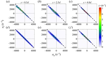
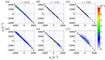
The joint p.d.f.s of the normal and tangential strain rates conditioned on the flame front at various downstream locations of the non-reacting and reacting cases are then shown in figures 22 and 23, respectively. As shown in figure 22, a high probability occurs in the regions with a positive  $a_t$ and a negative
 $a_n$ on the windward side of the non-reacting case. The windward jet edge is stretched by the cross-flow, which is responsible for the positive
 $a_t$. Meanwhile, the fluid elements are compressed in the normal direction. The scalar iso-surfaces are brought together and the scalar gradient is enhanced, which is reflected by the negative
 $a_n$. These observations can also be explained by the preferential alignment shown in figure 20: the negative
 $\lambda _3{|{\boldsymbol {n}}\boldsymbol {\cdot }{\boldsymbol {e}_{3}}|}^2$ acts as the dominant term in (3.10), producing a negative
 $a_n$. The regions with a large positive
 $a_t$ and a negative
 $a_n$ tend to occur more infrequently with increasing
 $s$, which is related to the reduced
 $\lambda _3$ shown in figure 19.
The joint p.d.f.s of the normal and tangential strain rates of the non-reacting case. Panels (a–c) are the windward results and (d–f) the leeward results.

The joint p.d.f.s of the normal and tangential strain rates of the reacting case. Panels (a–c) are the windward results and (d–f) the leeward results.

It is worth noting that a large portion of the flow in the non-reacting case is below the line of  $a_n + a_t = 0$, which corresponds to the regions with negative dilatations on the windward side, as shown in figure 21. This is due to the fact that the fluid elements are compressed when the cross-flow interacts with the jet. Near-zero dilatations with relatively small values of strain rates are observed on the leeward side, due to the weaker shear compared with the windward side.
As shown in figure 23, the characteristics of  $a_n$ and
 $a_t$ on the windward side of the reacting case are similar to those of the non-reacting case, especially in the upstream region, due to the minor effects of the low heat release rate. Note that positive dilatations appear in the regions that have a positive
 $a_n$ and a negative
 $a_t$ in the downstream region. As for the leeward side, the probabilities of a positive
 $a_n$ increase and a positive
 $a_t$ decrease compared with the windward side. In addition, nearly all the flame elements exhibit positive dilatations, which is consistent with figure 21. Moreover, the product of
 $\lambda _1$ and
 ${|{\boldsymbol {n}}\boldsymbol {\cdot }{\boldsymbol {e}_{1}}|}^2$ becomes important in the reacting case, as shown in figure 20, which is responsible for the increasing probabilities of a positive
 $a_n$ and dilatation compared with the non-reacting case.
3.3.3. Local geometries of scalar iso-surface
Curvature is another parameter that influences the local structure of the flame. The curvature tensor is  $\boldsymbol{\mathsf{n}}_{i,j}=\partial {n_i}/\partial {x_j}$, where
 $n_i$ is the
 $i$th component of the flame normal
 $\boldsymbol {n}$. The invariants of
 $\boldsymbol{\mathsf{n}}_{i,j}$ are given by
 \begin{gather} I_1={-}\boldsymbol{\nabla} \boldsymbol{\cdot}\boldsymbol{n}, \end{gather}
 \begin{gather}I_2=\tfrac{1}{2}(\boldsymbol{\mathsf{n}}_{i,i}{\boldsymbol{\mathsf{n}}_{j,j}}-\boldsymbol{\mathsf{n}}_{i,j}{\boldsymbol{\mathsf{n}}_{j,i}}), \end{gather}
 \begin{gather}I_3=-{\det(\boldsymbol{\mathsf{n}}_{i,j})}. \end{gather}
As  $I_3 = 0$, the two eigenvalues of
 $\boldsymbol{\mathsf{n}}_{i,j}$ (main curvatures,
 $k_1$ and
 $k_2$) are obtained from the equation
 \begin{equation} k^2+I_1{k}+I_2=0. \end{equation}
The Gauss curvature,  $k_g$, and the mean curvature,
 $k_m$, are
 \begin{equation} k_g=k_1{k_2},\quad k_m=\frac{k_1+{k_2}}{2}=\frac{1}{2} \frac{\partial{n_i}}{\partial{x_i}}. \end{equation}
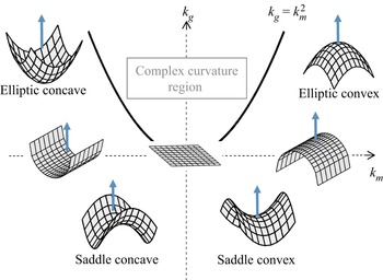
Figure 24 shows the different local geometries of the flame surface in terms of the mean and Gauss curvatures. The zone of  $k_g>{k_m}^2$ in the
 $k_m$–
 $k_g$ plane implies non-physical complex curvatures. For a positive (negative) mean curvature, i.e.
 $k_m > 0$ (
 $k_m < 0$), the surface is convex (concave) towards the fresh reactant. For a positive (negative) Gauss curvature, i.e.
 $k_g > 0$ (
 $k_g < 0$), the surface shows an elliptic (saddle) shape. For a zero Gauss curvature, i.e.
 $k_g = 0$, the surface shows a locally cylindrical shape. The surface is flat for
 $k_m = {k_g} = 0$.
Schematic of the classification of scalar iso-surface geometries in terms of their mean and Gauss curvatures.

The joint p.d.f.s of the mean and Gauss curvatures of the flame front for the reacting case at  $s = 2.5d$ are presented in figure 25. Similar characteristics of the local geometries are obtained on other cross-planes, which are not shown here. On the windward side, the high-probability region is skewed towards negative
 $k_m$ and positive
 $k_g$, indicating that the flame front is mainly concave towards the fresh reactant with elliptic local shapes. In contrast, the mean value of curvature on the leeward side is close to zero.
The joint p.d.f.s of the normalized mean and Gauss curvatures of the flame front of the reacting case at  $s = 2.5d$.

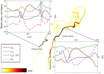
Curvature is correlated closely with the local  $Da$, as noted in figure 17. These correlations are further investigated. The variations of the strain rate, curvature and local
 $Da$ along the flame front of typical regions are shown in figure 26. In general,
 $a_t$ is negatively correlated with
 $a_n$ and
 $k_m$ on both sides. A negative correlation between
 $a_t$ and
 $k_m$ has been found in previous studies of premixed turbulent flames (Kim & Pitsch Reference Kim and Pitsch2007; Sankaran et al. Reference Sankaran, Hawkes, Yoo and Chen2015; Wang et al. Reference Wang, Hawkes and Chen2017a). Regions with a high local
 $Da$ on the windward side of the reacting case correspond to high positive curvature regions. On the leeward side, the correlation of the local
 $Da$ and other parameters is not evident.
The variations of the strain rate, curvature and local  $Da$ on the flame front of the reacting case.

4. Conclusions
The three-dimensional DNS of an experimental lean premixed reacting jet in cross-flow (JICF) was analysed to understand the flow–flame structures and turbulence–flame interactions. It was shown that the jet acts as an obstacle to the cross-flow, and the shear layer is formed at the jet edge. The windward flame of the reacting case locates in the shear layer and ignites where the cross-flow interacts with the jet. In contrast, the leeward branch of the flame anchors in the shear layer near the jet exit. The reacting jet penetrates deeper into the cross-flow and is more robust compared with the non-reacting jet. As for the behaviours of the wake, the entrainment of the cross-flow by the non-reacting jet results in upright vortices in the wake, while a recirculation zone is formed behind the reacting jet due to the reduction of the entrainment rate. The evolutions of the jet were also demonstrated. The cross-section of the jet is oval-shaped in the upstream regions, and is deformed to a kidney-like shape with the decay of the velocity when a counter-rotating vortex pair (CVP) becomes the dominant mixing structure in the downstream region. The decay of the jet is delayed in the reacting case.
The flame structures of the reacting case were explored. The heat release rate is weak on the windward side and is significantly higher in the reaction zone of the leeward side. The preheat zone, reaction zone and post-flame zone are characterized by the mass fraction of CH $_2$O, CO and OH, respectively. The distributions of the scalars are dependent on the reaction process and the flow patterns. In particular, a crescent-like shape of the windward and leeward branches was found in the downstream region due to the influence by the CVP. Moreover, the recirculation zone is filled with high-temperature product, which facilitates the reactions of the leeward flame. An evident difference between the flame structures of the reacting JICF and those of the corresponding laminar flame was observed, due to the turbulence strain and the unsteady auto-ignition flame.
The turbulence–flame interactions were scrutinized, and the local  $Da$ on the flame front of the reacting case was examined. On the windward side, a positive
 $Da$ is found in the shear layer, and its value is higher in the regions with a large positive curvature, corresponding to the reaction zone with a high heat release rate. On the leeward side, a thin region with a large positive
 $Da$ along the jet edge appears. It was also observed that the mean value of
 $Da$ on the windward side is slightly larger than unity and increases with increasing
 $s$, while that on the leeward side is larger and has a maximum at
 $s = 2.5d$. The alignment characteristics between the scalar gradient and strain rates were found to be dependent on the local
 $Da$. The large values of local
 $Da$ are related to the dilatation induced by chemical reactions, resulting in an increased tendency of the scalar gradient to align with the most extensive strain rate.
The alignment characteristics have direct impacts on the tangential and normal strain rates. Negative dilatation regions with a positive tangential strain rate and a negative normal strain rate are observed on the windward side of the reacting case. High positive dilatations appear on the flame front of the leeward side. The analysis of the local geometries showed that the scalar iso-surface is mainly concave towards the fresh reactant, with elliptic local shapes on the windward side of the reacting case. In contrast, the mean value of curvature on the leeward side is close to zero. It was also found that  $a_t$ is negatively correlated with
 $a_n$ and
 $k_m$ on both sides. Regions with a high local
 $Da$ on the windward side of the reacting case correspond to high positive curvature regions. On the leeward side, the correlation of local
 $Da$ and other parameters is not evident.
We note that the DNS is based on an experimental configuration relevant to advanced combustion technologies, and more studies are required to fully understand the physics involved in such flames. The present work explores the flow and flame structures in detail and highlights the complex turbulence–flame interactions, which provides useful understanding of a reacting JICF.
Supplementary material
Supplementary material is available at https://doi.org/10.1017/jfm.2023.78.
Funding
This work was supported by Natural Science Foundation of China (grant nos. 52022091, 51976185 and 91841302). The work was also supported by the Fundamental Research Funds for the Central Universities, China (grant no. 2021FZZX001-10).
Declaration of interests
The authors report no conflict of interest.