1. Introduction
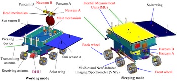
The lunar surface modes of Yutu-2 [Reference Ma, Liu, Sima, Wen, Peng and Jia1, Reference Ma, Peng, Jia and Liu2] are divided into a working mode and a sleeping mode, as shown in Fig. 1. During its operation, Yutu-2 will experience the lunar night (lasting approximately two Earth weeks) during which the temperatures will fall to as low as −180°C. Due to the lack of illumination during the lunar night, the solar cell on the wings cannot provide sufficient power. To avoid these super low-temperature and nonillumination issues, engineers must set the sleeping mode for Yutu-2 before entering the lunar night. In the actual setup process of the sleeping mode for Yutu-2, the rover pose (the yaw angle
 $\gamma _{y}$
, the pitch angle
 $\gamma _{p}$
and the roll angle
 $\gamma _{r}$
) plays a key role. There are two major considerations with respect to the application performance for the equipment on the Yutu-2 rover: the solar wing and the radioisotope heater unit (RHU) [Reference Wang and Liu3].
Lunar surface modes of Yutu-2.

-
1. In the thermal testing of Yutu-2 on Earth, the left solar wing operated well in situations when the angle between the light and the plane of the left solar wing (
 $\vartheta$
) was more than 15.0 degrees; then, at that point the rover will be awakened. Hence, to ensure that the requirement of the angle
$\vartheta$
is satisfied, the roll angle of the rover must be adjusted. When Yutu-2 wakes up, the temperature of the equipment must not be either too low or too high. If the rover leans too far to the left, it will be awakened too early, just after the sun rises. In that case, some of the equipment cannot work properly due to the low temperature. If the rover tilts too much to the right, it will be awakened when the sun has risen too much. In that case, the temperature could be beyond a limit, and the equipment on board would not work properly.
-
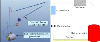
2. Yutu-2 has a RHU that provides 120 W of thermal power [Reference Wang and Liu3]. An RHU is a small device that provides heat through radioactive decay. RHUs are especially useful on the Moon because of its lengthy and cold two-week night. Yutu-2 needs to survive on the lunar surface for a long time, and this requires that the temperature control task during the lunar night be completed successfully. In the Chang’e-4 (CE-4) mission, a gas–liquid thermal control system (TCS) was placed in Yutu-2 to transmit the thermal energy to various parts of Yutu-2 with maximum efficiency, as shown in Fig. 2.


Left: 3D model of the heat and electricity cogeneration system; right: Composition of the TCS.

Figure 2 shows how the waste heat of the radioisotope thermoelectric generator (RTG) is centralized and dispersed. The TCS is connected to the RTG through a plate evaporator, which collects waste heat and transmits it into the cabin. If there is a rotation angle deviation in Yutu-2, the TCS will be adversely affected. As shown in Fig. 2, there is a height difference between the accumulator and the plate evaporator. Hence, the liquid flow in the TCS is driven by the one-sixth of the gravity on the moon’s surface. The ammonia circulates through a control valve, a pipeline, into the plate evaporator, in which the liquid ammonia is vaporized, and then to a condenser, where the gaseous ammonia is converted to a liquid and the heat is reabsorbed by the cabin. If the accumulator is not higher than the plate evaporator due to the incline angle of the rover body, the liquid ammonia cannot flow to the plate evaporator. Hence, the Yutu-2 rover must be placed on level ground to ensure that the TCS is positioned approximatively horizontal.
As described above, due to the requirements of the solar wing and [Reference Wang and Liu3] the requirements of the TCS, the rover pose must satisfy certain limits prior to entering the Yutu-2 rover sleeping mode. As the lunar night approaches, the rover must stop working. If, at that the moment, the measured angles of Yutu-2 in the current position do not meet the above three conditions, the result will be an extremely large drain on the energy supply. Hence, the rover must adjust its pose before entering the lunar night. Due to the construction characteristics of the rover, the servo system cannot change the shape or reduce the height of one side of the wheels. In that case, the rover cannot adjust the pose by using the servo system. However, there are two other methods to adjust the rover pose. The first method is that the rover digs a hole in the lunar surface at the current position by using the wheels. The second method is by moving to a new location where the rover pose can match the required attitude conditions. Due to work efficiency and equipment security, the second method is the better choice. Hence, the problem of searching for a rover pose that exactly meets the requirements is the key to the rover’s remote operating system. Accurate pose prediction of Yutu-2 before entering the sleeping mode is critical for short-term path planning [Reference Wang, Wan, Gou, M.Peng, Di, Li, Yu, Wang and Cheng4], attitude control of the rover, and instrumentation setting in the lunar mission, which will save the Yutu-2 rover’s energy, improve the work efficiency and reduce the risk of the lunar exploration project.
Due to the narrow scope of this area of interest, research on the pose prediction method for a planetary rover has not been studied before, while research has mainly been focused on simultaneous visual localization and mapping (SLAM) [Reference Ma, Liu, Sima, Wen, Peng and Jia1, Reference Geromichalos, Azkarate, Tsardoulias, Gerdes, Petrou and Pulgar5–Reference Qing, Chuang, Bo, Shuo, Lei and Song9], path planning [Reference Wang, Wan, Gou, M.Peng, Di, Li, Yu, Wang and Cheng4, Reference Zhang, Xia and Shen10–Reference Krüsi, Furgale, Bosse and Siegwart13] and visual prediction of terrain occlusion [Reference Ma, Peng, Jia and Liu2]. In a real planetary environment, the research of the planetary rover’s pose prediction has mainly been focused on how to realize a rover’s perception and positioning. To accomplish the goal of setting the sleeping mode for the rover, the surrounding information obtained from various sensors is a key factor of pose prediction. However, pose prediction for a planetary rover is a challenging problem due to the lack of available data in a certain environment on the planetary surface.
2. Related work
Multiple sensors on planetary rovers, such as star sensors, radar sounders [Reference Ono, Kumamoto, Nakagawa, Yamaguchi, Oshigami, Yamaji and Oya14], laser altimeters [Reference Riris, Sun, Cavanaugh, Ramos-Izquierdo, Liiva, Jackson and Smith15] and various imaging sensors, have been used to detect the external environment. These various engineering data may be used to make a pose prediction for the planetary rover. The onboard star sensor is used only in the initial orientation of the rover and does not work when the rover moves continuously. In other words, the star sensor is only used to measure the rover pose in its current position, while it cannot be used to predict the rover pose in the next position. The Lunar Radar Sounder (LRS) onboard the Kaguya spacecraft (SELENE) has been exploring the lunar subsurface [Reference Ono, Kumamoto, Nakagawa, Yamaguchi, Oshigami, Yamaji and Oya14]. The LRS uses the HF band (5 MHz), which enables subsurface data to be obtained to a depth of several kilometers. The range measurement precision of the Lunar Orbiter Laser Altimeter (LOLA) [Reference Riris, Sun, Cavanaugh, Ramos-Izquierdo, Liiva, Jackson and Smith15, Reference Wu, Li, Hu, Zhao and Zhang16] has a 10 cm standard deviation. The image data provide abundant structural shape and texture information on landscape objects, which radar sounders and laser altimeters cannot provide. The imaging sensors mainly include various cameras on the orbiter, lander and rover. At the same time, due to the resolution limits, the images from the orbiter’s cameras cannot be readily used to predict the pose of the rover. The images from the lander’s descent camera also have limitations in terms of image coverage [Reference Ma, Liu, Sima, Wen, Peng and Jia1]. In practice, the detection zone of the planetary rover is beyond the scope of the image coverage of the descent camera after a long movement. Synthesizing the measurement precision, resolution limit and measurement range, the images from the rover’s cameras are the best option for the rover’s environmental perception and pose prediction.
To set the sleeping mode for the planetary rover, visual localization, precise terrain reconstruction and rover pose estimation are crucial aspects of pose prediction. The Yutu-2 rover is one of the robot systems that can perceive the obstacle laden external environment and self-determine its own instructions to allow it to move to an object in the planetary environment. Similar to the Chinese Chang’e-3 (CE-3) Yutu lunar rover, the Yutu-2rover’s onboard navigation system consists mainly of an inertial measurement unit (IMU), an odometer and several stereo cameras, including Navcams, Pancams (Panoramic camera) and Hazcams, to satisfy the exploration requirements, as shown in Fig. 1. In our previous work [Reference Ma, Liu, Sima, Wen, Peng and Jia1], a precise visual localization method was used to obtain a precise rover pose for the current position. In the terrain reconstruction procedure, the key points are dense matching, forward intersection and digital elevation model (DEM)/digital orthophoto map (DOM) generation, which have been successfully applied in the photogrammetry area [Reference Wang, Wan, Gou, M.Peng, Di, Li, Yu, Wang and Cheng4, Reference Li, Squyres, Arvidson, Archinal, Bell, Cheng and Golombek6, Reference Di, Xu, Wang, Agarwal, Brodyagina, Li and Matthies7]. However, those methods do not consider the measurement errors of the rotation angles of the head and the mast mechanism.
The movement mechanism systems in the CE-3 rover, CE-4 rover or other lunar rovers belong to a kind of multijoint rotary platform. Other technologies have also been proposed for precise visual terrain reconstruction tasks using multijoint rotary platforms. One key problem is the conversion of the camera frame and the rover frame. In the Mars Exploration Rover (MER) mission, the CAHV model from the JPL, which used four vectors of C, A, H and V to describe the transformation from the object space to the image plane, was proposed [Reference Di and Li17]. By augmenting the vectors O and R, which describe the radial distortion, the CAHV model was upgraded to the CAHVOR model. The CAHVOR model was applied to both Spirit and Opportunity. The engineering cameras of the Mars Science Laboratory (MSL) included a stereo pair of navigation cameras and two pairs of hazard avoidance cameras. The camera design of the MSL was the same as that of the MER except for the baseline of the Navcam system, which was increased to 42.6 cm. The position accuracy in the depth direction increased by more than twice after the baseline increased. The camera model of the MSL was the same as that of the MER [Reference Maki, Thiessen, Pourangi, Kobzeff, Litwin, Scherr, Elliott, Dingizian and Maimone18]. However, the CAHV model does not consider the measurement errors of the head and mast mechanism on the rover. In ref. [Reference Zhang, Liu, Ma, Qi, Ma and Yang19], the authors proposed an integrated self-calibration method with two additional constraints. The first constraint was an error model of the mast mechanism, and the second constraint was an error model of the IMU. In this method, the actual value of the twist must be given and measured repeatedly. However, the onboard navigation system of the rover cannot provide the actual rotation angles of the mast mechanism when the rover is in lunar service. In ref. [Reference Ma, Peng, Jia and Liu2], a Loop-closed block bundle adjustment (BA) model employing the 3D coordinates of the feature points and the distance between the corners of the solar cells was proposed. Thus, the measurement errors of the rotation angles of the head and the mast mechanism can be avoided to a certain extent. However, in most cases, only seven or eight pairs of stereo Navcam images in the angle range of +60 degrees (left) to −60 degrees (right) along the front direction, and the rear of the rover will not be in the FOV of the Navcam. Thus, the Loop-closed block BA method can only avoid the measured yaw angle of the mast. In other words, the measured errors of the expand angle of the mast and the pitch angle of the head are not deleted. To improve the terrain reconstruction precision, some other data should be used. DOM matching between the topography product from the rover’s cameras and the topography product from the descent camera were applied in the CE-3 mission [Reference Liu, Di, Peng, Wan, Liu and Li8]. However, only low height descent images should be used to retain the precision of the DOM matching. Thus, the FOV of the descent camera will make the DOM matching technology work less well. It is noted that the DOM matching between the Navcam images and the descent images can be used for path planning only in the initial work procedure of the rover. When the rover is not in the FOV of the descent camera, the DOM matching method cannot work. However, this method inspires us to use multiviews from different cameras to avoid errors in the rotation angles of the head and the mast mechanism and improve the precision of the terrain reconstruction. Hence, a novel multisensor terrain reconstruction method should be studied instead of the classical terrain reconstruction method with stereo Navcam images.
Although there are no related studies of pose estimation for planetary rovers, researchers have performed a large amount of research on robot systems, and most of the research on autonomous vehicles has been conducted on uneven terrains [Reference Ni, Li, Zhang, Yang and Kong20]. In ref. [Reference Ma and Shiller21], the pose estimation problem is formulated as a rigid body contact problem for a given location of the vehicle’s center of mass over the terrain and a given yaw angle. The authors [Reference Jordan and Zell22] describe a method for pose estimation of four-wheeled vehicles, which utilizes the fixed resolution of the DEMs to generate a detailed vehicle model. In ref. [Reference Papadakis23], a geometric method was used with terrain geometry, robot geometry and stability criteria. This combination of features was also used in the area of planetary rovers. These methods represent the terrain as a DEM, which is split into overlapping, approximately rover-sized patches. In addition, when those methods were applied in the Yutu-2 rover, the adaptability and further application of the proposed algorithm should be considered.
In this paper, a visual prediction method of the rover pose is presented for the first time, which includes precise visual localization, high-precision terrain reconstruction and pose prediction based on terrain products. There are two primary motivations for visual pose prediction:
-
1. Visual pose prediction technology is more useful than a technology using star sensors, radar sounders and/or laser altimeters. The proposed algorithm can continuously provide more accurate pose information for the planetary rover in lunar service.
-
2. Due to the rotation angle errors of the head and the mast mechanism on the Yutu-2 rover, the precision of the terrain reconstruction by using the stereo Navcam images decreases in classical methods [Reference Ma, Liu, Sima, Wen, Peng and Jia1, Reference Ma, Peng, Jia and Liu2, Reference Wang, Wan, Gou, M.Peng, Di, Li, Yu, Wang and Cheng4, Reference Li, Squyres, Arvidson, Archinal, Bell, Cheng and Golombek6–Reference Liu, Di, Peng, Wan, Liu and Li8, Reference Di and Li17, Reference Zhang, Liu, Ma, Qi, Ma and Yang19]. In this paper, a multiview block bundle adjust (BA) model based on Navcam/Hazcam stereoimages was first proposed for Navcam pose estimation. It will meet the needs of the required mapping precision and improve the calculation efficiency of the path planning.
As stated above, the proposed algorithm yields the following contributions:
-
1. From the practical aspect of technological innovation, the proposed visual pose estimation algorithm was first developed to set the sleeping mode of Yutu-2 before entering the lunar night. By foreseeing the pose estimation results for Yutu-2 in the current position, engineers can make informed decisions about the following procedures, including short-term path planning, attitude control of the rover and instrumentation setting in the lunar mission.
-
2. The theoretical innovation of this paper is to propose a multiview block BA algorithm for the precise terrain reconstruction problem of a multijoint rotary platform. Compared with other classical methods [Reference Ma, Liu, Sima, Wen, Peng and Jia1], [Reference Ma, Peng, Jia and Liu2], [Reference Wang, Wan, Gou, M.Peng, Di, Li, Yu, Wang and Cheng4], [Reference Li, Squyres, Arvidson, Archinal, Bell, Cheng and Golombek6]–[Reference Liu, Di, Peng, Wan, Liu and Li8], [Reference Di and Li17], [Reference Zhang, Liu, Ma, Qi, Ma and Yang19], the Navcam/Hazcam stereoimages are used to construct an image network, and the refined Navcam pose can be obtained. In other words, the measured rotation angle errors of the multijoint rotary platform are removed to some extent, and the low-precision phenomenon of visual terrain reconstruction can be avoided. Hence, the proposed algorithm could not only be used in planetary rovers but could also be used in other multijoint rotary platforms, which provides a novel solution to the visual precise terrain reconstruction problem. In the proposed multiview block BA algorithm, the exterior orientation parameters of the Navcam/Hazcam stereoimages are the initial values and are viewed as pseudo-observations. Meanwhile, a much more complete measurement error formula of the feature points’ 3D coordinates is given.
-
3. Extensive comparisons with other image processing methods have been made [Reference Ma, Liu, Sima, Wen, Peng and Jia1, Reference Ma, Peng, Jia and Liu2, Reference Wang, Wan, Gou, M.Peng, Di, Li, Yu, Wang and Cheng4, Reference Li, Squyres, Arvidson, Archinal, Bell, Cheng and Golombek6–Reference Liu, Di, Peng, Wan, Liu and Li8, Reference Di and Li17, Reference Zhang, Liu, Ma, Qi, Ma and Yang19]. The results reveal that the proposed algorithm is more useful and can continuously provide precise terrain information for the rover in lunar service. In addition, a much more complete formula of the measurement errors for the 3D coordinates is given. The proposed algorithm is somewhat simpler than previous pose estimation methods [Reference Ma and Shiller21–Reference Papadakis23], which have been successfully used in CE-4 mission operations.
The remainder of this paper is structured as follows. Section 3 is the topographic mapping capability analysis of the Navcam and Hazcam stereo pairs. Section 4 describes the proposed algorithm. In Section 5, experimental results are presented to demonstrate the effectiveness and precision of the proposed algorithm compared to the classical methods [Reference Ma, Liu, Sima, Wen, Peng and Jia1, Reference Ma, Peng, Jia and Liu2, Reference Wang, Wan, Gou, M.Peng, Di, Li, Yu, Wang and Cheng4, Reference Li, Squyres, Arvidson, Archinal, Bell, Cheng and Golombek6–Reference Liu, Di, Peng, Wan, Liu and Li8, Reference Di and Li17, Reference Zhang, Liu, Ma, Qi, Ma and Yang19]. Section 6 concludes the paper.
3. Topographic mapping capability analysis of the Navcam and Hazcam stereo pairs
The IMU measurement data, the rotation angles (the expand angle
 $\theta _{e}$
, pitch angle
 $\theta _{p}$
and yaw angle
 $\theta _{y}$
) of the head and the mast mechanism and the stereo-images are compressed into telemetry data without loss of quality, which are then transformed into the rover’s telemetry operating system on the ground (earth). The stereo Navcams and Pancams are mounted on the head of the mast mechanism. The stereo Hazcams are mounted on the front of the rover, and their geometric relationship with the rover is fixed. The mast mechanism is mounted on the rover. The Navcams, which have an effective depth of field from 0.5 m to a large value (much larger than 0.5 m), are the most important stereo-imaging systems for determining the Yutu-2 rover’s localization and mapping research activities. The pixel count of the stereo Navcams is 1024 × 1024 pixels with a field of view (FOV) of 46.9 degrees, a stereo base of 27 cm and a focal length of 8.72 mm. The Hazcams are used for obstacle avoidance. The pixel count of the stereo Hazcams is also 1024 × 1024 pixels with an FOV of almost 180 degrees, a stereo base of 10 cm and a focal length of 7.28 mm. The intrinsic and extrinsic (inner and exterior orientation) parameters of these stereo cameras can be acquired by using a self-calibrating bundle adjustment (SCBA) [Reference Zhang, Jia, Peng, Wen, Ma, Qi and Liu24] model with control points on the earth.
The involved frames include the north-east-down (NED) frame
 $F_{NED}$
, pitch frame
 $F_{p}$
, yaw frame
 $F_{y}$
, expand frame
 $F_{e}$
, Navcam frame
 $F_{\textit{Navcam}}$
, Hazcam frame
 $F_{\textit{Hazcam}}$
and rover frame
 $F_{\textit{Rover}}$
. Considering the FOV, the image coverage of the Navcam/Hazcam and the overlapping area is as shown in Fig. 3.
Multisensor terrain reconstruction concept: by matching the multidegree (e.g., four degrees) overlapping image points (tie points) between the Navcam images and the Hazcam images, the proposed algorithm produces a refined camera pose and more precise in-site mapping (side view).

Figure 3 shows how the precise terrain reconstruction problem can be solved by using the tie point
 $A$
between the Nacvam/Hazcam images. However, the baselines of the stereo Nacvams/Hazcams are short, and the intersection angles are smaller when the features are further away from the cameras. Thus, we should analyze the reconstruction precision of the features at different distances. In that case, the selection strategy of the having several
 $A$
tie points plays an important role in the new multisensor terrain reconstruction method. To simplify the analysis, the stereo Navcam/Hazcam images are viewed as a normal case stereo pair, which indicates that the optical axes of the stereo cameras are parallel to each other and perpendicular to the baseline
 $B$
. Figure 4 shows the configuration of the normal case stereo pair.
Configuration of the normal case stereo pair.

In Fig. 4,
 $f$
is the focal length of the stereo cameras,
 $p$
denotes the parallax, and
 $O_{l}, and O_{r}$
are the projective centers of the stereo cameras. Suppose that the left camera frame is the reference frame and the image coordinates of the left camera are
 $(x,y)$
. Then, the 3D coordinates of the tie points
 $A$
, denoted by
 $(X_{A},Y_{A},Z_{A})$
in the left camera frame, can be calculated using the following parallax equations [Reference Di and Li25]:
 \begin{equation}X_{A}=\frac{B}{p}x=\frac{Y_{A}}{f}x,\; Z_{A}=\frac{B}{p}f,\;\textrm{and}\;Y_{A}=\frac{B}{p}y=\frac{Z_{A}}{f}y.\end{equation}
Through error propagation, the measurement errors (standard errors
 $\sigma _{X},\sigma _{Y},\sigma _{Z}$
) of the 3D coordinates
 $(X_{A},Y_{A},Z_{A})$
can be calculated as follows:
 \begin{equation}\sigma _{X}=\sqrt{\left(\frac{{Z}_{A}^{2}}{Bf}\right)^{2}\left(\frac{x}{f}\right)^{2}{\sigma }_{p}^{2}+\left(\frac{Z_{A}}{f}\right)^{2}{\sigma }_{x}^{2}+\left(\frac{x}{p}\right)^{2}{\sigma }_{B}^{2}+\left(\frac{x}{f}\right)^{2}\left(\frac{B}{p}\right)^{2}{\sigma }_{f}^{2}};\end{equation}
 \begin{equation}\sigma _{Y}=\sqrt{\left(\frac{{Z}_{A}^{2}}{Bf}\right)^{2}{\sigma }_{p}^{2}+\left(\frac{B}{f}\right)^{2}{\sigma }_{f}^{2}+\left(\frac{f}{p}\right)^{2}{\sigma }_{B}^{2}};\end{equation}
 \begin{equation}\sigma _{Z}=\sqrt{\left(\frac{{Z}_{A}^{2}}{Bf}\right)^{2}\left(\frac{y}{f}\right)^{2}{\sigma }_{p}^{2}+\left(\frac{Z_{A}}{f}\right)^{2}{\sigma }_{y}^{2}+\left(\frac{y}{p}\right)^{2}{\sigma }_{B}^{2}+\left(\frac{y}{f}\right)^{2}\left(\frac{B}{p}\right)^{2}{\sigma }_{f}^{2}},\end{equation}
where
 $\sigma _{p}$
is the measurement error of the parallax and
 $\sigma _{x},\ and\ \sigma _{y}$
are the measurement errors of the image coordinates in the horizontal and vertical directions, respectively.
 $\sigma _{B}$
denotes the measurement errors of the baseline, which can be obtained using the following parallax equation:
 \begin{equation}\sigma _{B}=\frac{\left(X_{l}-X_{r}\right)\left(\sigma _{{X_{l}}}-\sigma _{{X_{r}}}\right)+\left(Y_{l}-Y_{r}\right)\left(\sigma _{{Y_{l}}}-\sigma _{{Y_{r}}}\right)+(Z_{l}-Z_{r})(\sigma _{{Z_{l}}}-\sigma _{{Z_{r}}})}{B},\end{equation}
where
 $\left(X_{l},Y_{l},Z_{l}\right)$
and
 $\left(X_{r},Y_{r},Z_{r}\right)$
represent the projective centers of the stereo cameras in the rover frame
 $F_{\textit{Rover}}$
, and
 $\left(\sigma _{{X_{l}}},\sigma _{{Y_{l}}},\sigma _{{Z_{l}}}\right)$
and
 $\left(\sigma _{{X_{r}}},\sigma _{{Y_{r}}},\sigma _{{Z_{r}}}\right)$
are the corresponding measurement errors.
The emulation and data analysis of the topographic mapping capability indicate that the expected measurement error is reasonable (<1.4 mm) within a range of 1.5 m for the Navcams and 0.6 m for the Hazcams, less than 4.1 mm within a range of 2.5 m for the Navcams and 1.0 m for the Hazcam sand that it is less than 5.8 mm within a range of 3.0 m for the Navcams and 1.2 m for the Hazcams. Since the range error is the dominant error, we use the range error to discuss the selection of the tie points in the feature matching procedure. In other words, the results indicate that the proposed algorithm based on the Navcam and Hazcam stereoimages has theoretical feasibility. However, the above 3D coordinates
 $\left(X,Y,Z\right)$
of those feature points are all in the left camera frame (
 $F_{\textit{Navcam}},F_{\textit{Hazcam}}$
).
In the terrain reconstruction procedure based on the stereo Navcam images, the feature points in
 $F_{\textit{Navcam}}$
must be translated into
 $F_{NED}$
by using the coordinate system transformation framework and the rover pose [Reference Ma, Liu, Sima, Wen, Peng and Jia1]. It is noted that the coordinate system transformation framework includes
 $F_{p}$
,
 $F_{y}$
and
 $F_{e}$
, which connect
 $F_{\textit{Rover}}$
and
 $F_{\textit{Navcam}}$
. The measurement precisions of the rotation angles of the head and the mast mechanism are 0.3 degrees. When the visual pose prediction method is applied, the measurement errors of the rotation angles of the head and the mast mechanism will decrease the precision of the rover’s localization and mapping, which is noteworthy. Hence, this low-precision terrain reconstruction phenomenon should be avoided, which could inspire researchers to seek out other methods, such as using multisensor images.
4. Proposed method
4.1. Workflow of the proposed visual pose prediction algorithm
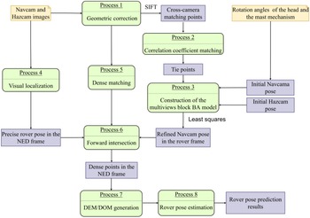
In this paper, we present the proposed visual pose prediction algorithm using the Navcam and Hazcam stereoimages. Figure 5 shows the workflow of the proposed algorithm.
Workflow of the proposed visual pose prediction algorithm.

After geometric correction, the geometric distortion of the Navcam images and Hazcam images is deleted. Because the scale-invariant feature transform (SIFT) [Reference Lowe26] is the most invariant to scale, rotation and viewpoint changes, SIFT is used to match the left images from Navcam and Hazcam, and the cross-camera matching points are obtained. Based on those points, the correlation coefficient matching method is applied in the stereo matching procedure. Then, the tie points (e.g., four degrees) in the stereo image sequence from different cameras can be obtained. The initial Navcam pose can be obtained from the rotation angles of the head and the mast mechanism. Next, an image network based on the multiviews block BA model with the initial Navcam/Hazcam pose and the tie points is established. The ordinary least squares solution is used, and the following parameters can be obtained and are considered to be known: the refined Navcam pose in
 $F_{\textit{Rover}}$
and the error of the camera pose. At the same time, a precise visual localization method in our previous work [Reference Ma, Liu, Sima, Wen, Peng and Jia1] is used to obtain a precise rover pose in
 $F_{NED}$
. Finally, dense matching [Reference Geiger, Roser and Urtasun27], forward intersection, DEM/DOM generation and rover pose estimation are used to obtain the rover pose prediction results in
 $F_{NED}$
.
Geometric constructions formed by the tie points between the cross-camera images are the basis for the Navcam pose estimation solution.
4.2. Refined Navcam pose by using multisensor images
4.1.1. The basic imaging model of the multiview block BA for the stereo Navcam/Hazcam system
To clarify the theory of the multiviews block BA, the collinearity equation is used [Reference Ma, Liu, Sima, Wen, Peng and Jia1] as follows:
 \begin{align}\begin{cases} x_{a}+{\unicode[Times]{x03B4}} x+x_{0}=-f\dfrac{a_{1}\left(X_{A}-X_{S}\right)+b_{1}\left(Y_{A}-Y_{S}\right)+c_{1}\left(Z_{A}-Z_{S}\right)}{a_{3}\left(X_{A}-X_{S}\right)+b_{3}\left(Y_{A}-Y_{S}\right)+c_{3}\left(Z_{A}-Z_{S}\right)}\\[12pt] y_{a}+{\unicode[Times]{x03B4}} y+y_{0}=-f\dfrac{a_{2}\left(X_{A}-X_{S}\right)+b_{2}\left(Y_{A}-Y_{S}\right)+c_{2}\left(Z_{A}-Z_{S}\right)}{a_{3}\left(X_{A}-X_{S}\right)+b_{3}\left(Y_{A}-Y_{S}\right)+c_{3}\left(Z_{A}-Z_{S}\right)} \end{cases} \end{align}
where
 $\left(f,x_{0}, y_{0}\right)$
denotes the principal distance and principle point;
 $(X_{A} Y_{A} Z_{A})$
denotes the 3D coordinates of tie point
 $A$
in
 $F_{\textit{Rover}}$
;
 $\left(x_{a} y_{a}\right)$
denotes the 2D coordinates of the corresponding image point
 $a$
;
 $\left(X_{S},Y_{S},Z_{S},\varphi _{S},\omega _{S},k_{S}\right)$
denotes the exterior orientation parameters (EOPs) of the Navcam/Hazcam in
 $F_{\textit{Rover}}$
,
 ${_{Rover}^{l}}{r}{}=(X_{S} Y_{S} Z_{S})$
;
 ${R}_{l}^{\textit{Rover}}=\left[\begin{array}{c@{\quad}c@{\quad}c} a_{1} & a_{2} & a_{3}\\ b_{1} & b_{2} & b_{3}\\ c_{1} & c_{2} & c_{3} \end{array}\right]=\left[\begin{array}{c@{\quad}c@{\quad}c} \cos \varphi _{S} & 0 & -\sin \varphi _{S}\\ 0 & 1 & 0\\ \sin \varphi _{S} & 0 & \cos \varphi _{S} \end{array}\right]\left[\begin{array}{c@{\quad}c@{\quad}c} 1 & 0 & 0\\ 0 & \cos \omega _{S} & -\sin \omega _{S}\\ 0 & \sin \omega _{S} & \cos \omega _{S} \end{array}\right]\left[\begin{array}{c@{\quad}c@{\quad}c} \cos k_{S} & -\sin k_{S} & 0\\ \sin k_{S} & \cos k_{S} & 0\\ 0 & 0 & 1 \end{array}\right]$
;
 $\left({\unicode[Times]{x03B4}} x{\unicode[Times]{x03B4}} y\right)$
represents the lens distortion of each image point.
4.1.2. The EOPs of the Navcam/Hazcam
When the multiview block BA is applied in the image network, the unknowns include
 $\left(X_{S},Y_{S},Z_{S},\varphi _{S},\omega _{S},k_{S},X_{A}, Y_{A}, Z_{A}\right)$
. Given appropriate initial values of the unknowns, the BA will converge, and the optimal EOPs of the Navcam will be calculated.
The telemetry data in the CE-4 mission include the rotation angles of the head and the mast mechanism. In that case, the rotation matrix
 ${R}_{nav\_ l}^{\textit{Rover}}$
and the vector
 ${_{Rover}^{nav\_ l}}{r}{}$
can be obtained by using the geometric relationship between
 $F_{\textit{Navcam}}$
and
 $F_{\textit{Rover}}$
, as shown in Formulas (5a) and (5b).
 \begin{equation}{R}_{nav\_ l}^{\textit{Rover}}={R}_{e}^{\textit{Rover}}R_{\textit{expand}}{R}_{Y}^{e}R_{yaw}{R}_{P}^{Y}R_{\textit{pitch}}{R}_{C}^{P}{R}_{nav\_ l}^{C}\end{equation}
 \begin{equation}{_{Rover}^{nav\_ l}}{r}{}={R}_{e}^{\textit{Rover}}R_{\textit{expand}}\left({R}_{Y}^{e}R_{yaw}\left({R}_{P}^{Y}R_{\textit{pitch}}\left({R}_{C}^{P}{T}_{l}^{C}+{T}_{C}^{P}\right)+{T}_{P}^{Y}\right)+{T}_{Y}^{e}\right)+{T}_{e}^{\textit{Rover}}\end{equation}
where
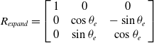 $R_{\textit{expand}}=\left[\begin{array}{c@{\quad}c@{\quad}c} 1 & 0 & 0\\ 0 & \cos \theta _{e} & -\sin \theta _{e}\\ 0 & \sin \theta _{e} & \cos \theta _{e} \end{array}\right]$
denotes the rotation matrix between
 $F_{\textit{Rover}}$
and
 $F_{e}$
;
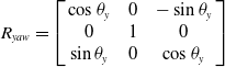 $R_{yaw}=\left[\begin{array}{c@{\quad}c@{\quad}c} \cos \theta _{y} & 0 & -\sin \theta _{y}\\ 0 & 1 & 0\\ \sin \theta _{y} & 0 & \cos \theta _{y} \end{array}\right]$
denotes the rotation matrix between
 $F_{e}$
and
 $F_{y}$
;
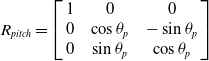 $R_{\textit{pitch}}=\left[\begin{array}{c@{\quad}c@{\quad}c} 1 & 0 & 0\\ 0 & \cos \theta _{p} & -\sin \theta _{p}\\ 0 & \sin \theta _{p} & \cos \theta _{p} \end{array}\right]$
denotes the rotation matrix between
 $F_{y}$
and
 $F_{p}$
;
 ${R}_{e}^{\textit{Rover}}$
,
 ${R}_{Y}^{e}$
,
 ${R}_{P}^{Y}$
,
 ${R}_{C}^{P}$
, and
 ${R}_{nav\_ l}^{C}$
denote the known rotation matrix, and the corresponding angle measurement accuracy is
 $1.0\mathrm{''}$
; and
 ${T}_{l}^{C}$
,
 ${T}_{C}^{P}$
,
 ${T}_{P}^{Y}$
,
 ${T}_{Y}^{e}$
and
 ${T}_{e}^{\textit{Rover}}$
denote the known transformation vector.
The Hazcam pose in
 $F_{\textit{Rover}}$
, including the rotation matrix
 ${R}_{haz\_ l}^{\textit{Rover}}$
and the vector
 ${_{Rover}^{haz\_ l}}{r}{}$
, will be presented as:
 \begin{equation}{_{Rover}^{haz\_ l}}{r}{}={R}_{C}^{\textit{Rover}}{T}_{haz\_ l}^{C}+{T}_{C}^{\textit{Rover}},\end{equation}
 \begin{equation}{R}_{haz\_ l}^{\textit{Rover}}={R}_{C}^{\textit{Rover}}{R}_{haz\_ l}^{C},\end{equation}
where
 ${T}_{haz\_ l}^{C}$
and
 ${T}_{C}^{\textit{Rover}}$
denote the transformation vector among the Hazcam frame, the cube mirror frame and
 $F_{\textit{Rover}}$
, respectively;
 ${R}_{C}^{\textit{Rover}}$
denotes the rotation matrix between the latter two frames, where the angle measurement error is
 $1.0\mathrm{''}$
, and
 ${R}_{haz\_ l}^{C}$
denotes the rotation matrix between the Hazcam frame and the cube mirror frame.
4.1.3 Least squares solution of the multiview block BA model
To improve the robustness of the proposed method, the geometry constraint condition of the stereo Navcams and Hazcams should be adopted in the multiview block BA. It is noted that the relative pose of the stereo Navcams/Hazcams is obtained in advance during the camera calibration procedure.
Using Taylor’s formula, the linearization equation of Formula (4) can be derived in Gauss–Markov mode:
 \begin{align}\begin{cases} v_{{x_{a}}}-\dfrac{\partial x_{a}}{\partial X}V_{X}-\dfrac{\partial x_{a}}{\partial Y}V_{Y}-\dfrac{\partial x_{a}}{\partial Z}V_{Z}={x}_{a}^{0}-x_{a}+\dfrac{\partial x_{a}}{\partial X_{S}}{\unicode[Times]{x03B4}} X_{S}+\dfrac{\partial x_{a}}{\partial Y_{S}}{\unicode[Times]{x03B4}} Y_{S}+\dfrac{\partial x_{a}}{\partial Z_{S}}{\unicode[Times]{x03B4}} Z_{S}+\dfrac{\partial x_{a}}{\partial \varphi _{S}}{\unicode[Times]{x03B4}} \varphi _{S}+\dfrac{\partial x_{a}}{\partial \omega _{S}}{\unicode[Times]{x03B4}} \omega _{S}+\dfrac{\partial x_{a}}{\partial k_{S}}{\unicode[Times]{x03B4}} k_{S}\\[12pt] v_{{y_{a}}}-\dfrac{\partial y_{a}}{\partial X}V_{X}-\dfrac{\partial y_{a}}{\partial Y}V_{Y}-\dfrac{\partial y_{a}}{\partial Z}V_{Z}={y}_{a}^{0}-y_{a}+\dfrac{\partial y_{a}}{\partial X_{S}}{\unicode[Times]{x03B4}} X_{S}+\dfrac{\partial y_{a}}{\partial Y_{S}}{\unicode[Times]{x03B4}} Y_{S}+\dfrac{\partial y_{a}}{\partial Z_{S}}{\unicode[Times]{x03B4}} Z_{S}+\dfrac{\partial y_{a}}{\partial \varphi _{S}}{\unicode[Times]{x03B4}} \varphi _{S}+\dfrac{\partial y_{a}}{\partial \omega _{S}}{\unicode[Times]{x03B4}} \omega _{S}+\dfrac{\partial y_{a}}{\partial k_{S}}{\unicode[Times]{x03B4}} k_{S} \end{cases}\end{align}
where
 ${x}_{a}^{0},{y}_{a}^{0}$
denotes the calculated values of the 2D coordinates of the image points, which can be obtained by using Formula (4);
 $\dfrac{\partial .}{\partial .}$
is the derivative, and
 ${\unicode[Times]{x03B4}}$
denotes the corrections of the EOPs;
 $v_{{x_{a}}},v_{{y_{a}}}$
represent the correction of the 2D image points in
 $F_{xy}$
;
 $V_{X},V_{Y},V_{Z}$
represent the correction of the 3D coordinates of the tie point.
Then, Formula (7) can be described as a generalized model:
 \begin{equation}V_{x}=a_{x}t+B_{x}M-L_{x}\end{equation}
where
 $V_{x}=\left[v_{{x_{a}}} v_{{y_{a}}}\right]^{\mathrm{T}}$
,
 $t=\left({\unicode[Times]{x03B4}} X_{S},{\unicode[Times]{x03B4}} Y_{S},{\unicode[Times]{x03B4}} Z_{S},{\unicode[Times]{x03B4}} \varphi _{S},{\unicode[Times]{x03B4}} \omega _{S},{\unicode[Times]{x03B4}} k_{S}\right)^{\mathrm{T}}$
,
 $M=\left({\unicode[Times]{x03B4}} X,{\unicode[Times]{x03B4}} Y,{\unicode[Times]{x03B4}} Z\right)^{\mathrm{T}}$
, and
 $L_{x}=\left[{x_{a}-x}_{a}^{0}{y_{a}-y}_{a}^{0}\right]^{\mathrm{T}}$
;
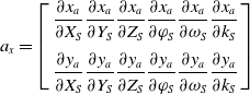 $a_{x}=\left[\begin{array}{c} \dfrac{\partial x_{a}}{\partial X_{S}}\dfrac{\partial x_{a}}{\partial Y_{S}}\dfrac{\partial x_{a}}{\partial Z_{S}}\dfrac{\partial x_{a}}{\partial \varphi _{S}}\dfrac{\partial x_{a}}{\partial \omega _{S}}\dfrac{\partial x_{a}}{\partial k_{S}}\\[12pt] \dfrac{\partial y_{a}}{\partial X_{S}}\dfrac{\partial y_{a}}{\partial Y_{S}}\dfrac{\partial y_{a}}{\partial Z_{S}}\dfrac{\partial y_{a}}{\partial \varphi _{S}}\dfrac{\partial y_{a}}{\partial \omega _{S}}\dfrac{\partial y_{a}}{\partial k_{S}} \end{array}\right]$
,
 $B_{x}=\left[\begin{array}{c} \dfrac{\partial x_{a}}{\partial X}\dfrac{\partial x_{a}}{\partial Y}\dfrac{\partial x_{a}}{\partial Z}\\[12pt] \dfrac{\partial y_{a}}{\partial X}\dfrac{\partial y_{a}}{\partial Y}\dfrac{\partial y_{a}}{\partial Z} \end{array}\right]$
.
The stochastic model for Formula (8) is:
 \begin{equation}V_{x}\sim N\left(\begin{array}{cc} 0, & {\sigma }_{0}^{2} \end{array}{P_{x}}^{-1}\right),\end{equation}
where
 $P_{x}$
is the corresponding weight matrix and
 $\sigma _{0}$
is the prior variance component.
The EOPs of the Navcams and Hazcams can be acquired from Formulas (5)-(6) before the BA is applied. Hence, the EOPs should be viewed as pseudo-observations [Reference Ma, Liu, Sima, Wen, Peng and Jia1, Reference Yuan28] for the multiview block BA:
 \begin{align} \begin{cases} \begin{array}{c} v_{{X_{S}}}={\unicode[Times]{x03B4}} X_{S}\\ v_{{Y_{S}}}={\unicode[Times]{x03B4}} Y_{S} \end{array}\\ \begin{array}{c} v_{{Z_{S}}}={\unicode[Times]{x03B4}} Z_{S}\\ v_{{\varphi _{S}}}={\unicode[Times]{x03B4}} \varphi _{S} \end{array}\\ \begin{array}{c} v_{{\omega _{S}}}={\unicode[Times]{x03B4}} \omega _{S}\\ v_{{k_{S}}}={\unicode[Times]{x03B4}} k_{S} \end{array} \end{cases}\!\!\!\!\!\!\!.\end{align}
Formula (10) can be viewed as:
 \begin{equation}V_{po}=It.\end{equation}
The stochastic model for Formula (11) is:
 \begin{equation}V_{po}\sim N\left(\begin{array}{cc} 0, & {\sigma }_{0}^{2} \end{array}{P_{po}}^{-1}\right),\end{equation}
where
 $P_{po}$
is the corresponding weight matrix,
 $V_{po}=\left[v_{{X_{S}}} v_{{Y_{S}}} v_{{Z_{S}}} v_{{\varphi _{S}}} v_{{\omega _{S}}} v_{{k_{S}}} \right]^{\mathrm{T}}$
.
In this case, the number of observation values will increase, which further improves the estimation precision of the EOPs in the multiview block BA.
When a least squares solution is applied, the Lagrange target function can be written as
 $\varnothing \left(\epsilon,\rho \right)={V_{x}}^{\mathrm{T}}P_{x}V_{x}+{V_{po}}^{\mathrm{T}}P_{po}V_{po}+2\rho ^{\mathrm{T}}\left(Gt+W\right)$
. In which
 $\rho$
denotes the vector of the unknown Lagrange multipliers. When the first-order condition equations
 $\frac{\partial \varnothing }{\partial \in },\frac{\partial \varnothing }{\partial \rho }$
are set as zero, the unknowns can be viewed as:
 \begin{equation}\epsilon =u+\left(\gamma ^{\mathrm{T}}P_{x}\gamma +{I}_{0}^{\mathrm{T}}P_{po}I_{0}\right)^{-1}{G}_{0}^{\mathrm{T}}\left(G_{0}\left(\gamma ^{\mathrm{T}}P_{x}\gamma +{I}_{0}^{\mathrm{T}}P_{po}I_{0}\right)^{-1}{G}_{0}^{\mathrm{T}}\right)^{-1}\left(-W-G_{0}\mu \right),\end{equation}
where
 $\mu =\left(\gamma ^{\mathrm{T}}P_{x}\gamma +{I}_{0}^{\mathrm{T}}P_{po}I_{0}\right)^{-1}\gamma ^{\mathrm{T}}P_{x}L_{x}$
;
 $\gamma =\left[a_{x} B_{x}\right]$
,
 $G_{0}=\left[G\;\;\;0\;\;\;0\;\;\;0\right]$
,
 $\epsilon =[t M]$
;
In a single image,
 $I_{0}=\left[\begin{array}{cc} I_{6\times 6} & 0\\ 0 & 0_{3\times 3} \end{array}\right]$
;
where
 $G=\left[{G}_{i}^{l}\;\;\;{ G}_{i}^{r}\;\;\; {G}_{j}^{l}\;\;\;{ G}_{j}^{r}\right]$
denotes the coefficient matrices, which are partial derivatives for each variable. The subscripts
 $i,\text{and }j$
represent the Navcams and Hazcams, respectively, and the superscripts
 $l,\text{and }r$
represents the left camera and the right camera, respectively;
 $W=-F^{0}-E$
, where
 $F$
and
 $E$
represent constant terms, and
 $F^{0}$
represents the constant vector when the initial extrinsic parameters are all set to zero, which can be seen in ref. [Reference Ma, Liu, Sima, Wen, Peng and Jia1].
It is noted that
 $P_{po}={\sigma }_{0}^{2}/{\sigma }_{po}^{2}I$
, and
 $\sigma _{po}$
represents the precision of the pseudo-observations. In the case of the Navcams, the pseudo-observations are primarily influenced by the errors in the rotation angles of the head and the mast mechanism. Thus,
 $\sigma _{po}$
can be set to
 $\sigma _{r}$
, where
 $\sigma _{r}$
denotes the precision (0.3
 $^{\circ}$
) of the rotation angles. Here,
 $\sigma _{0}=\sigma _{p}$
denotes the precision value (0.2 pixels) of the matching image point. In the case of the Hazcams, the pseudo-observations are primarily influenced by the estimated precision of the camera pose. Here,
 $\sigma _{po}$
is set to
 $\sigma _{m}$
, where
 $\sigma _{m}$
denotes the calculated precision (
 $\sigma _{{\varphi _{S}}},\sigma _{{\omega _{S}}},\sigma _{{k_{S}}}$
= 0.1
 $^{\circ}$
, 0.06
 $^{\circ}$
, 0.06
 $^{\circ})$
of the Hazcam pose in the camera calibration procedure.
Formulas (8) and (11) can be solved based on the least squares solution, and the root mean square error (RMSE)
 $\sigma _{0}$
can be expressed as:
 \begin{equation}\sigma _{0}=\sqrt{\left({V}_{x}^{\mathrm{T}}P_{x}V_{x}+{V}_{po}^{\mathrm{T}}P_{po}V_{po}\right)/t_{0}},\end{equation}
where
 $t_{0}$
is the redundancy. The RMSE of the unknowns is given as:
 \begin{equation}\sigma _{tt}=\sigma _{0}\sqrt{\left({\unicode[Times]{x03B3}} ^{\mathrm{T}}P_{x}{\unicode[Times]{x03B3}} +{I}_{0}^{\mathrm{T}}P_{1}I_{0}\right)^{-1}},\end{equation}
where
 $\sigma _{tt}=(\sigma _{{X_{S}}},\sigma _{{Y_{S}}},\sigma _{{Z_{S}}},\sigma _{{\varphi _{S}}},\sigma _{{\omega _{S}}},\sigma _{{k_{S}}})$
,
 $P_{1}=\left[\begin{array}{cc} P_{po} & 0\\ 0 & I_{3\times 3} \end{array}\right]$
.
4.3. Rover pose prediction based on the topographic product
The topographic products (DEM/DOM) in the current position are all generated with the stereo Navcam images in the rover’s telemetry operating system on the ground (earth). As the lunar night approaches, searching for the rover pose in the next station must be studied based on those topographic products. To simplify the analysis, the rover pose prediction is formulated as a rigid body contact problem for a given location of the rover’s center over the DEM and a given attitude angle
 $\gamma _{y}$
. First, the plane positions of the front and back wheels are calculated by using the given location of the rover’s center
 $O$
and the actual geometrical sizes. Second, the nearest points in the DEM are obtained based on the above plane positions, and the elevation of the contact points between the wheels (the front wheels
 $A,B$
and the back wheels
 $C,D$
) and ground can be interpolated by the kriging method with some nearby points. Third, the other attitude angles (
 $\gamma _{p},\gamma _{r}$
) of the rover will be approximately calculated through the 3D coordinates
 $XYZ$
of those contact points, which are as follows:
 \begin{align} \begin{cases} \gamma _{p}=-\text{atan}\left(\left(Z_{AB}-Z_{CD}\right)/\sqrt{\left(X_{AB}-X_{CD}\right)^{2}+\left(Y_{AB}-Y_{CD}\right)^{2}}\right)\\[5pt] \gamma _{r}=\text{atan}\left(\left(Z_{BD}-Z_{AC}\right)/\sqrt{\left(X_{AC}-X_{BD}\right)^{2}+\left(Y_{AC}-Y_{BD}\right)^{2}}\right), \end{cases}\end{align}
where
 $\text{atan}$
denotes the arctangent function,
 $\tau _{AB}=\left(\tau _{A}+\tau _{B}\right)/2$
,
 $\tau _{CD}=\left(\tau _{C}+\tau _{D}\right)/2$
,
 $\tau _{AC}=\left(\tau _{A}+\tau _{C}\right)/2$
,
 $\tau _{BD}=\left(\tau _{B}+\tau _{D}\right)/2$
, and
 $\tau \in \left\{X Y Z\right\}$
.
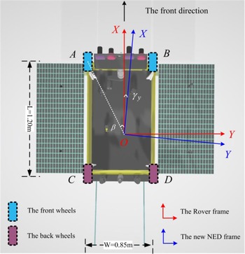
As shown in Fig. 6,
 $\beta =35.3$
degrees, the blue lines denote the new NED frame
 ${F}_{NED}^{'}$
, where the origin is the origin
 $O$
of
 $F_{\textit{Rover}}$
. Given a yaw angle
 $\gamma _{y}$
and the plane location
 $X_{O},Y_{O}$
of the rover, the 2D coordinates (
 $X Y$
) of the centers of the wheels
 $A,B,C,D$
can be obtained in
 ${F}_{NED}^{'}$
.
Rover pose estimation concept (top view).

When the rover’s attitude angles (
 $\gamma _{p},\gamma _{r}$
) meet the set requirement, the rover must stop working and be ready to enter the sleeping mode in the corresponding given location.
The proposed algorithm is applied in the full DEM image search. The column and the row of each pixel in the DEM present a plane location of the rover. Thus, the above procedure should be repeated. In practice, the parallel processing technique of multithreading is applied to search for the potential location for the rover’s sleeping mode in the DEM. In the processing of the rover pose prediction based on the DEM, there are usually difficulties in that many potential results are obtained. All of the associated factors (the distance, the terrain trafficability, energy, and so on) shall be considered prior to selecting the most suitable pose (location and attitude angles) for the rover from those potential results.
5. Experimental results
5.1. Experimental results of visual pose estimation for the Yutu-2 rover in the indoor field
5.1.1. Terrain reconstruction
In the terrain reconstruction procedure, the proposed method (referred to as proposed) is compared with the classical terrain reconstruction method (referred to as Classical-TR) [Reference Wang, Wan, Gou, M.Peng, Di, Li, Yu, Wang and Cheng4, Reference Li, Squyres, Arvidson, Archinal, Bell, Cheng and Golombek6–Reference Liu, Di, Peng, Wan, Liu and Li8], the BA method based on the ordinary least squares (referred to as BA + Geometry) [Reference Ma, Liu, Sima, Wen, Peng and Jia1], the CAHVOR method [Reference Di and Li17] and the integrated self-calibration method [Reference Zhang, Liu, Ma, Qi, Ma and Yang19] (referred to as ISC). In Classical-TR, the Navcam pose is directly obtained by using the coordinate system transformation framework [Reference Ma, Liu, Sima, Wen, Peng and Jia1]. In BA + Geometry, Formula (8) is invoked, while the matrix
 $I$
is set as a zero matrix. Formulas (5) and (6) are only used to obtain the initial Navcam/Hazcam pose. In CAHVOR, the transformation from the object space to the image plane is obtained, which is almost the same as Classical-TR. In ISC, the measured rotation angles of the mast mechanism are viewed as the actual values and are used as inputs. In those methods, the rover localization results [Reference Ma, Liu, Sima, Wen, Peng and Jia1] and the dense matching process [Reference Geiger, Roser and Urtasun27] are the same, which are both self-programmed in C++.
Before the CE-4 mission began, the proposed algorithm was tested with a model rover, which has the same size and functions as Yutu-2, in a simulated indoor field with artificial craters and rocks. The rover pose, the 3D coordinates of the feature points in
 $F_{\textit{Rover}}$
and the cube mirror frame
 $F_{C}$
were measured, which can be viewed as the true data (the angular precision was
 $2.0\mathrm{''}$
and coordinate measurement precision was 0.12 mm). It is noted that
 $F_{C}$
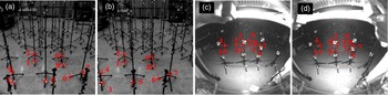
was mounted on top of the left Navcam. Theoretically, the tie points should be evenly distributed in the overlapping areas between the Navcam/Hazcam FOV. However, the 3D measurement errors of the stereo Navcam/Hazcam images are another factor that affects the Navcam pose estimation precision. In other words, the tie points should be selected from the lower part of the above overlapping areas. The tie points were extracted using the Hough line detection method and the manual matching process, whose precision was almost 0.5 pixels. Figure 7 shows the distribution of the selected tie points, and the rotation angles (
 $\theta _{e},\theta _{y},\theta _{p}$
) at the current station are 0.0 degrees, 0.09 degrees and −29.93 degrees. The distance between the various tie points and the front wheel ranges from 1.3 to 2.2 m.
(a), (b) Distributions of the nine selected tie points of stereoimages in the test field. (c) The stereo Navcam image; (d) the stereo Hazcam image. The red crosses indicate the locations of the tie points, and the red numbers indicate the number of each tie point.

To test the relationships between the left Navcam pose estimation based on different methods and the number of tie points, the following four cases were considered:
Case 0. nine tie points (“1, 2, 3, 4, 5, 6, 7, 8, 9”);
Case 1. Eight tie points (“1, 2, 3, 4, 5, 7, 8, 9”);
Case 2. six tie points (“1, 3, 4, 5, 7, 8”);
Case 3. Five tie points (“1, 2, 4, 8,9”).
In those cases of the proposed algorithm, the number of iterations was set to 6, and the results are presented in Table I.
The left Navcam pose estimated results using different methods for four different cases.

The test environment was an Intel(R) Core(TM) i5@2.50 GHz, 2 GB windows system.
The column “
 $\sigma _{0}$
/pixels” of Table I, which indicates the RMSE of the reprojections and the left Navcam pose [Reference Qing, Chuang, Bo, Shuo, Lei and Song9], is different in the four cases. In column “
 ${\unicode[Times]{x03B4}}$
” of Table I, the symbol
 ${\unicode[Times]{x03B4}} =\sqrt{\left({\overline{X}_{S}}-{\hat{X}_{S}}\right)^{2}+\left({\overline{Y}_{S}}-{\hat{Y}_{S}}\right)^{2}+\left({\overline{Z}_{S}}-{\hat{Z}_{S}}\right)^{2}}$
denotes the absolute error value of the left Navcam’s position estimation. The symbols
 $\left(\hat{X}_{S},\hat{Y}_{S},\hat{Z}_{S},\hat{\varphi }_{S},\hat{\omega }_{S},\hat{k}_{S}\right)$
represent the left Navcam pose estimation based on the above five methods. The symbols
 $\left(\overline{X}_{S},\overline{Y}_{S},\overline{Z}_{S},\overline{\varphi }_{S},\overline{\omega }_{S},\overline{k}_{S}\right)$
correspond to the true data of the left Navcam pose, which are −139.8, 1252.5, −550.7 mm, 0.003746, −0.516179, and 0.001085 rad, respectively. It is noted that the left Navcam pose
 $(X_{S},Y_{S},Z_{S},\varphi _{S},\omega _{S},k_{S})$
in
 $F_{\textit{Rover}}$
can be acquired by using the SCBA method with 59 control points. Here,
 $\sigma _{0}$
in the SCBA method was 0.18 pixels, while
 $\sigma _{tt}$
of the estimated camera pose was 0.3, 0.6, 1.3 mm, 0.001178, 0.000910 and 0.000539 rad. Hence, the camera pose estimation was viewed as the true data, which was denoted by
 $\left(\overline{X}_{S},\overline{Y}_{S},\overline{Z}_{S},\overline{\varphi }_{S},\overline{\omega }_{S},\overline{k}_{S}\right)$
. The symbols
 ${\unicode[Times]{x03B4}} \varphi =\left| \hat{\varphi }_{S}-\overline{\varphi }_{S}\right|,{\unicode[Times]{x03B4}} \omega =\left| \hat{\omega }_{S}-\overline{\omega }_{S}\right|,{\unicode[Times]{x03B4}} k=\left| \hat{k}_{S}-\overline{k}_{S}\right|$
denote the absolute error value of the left Navcam’s altitude angles. The results in Table I indicate the following:
-
1. The Navcam’s position parameters by using the proposed algorithm were much closer to the true data than those of BA + Geometry, CAHVOR, Classical-TR and ISC. In CAHVOR, Classical-TR and ISC, the parameter
${\unicode[Times]{x03B4}}$
was 6.7 mm. In case 0, case 1, case 2 and case 3 of the proposed algorithm, the parameters
${\unicode[Times]{x03B4}}$
values were 63.08%, 68.80%, 52.87% and 48.47% of those obtained by CAHVOR, respectively. In cases 0-3 of BA + Geometry, the parameters
${\unicode[Times]{x03B4}}$
values were 62.69%, 65.54%, 51.38% and 43.48% of those obtained by CAHVOR, respectively. For example, the absolute errors of the left Navcam’s altitude angles
$({\unicode[Times]{x03B4}} \varphi,{\unicode[Times]{x03B4}} \omega,{\unicode[Times]{x03B4}} k)$
in case 1 were 0.007195 0.002868 and 0.000401 rad, respectively, while the corresponding errors in Classical-TR were 0.009993 0.005105 and 0.024229 rad. Thus, the proposed algorithm was able to correct the Navcam pose in case 1. -
2. To improve the Navcam pose estimation precision, the tie points’ distribution should be uniform and more concentrated in the lower part of the image’s overlapping areas in the proposed algorithm and BA + Geometry. Here, the
${\unicode[Times]{x03B4}},{\unicode[Times]{x03B4}} \varphi,{\unicode[Times]{x03B4}} \omega,{\unicode[Times]{x03B4}} k$
values in case 1 were higher than those of case 0, case 2 and case 3. Through the thirteenth column of Table I,
$\sigma _{0}$
is 0.51 pixels, 0.50 pixels, 0.68 pixels and 0.77 pixels in case 0, case 1, case 2 and case 3 of the proposed algorithm, respectively. In general, the greater the number of tie points and the more concentrated the tie points’ distribution, the higher the Navcam pose estimation precision in case 1, case 2 and case 3. However, this phenomenon did not occur in case 0. In case 0, the forward intersection method was used to calculate the 3D coordinates of the nine tie points with the Navcam stereo pair and Hazcam stereo pair, and the reconstruction precision result is listed in Table II.


The reconstruction precision of all selected tie points.

In Table II, the symbols
 $\sigma _{X},\sigma _{Y},\sigma _{Z}$
represent the RMSE of the tie points’ coordinates, where the symbol
 $\sigma _{XYZ}$
equals
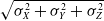 $\sqrt{{\sigma }_{X}^{2}+{\sigma }_{Y}^{2}+{\sigma }_{Z}^{2}}$
. The
 $\sigma _{XYZ}$
value of tie point “6” is 26.5 mm, while
 $\sigma _{XYZ}$
values of the other eight tie points range from 12.7 to 18.4 mm. Because tie point “6” was selected manually, the corresponding image points have a lower extraction precision. Hence, a low-precision extracted image point will result in a low reconstruction precision. In case 1, all of the tie points except for “6” were used to estimate the left Navcam pose, and the estimated camera pose was much closer to the true data than in case 0, case 2 and case 3. The other tie points (“1, 2, 3, 4, 5, 7, 8, 9”) had similar image extraction precisions, which further indicates that more tie points can promote the visual reconstruction precision.
From a theoretical standpoint, the reconstruction precisions of the feature points determined by using the Navcam stereo pair were slightly higher than those determined by using the Hazcam stereo pair within a certain range. However, due to the measurement errors of the rotation angles of the head and the mast mechanism, the reconstruction precision of the feature points in the Navcam stereo pair decreased. The mean absolute error of the feature points by using the stereo Navcam images and the coordinate system transformation framework decreased to 36.2 mm in the range 0.8–2.2 m. However, the mean absolute error of the feature points determined by using the Hazcam images pair in
 $F_{\textit{Rover}}$
was 4.6 mm in the range 0.8–2.2 m. When the left Navcam pose in
 $F_{\textit{Rover}}$
was refined with the tie points by using the proposed algorithm, then the corresponding reconstruction precision of those tie points and other check points was increased.
The reconstruction precisions of the check points determined by using the proposed algorithm, BA + Geometry, CAHVOR, Classical-TR and ISC are shown in Fig. 8. The 3D coordinates of the check points in the left Navcam frame
 $F_{\textit{Navcam}}$
were first calculated by the forward intersection method with the stereo Navcam pair. Second, those check points were translated to frame
 $F_{\textit{Rover}}$
with the corresponding estimated camera pose by the above five methods. Third, the absolute errors of those check points were calculated with the measured 3D coordinates (
 $X,Y,Z$
).
Precision of the 3D coordinates of the checkpoints.

In Fig. 8, the red star points, cyan points, green points, yellow points and black points represent the absolute errors of the 3D coordinates in the proposed algorithm, BA + Geometry, CAHVOR, Classical-TR and ISC, respectively. Through statistical analysis, the mean absolute errors of the check points in the proposed algorithm, BA + Geometry, CAHVOR, Classical-TR and ISC were 10.4, 11.3, 19.3, 20.4 and 20.2 mm in the range
 $L$
from 2.0 to 6.1 m, respectively. Thus, the reconstruction precisions of the proposed algorithm were better than those of BA + Geometry, CAHVOR, Classical-TR and ISC. Meanwhile, the precisions of the 3D coordinates of the check points in CAHVOR, Classical-TR and ISC were almost the same.
It was noted that
 ${\unicode[Times]{x03B4}} \varphi,{\unicode[Times]{x03B4}} \omega,{\unicode[Times]{x03B4}} k$
in case 0, case 2 and case 3 of the proposed algorithm were higher than those of CAHVOR, Classical-TR and ISC, while the parameter
 ${\unicode[Times]{x03B4}}$
was lower. This shows that the stability of the attitude angles was lower than the position in the least squares solution of the proposed algorithm.
-
1. The proposed algorithm in case 0 took more time than it took in cases 1–3. To assess the calculating efficiency, the calculation times of cases 0–3 from the process of inputting the matching image points to the calculation of the Navcam pose are listed in the column “Times (ms)” of Table I.
To validate the terrain reconstruction precision in the overlapping area, 3D point cloud processing software (CloudCompare) was used. For more details, see the website https://www.danielgm.net/cc/. CloudCompare provides a set of basic tools for manually editing and rendering 3D point clouds and triangular meshes. It also offers various advanced processing algorithms, among which are methods for performing distance computations (cloud-cloud or cloud-mesh nearest neighbor distance). The mean value and the standard deviation (std. dev.) in a Gaussian model are two of the important indices used to judge point cloud registration. The proposed algorithm, Classical-TR, BA + Geometry and the Loop-closed BA method [Reference Ma, Peng, Jia and Liu2] were used to obtain the terrain information. Because the reconstruction precisions of the check points in CAHVOR, Classical-TR and ISC are almost the same, CAHVOR was chosen as the method that would be used for making comparisons. Taking Station A as an example, 8 pairs of stereo Navcam images and one pair of Hazcam images were obtained, and the rotation angles (
 $\theta _{e},\theta _{y},\theta _{p}$
) of the head and the mast mechanism at the current station were 0.066 degrees, –60∼+60 degrees and –23.998 degrees, respectively. In the Loop-closed BA, the control points on the model rover cannot be selected in the Navcam images, and a total of 158 matching points were extracted. There were 5 iterations. Using the Loop-closed block BA model based on the TLS solution,
 $\sigma _{0}$
is 1.5 pixels.
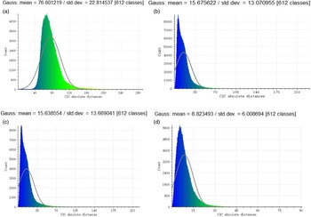
Using a Faro 3D laser scanner, we acquired the point cloud data of the real indoor field. The measured precision was approximately 1.2 mm. Hence, these point cloud data from the Faro 3D laser scanner were viewed as the true data. The terrain products from the above four methods can be compared with the point cloud data obtained by using CloudCompare software. Figure 9 shows the terrain reconstruction results that were obtained by using the above four methods.
Terrain reconstruction results at Station D. (a): Classical-TR; (b): BA + Geometry; (c): Loop-closed BA; (d): the proposed algorithm.

As shown in Fig. 9, the mean values in the proposed algorithm, Loop-closed BA, BA + Geometry and Classical-TR methods were 8.8, 15.6, 15.7 and 76.6 mm, respectively, while the std. dev. Values were 6.0, 13.6, 13.1 and 22.8, respectively. The results indicate that the proposed algorithm can improve the reconstruction precision with the stereo Navcam pair and the stereo Hazcam pair.
5.1.2. Visual pose prediction
The movement path of the model rover can be viewed in [Reference Ma, Liu, Sima, Wen, Peng and Jia1]. At Stations 1 to 6, seven or eight pairs (a backward pair was added) of Navcam stereoimages and one pair of Hazcam stereoimages were captured, which validated the robustness and performance of the developed software. At Stations 2 to 6, the measurement positions and attitude angles of the rover in
 $F_{\textit{control}}$
were measured, which can be viewed as the true data. At the same time, the visual pose estimation results for the rover were also given using the BA + pseudo method [Reference Ma, Liu, Sima, Wen, Peng and Jia1]. With the visual pose estimation of the rover as input, the topographic products were obtained through the terrain reconstruction procedure. Note that the rover pose and the topographic products (DEM/DOM) were all in
 $F_{\textit{control}}$
. In the analysis, given the measured yaw angle
 $\gamma _{y}$
and the plane location
 $(X_{O},Y_{O})$
of the rover, the pitch and roll angle of the rover was calculated by the proposed algorithm, which are denoted as (
 $\hat{\gamma }_{p},\hat{\gamma }_{r}$
). The measured angles (
 $\gamma _{p},\gamma _{r}$
) and the calculated angles (
 $\hat{\gamma }_{p},\hat{\gamma }_{r}$
) of the rover at five stations are given in Table III.
Measured angles and calculated angles of the rover at five stations.

In Table III,
 ${\unicode[Times]{x03B4}} \gamma _{p}=\gamma _{p}-\hat{\gamma }_{p}$
,
 ${\unicode[Times]{x03B4}} \gamma _{r}=\gamma _{r}-\hat{\gamma }_{r}$
. The estimated pitch and roll angles of the rover at Stations 2 to 6 were obtained using the input data from Stations 1 to 5, respectively. From the ninth and tenth columns of Table III, the average values of
 ${\unicode[Times]{x03B4}} \gamma _{p},{\unicode[Times]{x03B4}} \gamma _{r}$
were −0.19 degrees and 0.29 degrees, respectively. The results indicate that the predicted values of
 $\gamma _{p}$
were closer to the true data than
 $\gamma _{r}$
, while both the pitch and roll angle met the set requirements for entering the sleeping mode of the rover. In practice, the angles
 $\gamma _{y},\gamma _{p},\gamma _{r}$
of the Yutu-2 rover must be set as 161 degrees to 169 degrees, −4 degrees to 14 degrees and −2 degrees to 1.5 degrees, respectively. The specific numerical ranges of the rover pose directly originate from the ground thermal testing of Yutu-2.
5.2. Applications of visual pose estimation for the Yutu-2 rover of the CE-4 mission
On 30 March 2019, the service design goal (three months) of Yutu-2 was reached. During the operation cycle, Yutu-2 had gone through the lunar night three times, and the locations for entering the sleeping mode of the rover were Stations S1, LE00210 and LE00309. It is noted that the attitude angles of the rover were measured by the Sun sensor, whose angular precision is 1.0 degrees (3
 $\sigma$
). To predict the rover pose at those stations, the Navcam images, Hazcam images and other telemetry data at Stations D, LE00209 and LE00308 were, respectively.
5.2.1. Terrain reconstruction
To validate the terrain reconstruction procedure based on the proposed algorithm, Classical-TR, BA + Geometry and Loop-closed BA, the Navcam/Hazcam images and other telemetry data at Stations D, LE00306 and LE00308 were used. By comparing the mean values and the standard deviations of the above terrain descriptions from the above-mentioned four methods and the terrain description based on the stereo Hazcam images, we were able to establish whether the above algorithms worked and precisely how well.
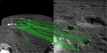
Taking Station D as an example, 16 pairs of stereo Navcam images and one pair of Hazcam images were obtained. Figure 10 shows the initial image matching results between the different images by using SIFT.
Initial image matching results at Station D: Left Hazcam image and the ninth left Navcam image.

In Fig. 10, the number of initial matching points was 45, and the distance to the rover ranged from 0.9 to 2.3 m. When the tie point extraction method presented in this paper was used, the number of good tie points was 26. The white rectangle in Fig. 10 represents the overlapping image area between the left Hazcam image and the ninth left Navcam image. It was noted that the rotation angles (
 ${\unicode[Times]{x03B8}} _{\mathrm{e}},{\unicode[Times]{x03B8}} _{\mathrm{y}},{\unicode[Times]{x03B8}} _{\mathrm{p}}$
) in the case of the ninth left Navcam pose were 0.109 degrees, 10.108 degrees and −29.929 degrees, respectively.
To validate the terrain reconstruction precision in the overlapping area, the proposed algorithm, Classical-TR, BA + Geometry and the Loop-closed BA method were used to obtain the terrain description. Figure 11 shows the terrain reconstruction results obtained by using the above-mentioned methods. In “Loop-closed BA” [Reference Ma, Peng, Jia and Liu2], 19 control points on the structure of the model rover were selected, and a total of 235 matching points were extracted, of which 216 had four-degree overlapping image points. The distance between the corners of the solar cells in the left to right direction of the model rover was chosen as the constraint condition of the image points, and there were 21 image points. There were 5 iterations. Using the Loop-closed block BA model based on the TLS solution,
 $\sigma _{0}$
is 0.96 pixels, and the camera pose precisions of the ninth left Navcam at Station D angles were 0.255 degrees, 0.209 degrees and 0.153 degrees.
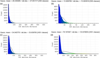
Terrain reconstruction results at Station D. (a): BA + Geometry; (b): proposed; (c): Loop-closed BA; (d): Classical-TR.

In Fig. 11, the mean values in the proposed algorithm, BA + Geometry, Loop-closed BA and Classical-TR methods were 13.9, 20.2, 34.0 and 79.1 mm, respectively, while the standard deviations were 15.8, 37.1, 35.6 and 133.7, respectively.
Comparisons of the results above-mentioned methods at Stations LE00306 and LE00308 were also made, and the results are presented in Table IV.
The compared results of the terrain descriptions at three stations based on the different methods.

Loop-closed BA could not be used at Station LE00306 because there was only one pair of Navcam images. The results in Table IV indicate that the proposed algorithm can improve the reconstruction precision with the stereo Navcam pair and the stereo Hazcam pair.
5.2.2. Visual pose prediction
In practice, there are a large number of visual pose prediction results for the Yutu-2 rover at any one station based on the terrain products. After accounting for the moving distance, obstacles and planning the path, a suitable pose from the above-noted prediction results can be selected. However, due to the slippage phenomenon caused by traversing on loose soil terrain or against steep slopes, Yutu-2 may not be able to move to the selected position. Hence, the accurate pose for Yutu-2 at the moved position should be viewed as inputs, which can be obtained by [Reference Ma, Liu, Sima, Wen, Peng and Jia1], as shown in columns “
 $X_{O}$
” and “
 $Y_{O}$
” of Table V. It is noted that Yutu-2’s attitude angles are obtained from the telemetry data (Sun sensor), as shown in columns “
 $\gamma _{y}$
”, “
 $\gamma _{p}$
” and “
 $\gamma _{r}$
” of Table V. Then, the rover’s pitch angle
 $\hat{\gamma }_{p}$
and roll angle
 $\hat{\gamma }_{r}$
can be recalculated by using the proposed algorithm with the terrain products, as shown in columns “
 $\hat{\gamma }_{p}$
” and “
 $\hat{\gamma }_{r}$
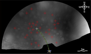
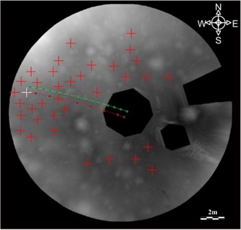
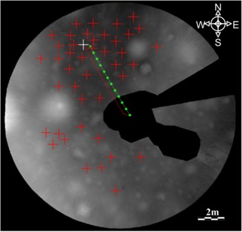
” of Table V. The path planning results for Stations S1, LE00210 and LE00309 are shown in Figs. 12, 13 and 14.
Measured angles and calculated angles of the rover at three stations.

Path planning results for position S1 (background: DEM).

Path planning results for position LE00210 (background: DEM).

Path planning results for position LE00309 (background: DEM).

From columns “
 ${\unicode[Times]{x03B3}} _{\mathrm{p}}$
” and “
 ${\unicode[Times]{x03B3}} _{\mathrm{r}}$
” of Table V, the rover pose at the current position meets the set requirement for entering the sleeping mode. In other words, the Yutu-2 rover must stop working and be ready to enter the sleeping mode at the corresponding given location. From the columns “
 $\hat{{\unicode[Times]{x03B3}} }_{\mathrm{p}}$
” and “
 $\hat{{\unicode[Times]{x03B3}} }_{\mathrm{r}}$
” or “
 ${\unicode[Times]{x03B4}} {\unicode[Times]{x03B3}} _{\mathrm{p}}$
” and “
 ${\unicode[Times]{x03B4}} {\unicode[Times]{x03B3}} _{\mathrm{r}}$
” of Table V, the predicted visual pose for Yutu-2 can be relatively stable. In Figs. 12, 13 and 14, the green line represents the moving path, the red line represents the planning path with the red crosses at the potential locations for the rover’s sleeping mode and the white cross as the selected location.
It is noted that the sleeping setup procedure of the Yutu-2 rover does not require timeliness of the calculation result because to access the calculating efficiency, the calculation times of the proposed algorithm from the process of inputting the stereo image to the calculation of the Yutu-2 rover pose are approximately 2.5 to 4.3 min. The calculation environment is an Intel(R) Core(TM) i5@2.50 GHz, 2 GB windows system.
6. Conclusions
A visual pose prediction method to set a sleeping mode for the Yutu-2 rover is proposed in this paper. The core of the paper is a multiview block BA model, which can solve the precise terrain reconstruction problem by using multisensor data. In this procedure, the precision loss phenomenon for terrain reconstruction with the Navcam images and the rotation angles of the head and the mast mechanism can be avoided when the hazard cameras system is used. The movement mechanism systems in the Yutu-2 rover belonged to a kind of multijoint rotary platform. The multiview block BA model based on the multisensor images can be considered to be a new solution to the precise terrain reconstruction problem on the multijoint rotary platform. Meanwhile, the exterior orientation parameters of the Navcam/Hazcams can be viewed as pseudo-observations, and a much more complete formula of the measurement errors for the 3D coordinates in a stereo camera system is given in this work, which can be used in further study on the terrain reconstruction problem. On this basis, a pose prediction method for the Yutu-2 rover based on terrain products is given. The experimental results in the simulation field and in the lunar mission demonstrated the following:
-
The prediction precision of the rover pose could meet the set requirement for entering the sleeping mode of the Yutu-2 rover. The average difference values of
$\gamma _{p}$
and
$\gamma _{r}$
were -0.19 degrees and 0.29 degrees, respectively. The proposed algorithm has been successfully used in CE-4 mission operations. -
The mean absolute errors of the check points in the proposed algorithm, BA + Geometry [Reference Ma, Liu, Sima, Wen, Peng and Jia1], CAHVOR [Reference Di and Li17], Classical-TR [Reference Wang, Wan, Gou, M.Peng, Di, Li, Yu, Wang and Cheng4, Reference Li, Squyres, Arvidson, Archinal, Bell, Cheng and Golombek6–Reference Liu, Di, Peng, Wan, Liu and Li8] and ISC [Reference Zhang, Liu, Ma, Qi, Ma and Yang19] were 10.4 11.3 mm, 19.3 20.4 and 20.2 mm over the range of
$L$
from 2.0 to 6.1 m, respectively. Thus, the proposed algorithm achieved more precise terrain results than BA + Geometry, CAHVOR, Classical-TR and ISC.


The proposed algorithm’s assumption is that the front and back wheels are stressed uniformly, which is appropriate in most cases. However, the proposed algorithm will not work well when there is a slippage phenomenon caused by traversing loose soil terrain or against steep slopes (especially when in craters) or in a shadow or overexposed location. In future research, the computing efficiency of the visual pose prediction method should be improved and it should be combined with other tools, such as a soil attribute prediction and classification system and soil mechanics theory. In addition, the estimated Navcam pose parameters based on the proposed algorithm will be affected, or even severely distorted, when the tie points are contaminated by gross errors or outliers. Hence, future studies of the proposed algorithm are also needed to detect outliers under certain weighting conditions [Reference Ma, Liu and Li29] and the total least squares solution [Reference Gu, Tu, Tang and Luo30].
China plans to send other rovers to the moon in future missions, such as Chang’E-7 and Chang’E-8. These rovers will also be equipped with a stereo vision system. The proposed algorithm is not only used on the CE-4 Yutu-2 rover but can also be used for setting up sleeping mode for the other lunar rovers.
Financial support
This work was supported in part by the National Natural Science Foundation of China under Grants 42071447 and 41601494, in part by the Key Laboratory of Earth Observation and Geospatial Information Science under Grant 201901, and in part by the Natural Science Foundation Guidance Program of Liaoning Province under Grant 20180550849.
Competing interests declaration
The authors declare that they have no known competing financial interests or personal relationships that could have appeared to influence the work reported in this paper
Author contributions
Youqing Ma contributed to the conception of the study; Song Peng and Youqing Ma performed the experiments; Xinchao Xu contributed significantly to the analysis and manuscript preparation; Song Peng, Youqing Ma and Xinchao Xu performed the data analyses and wrote the manuscript; Yang Jia and Shaochuang Liu helped perform the analysis with constructive discussions.