I. INTRODUCTION
Microstrip patch antennas are used in the wide range of applications such as aircraft, satellite, missiles, and land vehicles and in small portable wireless communication equipment's due to their compactness, light weight, low-profile, and relative ease of fabrication method [Reference Kumar and Singh1–Reference Liu, Ghassemlooy, Sambell, Danaher and Smith3]. The main shortcomings of these antennas are narrow bandwidth and low gain. These shortcomings can be overcome in by proper design of an antenna, and especially using proper substrate thickness and dielectric constant as well as a proper way of feeding [Reference Vilovic, Burum and Brailo4]. Various techniques have been proposed to improve the bandwidth operation of the microstrip elements, and the most common technique using feeding according element through an aperture cut in a microstrip line ground plane [Reference Fortaki, Khedrouche, Bouttout and Benghalia5, Reference Ho and Hsu6]. Alternatively, aperture-coupling feeds are gaining popularity owing to a number of advantages, such as a greater bandwidth and efficiency, weak parasitic radiation in the useful direction with respect to conventionally feed antennas and optimal performance for both the feeding network and antenna element [Reference Fortaki, Khedrouche, Bouttout and Benghalia5]. With the increasing complexity of geometry and material property, designing these antennas requires more and more dedicated and sophisticated computer-aided-design (CAD) tools to predict the characteristics [Reference Ye, Yuan and Su7]. Various methods and commercial software are available for analysis and synthesis of microstrip antennas. These commercial design packages use computer intensive numerical methods such as, finite-element method, method of moment (MoM), finite-difference time-domain method, etc. These techniques require high computational resources and also take lots of computation time [Reference Bhagat, Pujara and Adhyaru8]. In the present-day scenario, neural network models are used extensively for wireless communication engineering, which eliminate the complex and time-consuming mathematical procedure of designing, such as the MoMs [Reference Bose and Gupta9]. The neural networks in conjunction with spectral domain approach (SDA) was firstly proposed by Mishra and Patnaik [Reference Mishra and Patnaik10], to calculate the complex resonant frequency and the input impedance [Reference Mishra and Patnaik11] of rectangular microstrip antenna, this approach is named neurospectral method [Reference Bedra, Benkouda and Fortaki12]. This is the main reason for selecting the neurospectral to estimate the resonant frequency and half-power bandwidth of a rectangular microstrip patch over the ground plane with rectangular aperture. To the best of the author's knowledge, the artificial neural network (ANN) models for predicting the characteristics of microstrip patches over the ground plane with rectangular aperture have not been thoroughly reported in the open literature.
The objective of this work is to present an integrated approach based on ANNs and SDA. We introduce the ANNs in the analysis of a rectangular microstrip patch over a ground plane with rectangular aperture to reduce the complexity of the spectral approach and to minimize the central processing unit (CPU) time necessary to obtain the numerical results. The neurospectral model is simple, easy to apply, and very useful for antenna engineers to predict both resonant frequency and half-power bandwidth.
II. THEORETICAL FORMULATION
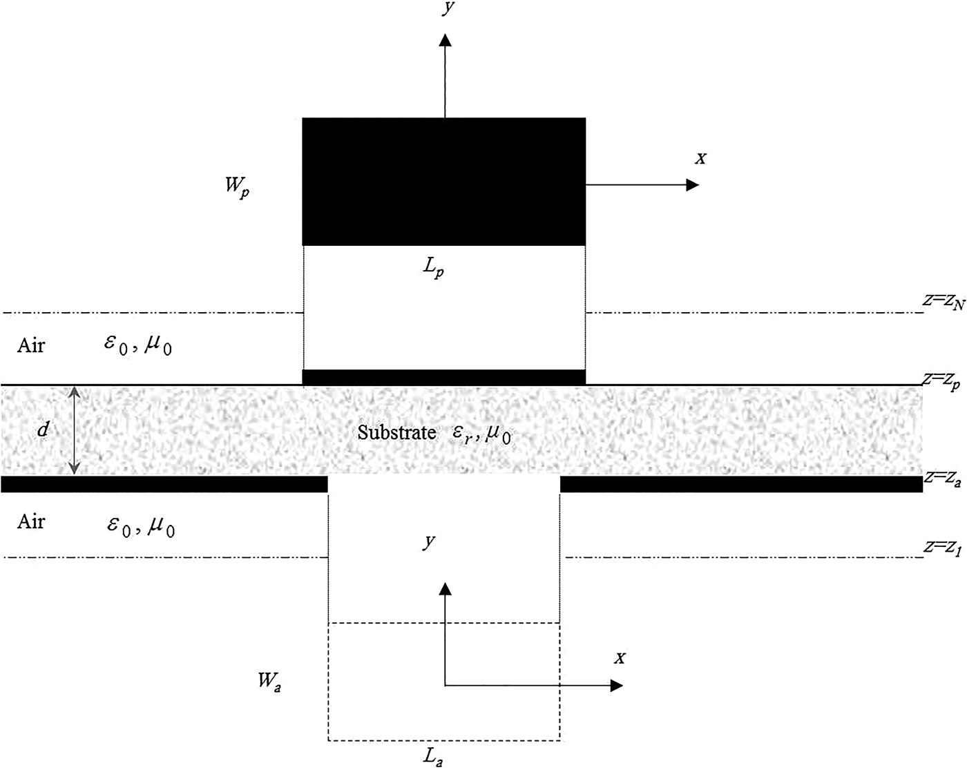
The geometry of the considered structure is shown in Fig. 1. We have a rectangular microstrip patch of length L p along the x-direction and width W p along the y-direction over the ground plane with a rectangular aperture of length L a and width W a. Both the center of the patch and the center of aperture have the coordinate value (x, y) = (0, 0). Also, the metallic patch and the ground plane are assumed to be perfect electric conductors of negligible thickness. The dielectric layer of thickness d is characterized by the free-space permeability µ0 and the permittivity ε0, εr (ε0 is the free-space permittivity and the relative permittivity εr can be complex to account for dielectric loss).
Geometrical structure of a tunable rectangular microstrip patch over a ground plane with rectangular aperture.

The ambient medium is air with constitutive parameters μ0 and ε0. All fields and currents are time harmonic with the εiωt time dependence suppressed. The transverse fields inside the substrate region can be obtained via the inverse vector Fourier transforms as [Reference Fortaki, Khedrouche, Bouttout and Benghalia5, Reference Fortaki and Benghalia13]
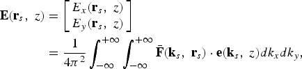 $$\eqalign{{\bf E}\lpar {{\bf r}_s}\comma \; z\rpar & =\left[{\matrix{ {{E_x}\lpar {{\bf r}_s}\comma \; z\rpar } \cr {{E_y}\lpar {{\bf r}_s}\comma \; z\rpar } \cr } } \right]\cr & =\displaystyle{1 \over {4{\pi ^2}}}\int_{ - \infty }^{+\infty } {\int_{ - \infty }^{+\infty } {\bar{\bf F}\lpar {{\bf k}_s}\comma \; {{\bf r}_s}\rpar } } \cdot {\bf e}\lpar {{\bf k}_s}\comma \; z\rpar d{k_x}d{k_y}\comma \; }$$
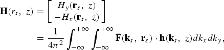 $$\eqalign{{\bf H}\lpar {r_s}\comma \; z\rpar & =\left[{\matrix{ {{H_y}\lpar {{\bf r}_s}\comma \; z\rpar } \cr { - {H_x}\lpar {{\bf r}_s}\comma \; z\rpar } \cr } } \right]\cr & =\displaystyle{1 \over {4{\pi ^2}}}\int_{ - \infty }^{+\infty } {\int_{ - \infty }^{+\infty } {\bar{\bf F}\lpar {{\bf k}_s}\comma \; {{\bf r}_s}\rpar } } \cdot {\bf h}\lpar {{\bf k}_s}\comma \; z\rpar d{k_x}d{k_y}\comma \; }$$
where  $\bar{\bi F}\lpar {{\bf k}_s}\comma \; {{\bf r}_s}\rpar $ is the kernel of the vector Fourier-transforming domain (VFTD) [Reference Fortaki, Khedrouche, Bouttout and Benghalia5, Reference Fortaki and Benghalia13]
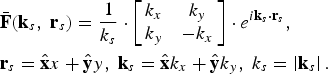 $$\eqalign{& \bar{\bf F}\lpar {{\bf k}_s}\comma \; {{\bf r}_s}\rpar =\displaystyle{1 \over {{k_s}}} \cdot \left[{\matrix{ {{k_x}} & {{k_y}} \cr {{k_y}} & { - {k_x}} \cr } } \right]\cdot {e^{i{{\bf k}_s} \cdot {{\bf r}_s}}}\comma \; \cr & {{\bf r}_s}=\hat{\bf x}x+\hat{\bf y}y\comma \; {{\bf k}_s}=\hat{\bf x}{k_x}+\hat{\bf y}{k_y}\comma \; {k_s}=\left\vert {{{\bf k}_s}} \right\vert .}$$
The relation which related the current j(ks), j0(ks) on the conducting patch (ground plane with rectangular aperture) to the electric field on the corresponding interface e(ks, z p), and e(ks, z a) given by
 $${\bf e}\lpar {{\bf k}_s}{\rm\comma \; }{z_p}\rpar =\bar{\bf G}\lpar {{\bf k}_s}\rpar \cdot {\bf j}\lpar {{\bf k}_s}\rpar +\bar{\bf \Psi}\lpar {{\bf k}_s}\rpar \cdot {\bf e}\lpar {{\bf k}_s}{\rm\comma \; }{z_{\rm a}}\rpar {\rm\comma \; }$$
 $${{\bf j}_0}\lpar {{\bf k}_s}\rpar =- \bar{\bf \Phi}\lpar {{\bf k}_s}\rpar \cdot {\bf j}\lpar {{\bf k}_s}\rpar - \bar{\bf \Upsilon}\lpar {{\bf k}_s}\rpar \cdot {\bf e}\lpar {{\bf k}_s}{\rm\comma \; }0\rpar .$$
The four 2 × 2 diagonal matrices  $\bar{\bf G}\lpar {{\bf k}_s}\rpar $,
 $\bar{\bf \Psi}\lpar {{\bf k}_s}\rpar $,
 $\bar{\bf \Phi}\lpar {{\bf k}_s}\rpar $, and
 $\bar{\bf Y}\lpar {{\bf k}_s}\rpar $ stand for a set of dyadic Green's functions in the vector Fourier transform domain. It is to be noted that
 $\bar{\bf G}\lpar {{\bf k}_s}\rpar $ is related to the patch current and
 $\bar{\bf Y}\lpar {{\bf k}_s}\rpar $ is related to the aperture field.
 $\bar{\bf \Psi}\lpar {{\bf k}_s}\rpar $ and
 $\bar{\bf \Phi}\lpar {{\bf k}_s}\rpar $ represent the interactions between the patch current and aperture field. In equations (5) and (6), the unknowns are j(ks) and e(ks, z a). Another possible choice in the analysis of microstrip patches over the ground planes with apertures is to consider j0(ks) as unknown instead of e(ks, z a). It is anticipated, however, that a very large number of terms of basis functions would be needed for the expansion of the current j0(rs) on the ground plane with aperture because of the wide conductor area. Hence, it is better to apply the Galerkin procedure to the unknown E(rs, z a) field at the aperture [Reference Fortaki and Benghalia13].
The transverse electric field at the plane of the patch and the surface current density on the ground plane with a rectangular aperture can be obtained from equations (4) and (5), respectively, via the inverse vector Fourier transforms as
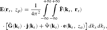 $$\eqalign{& {\bf E}\lpar {{\bf r}_s}\comma \; {z_p}\rpar = \displaystyle{1 \over {4{\pi ^2}}}\int\limits_{ - \infty }^{ + \infty } {\int\limits_{ - \infty }^{ + \infty } {\bar {\bf F} \lpar {{\bf k}_s}\comma \; {{\bf r}_s}\rpar } } \cr & \; \cdot \left[{\bar {\bf G} \lpar {{\bf k}_s}\rpar \cdot {\bf j}\lpar {{\bf k}_s}\rpar + \bar {\bf \Psi } \lpar {{\bf k}_s}\rpar \cdot {\bf e}\lpar {{\bf k}_s}\comma \; {z_a}\rpar } \right]d{k_x}d{k_y}\comma \; }$$
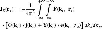 $$\eqalign{& {{\bf J}_0}\lpar {{\bf r}_s}\rpar = - \displaystyle{1 \over {4{\pi ^2}}}\int\limits_{ - \infty }^{ + \infty } {\int\limits_{ - \infty }^{ + \infty } {\bar {\bf F} \lpar {{\bf k}_s}\comma \; {{\bf r}_s}\rpar } } \cr & \; \cdot \left[{\bar \Phi \lpar {{\bf k}_s}\rpar \cdot {\bf j}\lpar {{\bf k}_s}\rpar + \bar {\bf Y} \lpar {{\bf k}_s}\rpar \cdot {\bf e}\lpar {{\bf k}_s}\comma \; {z_a}\rpar } \right]d{k_x}d{k_y}.}$$
Boundary conditions require that the transverse electric field of equation (6) vanishes on the perfectly conducting patch and the current of equation (7) vanishes off the ground plane, to give the following coupled integral equations for the patch current and aperture field:
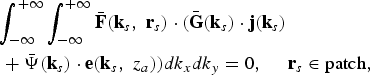 $$\eqalign{& \int_{ - \infty }^{ + \infty } {\int_{ - \infty }^{ + \infty } {\bar {\bf F} \lpar {{\bf k}_s}\comma \; {{\bf r}_s}\rpar } } \cdot \lpar \bar {\bf G} \lpar {{\bf k}_s}\rpar \cdot {\bf j}\lpar {{\bf k}_s}\rpar \cr & \; + \bar {\bf \Psi } \lpar {{\bf k}_s}\rpar \cdot {\bf e}\lpar {{\bf k}_s}\comma \; {z_a}\rpar \rpar d{k_x}d{k_y} = 0\comma \; \quad {{\bf r}_s} \in {\rm patch}\comma \; }$$
 $$\eqalign{& \int_{ - \infty }^{ + \infty } {\int_{ - \infty }^{ + \infty } {\bar {\bf F} \lpar {{\bf k}_s}\comma \; {{\bf r}_s}\rpar } } \cdot \lpar \bar \Phi \lpar {{\bf k}_s}\rpar \cdot {\bf j}\lpar {{\bf k}_s}\rpar \cr & \; + \bar {\bf Y} \lpar {{\bf k}_s}\rpar \cdot {\bf e}\lpar {{\bf k}_s}\comma \; {z_a}\rpar \rpar d{k_x}d{k_y} = 0\comma \; \quad {r_s} \in {\rm aperture}}.$$
The first step in the moment method solution of equations (8) and (9) is to expand both the patch current j(ks) and aperture field E(ks, z a) as
 $${\bf j}\lpar {{\bf k}_s}\rpar =\sum\limits_{n=1}^N {{a_n}} \left[{\matrix{ {{J_{xn}}\lpar {{\bf r}_s}\rpar } \cr 0 \cr } } \right]+\sum\limits_{m=1}^M {{b_m}} \left[{\matrix{ 0 \cr {{J_{ym}}\lpar {{\bf r}_s}\rpar } \cr } } \right]\comma \;$$
 $${\bf E}\lpar {{\bf r}_s}{\rm\comma \; }{z_a}\rpar =\sum\limits_{p=1}^P {{c_p}} \left[{\matrix{ {{E_{xp}}\lpar {{\bf r}_s}\rpar } \cr 0 \cr } } \right]+\sum\limits_{q=1}^Q {{d_q}} \left[{\matrix{ 0 \cr {{E_{yq}}\lpar {{\bf r}_s}\rpar } \cr } } \right]\comma \;$$
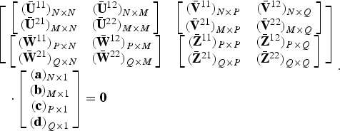
where J xn, J ym, E xp, and E yq are the known basis functions and a n, b m, c p, and d q are the mode expansion coefficients to be sought. Using the technique known as the moment method [Reference Fortaki and Benghalia13], with weighting modes chosen identical to the expansion modes, equations (8) and (9) are reduced to a system of linear equations which can be written compactly in matrix form as
 $$\eqalign{&\left[\matrix{ {\left[{\matrix{ {{{\lpar {{\bar{\bf U}}^{ 11}}\rpar }_{N \times N}}} & {{{\lpar {{\bar{\bf U}}^{ 12}}\rpar }_{N \times M}}} \cr {{{\lpar {{\bar{\bf U}}^{ 21}}\rpar }_{M \times N}}} & {{{\lpar {{\bar{\bf U}}^{ 22}}\rpar }_{M \times M}}} \cr } } \right]} & {\left[{\matrix{ {{{\lpar {{\bar{\bf V}}^{ 11}}\rpar }_{N \times P}}} & {{{\lpar {{\bar{\bf V}}^{ 12}}\rpar }_{N \times Q}}} \cr {{{\lpar {{\bar{\bf V}}^{ 21}}\rpar }_{M \times P}}} & {{{\lpar {{\bar{\bf V}}^{ 22}}\rpar }_{M \times Q}}} \cr } } \right]} \cr {\left[{\matrix{ {{{\lpar {{\bar{\bf W}}^{ 11}}\rpar }_{P \times N}}} & {{{\lpar {{\bar{\bf W}}^{ 12}}\rpar }_{P \times M}}} \cr {{{\lpar {{\bar{\bf W}}^{ 21}}\rpar }_{Q \times N}}} & {{{\lpar {{\bar{\bf W}}^{ 22}}\rpar }_{Q \times M}}} \cr } } \right]} & {\left[{\matrix{ {{{\lpar {{\bar{\bf Z}}^{ 11}}\rpar }_{P \times P}}} & {{{\lpar {{\bar{\bf Z}}^{ 12}}\rpar }_{P \times Q}}} \cr {{{\lpar {{\bar{\bf Z}}^{ 21}}\rpar }_{Q \times P}}} & {{{\lpar {{\bar{\bf Z}}^{ 22}}\rpar }_{Q \times Q}}} \cr } } \right]} } \right]\cr & \quad\cdot \left[\matrix{ {{{\lpar {\bf a}\rpar }_{N \times 1}}} \cr {{{\lpar {\bf b}\rpar }_{M \times 1}}} \cr {{{\lpar {\bf c}\rpar }_{P \times 1}}} \cr {{{\lpar {\bf d}\rpar }_{Q \times 1}}} } \right]={\bf 0}}.$$
The elements of the matrix  ${\lpar \bar{\bf U}\rpar _{\lpar N+M\rpar \times \lpar N+M\rpar }}$,
 ${\lpar \bar{\bf V}\rpar _{\lpar N+M\rpar \times \lpar P+Q\rpar }}$,
 ${\lpar \bar{\bf W}\rpar _{\lpar P+Q\rpar \times \lpar N+M\rpar }}$, and
 ${\lpar \bar{\bf Z}\rpar _{\lpar P+Q\rpar \times \lpar P+Q\rpar }}$ are given in [Reference Fortaki and Benghalia13].
It is easy to show that the entire matrix in equation (12) is a symmetric matrix. For the existence of a non-trivial solution of equation (12), we must have
 $${\rm det\lpar }\bar{\bf \Omega}\lpar f\rpar \rpar ={\rm 0\comma \; }\quad \bar{\bf \Omega}=\left[{\matrix{ {\bar{\bf U}} & {\bar{\bf V}} \cr {\bar{\bf W}} & {\bar{\bf Z}} \cr } } \right].$$
Equation (13) is the characteristic equation for the complex resonant frequency f = f r + if i of the generalized microstrip structure illustrated in Fig. 1. f r is the resonant frequency and 2f i/f r is the half-power bandwidth of the structure.
In the following section, a basic ANN is described briefly and the application of neural network to the prediction the resonant characteristics of the microstrip antenna are then explained.
III. NEURAL NETWORK MODELING
ANN learns relationships among sets of input–output data which are characteristic of the device under consideration. It is a very powerful approach for building complex and non-linear relationship between a set of input and output data [Reference Guney, Yildiz, Kaya and Turkmen14].
ANNs have been used frequently in signal-processing applications, speech and pattern recognition, remote sensing, etc. for the past two decades [Reference Chopra and Chandrasekhar15]. Ability, adaptive capability and ease of implementation have made ANN a popular tool for many design problems in today's communication world [Reference Bose and Gupta9]. More importantly, ANNs can generalize and respond correctly to slightly deviant input values, not presented during the training process [Reference Kulshrestha, Chheda, Chakrabarty, Jyoti and Sharma16]. These networks directly give a good approximation of simulation and measured value, thereby avoiding the need for possibly a more complex and time-consuming conventional problem-specific algorithm [Reference Bose and Gupta9]. In the present scenario, neural network models are used extensively for wireless communication engineering, which eliminates the complex and time-consuming mathematical and simulation procedures for designing antennas [Reference Mishra and Patnaik10, Reference Mishra and Patnaik17, Reference Patnaik and Mishra18].
Multilayer perceptrons (MLPs) have been applied successfully to solve some difficult and diverse problems by training them in a supervised manner with a highly popular algorithm known as the error back propagation algorithm [Reference Kumar and Gunasekaran19].
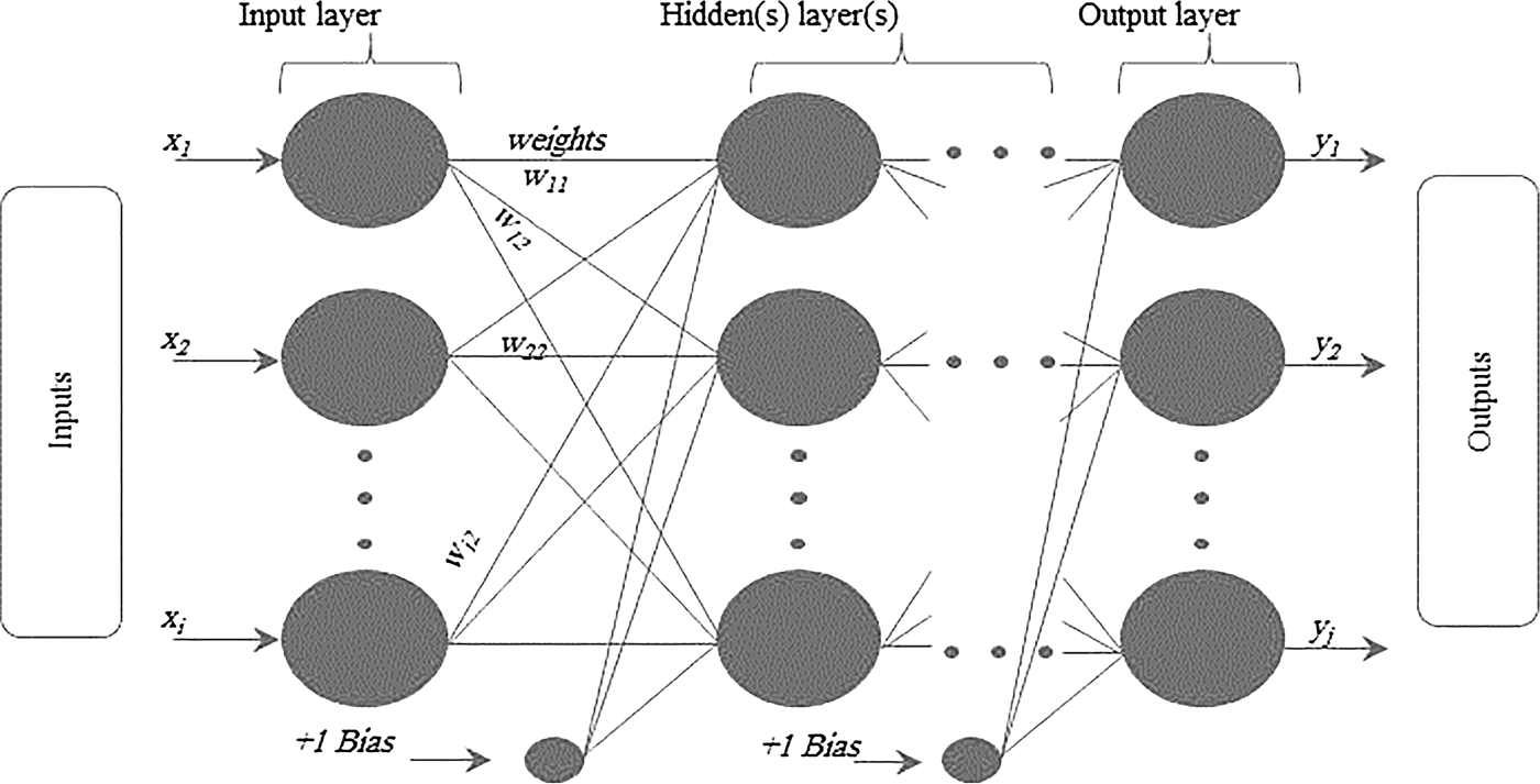
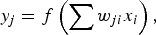
As shown in Fig. 2, the MLP consists of an input layer, one or more hidden layers, and an output layer. Neurons in the input layer only act as buffers for distributing the input signals x i to neurons in the hidden layer. Each neuron in the hidden layer sums its input signals x i after weighting them with the strengths of the respective connections w ji from the input layer and computes its output y j as a function f of the sum, namely
 $${y_j}=f\left( \sum w_{ji}{x_i} \right )\comma \;$$
where f can be a simple threshold function or a sigmoid or hyperbolic tangent function [Reference Guney and Gultekin20]. The output of neurons in the output layer is computed similarly.
General form of multilayered perceptrons.
Training of a network is accomplished through adjustment of the weights to give the desired response via the learning algorithms. An appropriate structure may still fail to give a better model unless the structure is trained by a suitable learning algorithm. A learning algorithm gives the change Δw ji(k) in the weight of a connection between neurons i and j at time k. The weights are then updated according to the formula
 $${w_{ji}}\lpar k+1\rpar ={w_{ji}}\lpar k\rpar +\Delta {w_{ji}}\lpar k+1\rpar.$$
MLP can be trained using many different learning algorithms [Reference Haykin21]. In this paper, the following back propagation learning algorithm described briefly was used to train the MLP.
The back-propagation algorithm is based on the error correction learning rule. Basically, error back propagation learning consists of two passes through the different layers of the network, a forward pass and a backward pass. In the forward pass, an activity pattern applies to the sensor nodes of the network, and its effect propagates through the network layer by layer [Reference Haykin21]. Finally, a set of outputs is produced as the actual response of the network. During the forward pass, the synaptic weights of the networks are all fixed. During the backward pass, on the other hand, all the synaptic weights are adjusted in accordance with an error correction rule. The actual response of the network is subtracted from a desired response to produce an error signal. This error signal is then propagated backward through the network against the direction of synaptic connections. The synaptic weights are adjusted to make the actual response of the network move closer to the desired response in a statistical sense [Reference Kumar and Gunasekaran19]. ANN model's accuracy depends on the amount of data presented to it during training. A well-distributed, accurately simulated or measured and sufficient data are the basic requirement to obtain an efficient model.
The data sets used in this paper were obtained from the method described in the previous section. A total of 250 data sets used to train the neuronal model. 112 data sets, which are completely different from training data sets, were used to test the neural network model. The most suitable network configuration found was 6, 12, 12, and 2 for the input layer, the first and second hidden layers, and the output layer, respectively. The tangent sigmoid and logarithmic sigmoid activation functions were used in the first and second hidden layers, respectively. The linear activation function was used in the input and output layers. Initial weights of the neural models were set up randomly, with learning rate = 0.5, goal = 0.0001, was trained for 5000 epochs. The CPU time taken by the spectral domain to give the both resonant frequency and half-power bandwidth for each input set is more than 5 min; it depends on three initial values used in Muller's algorithm for not seeking of the characteristic equation. The overall time to get the ANN trained is in the range of 3–4 h, depending on the required accuracy. All the numerical results presented in this paper we obtained on a Pentium IV computer with a 3.20-GHz processor and a total RAM memory of 2 GB.
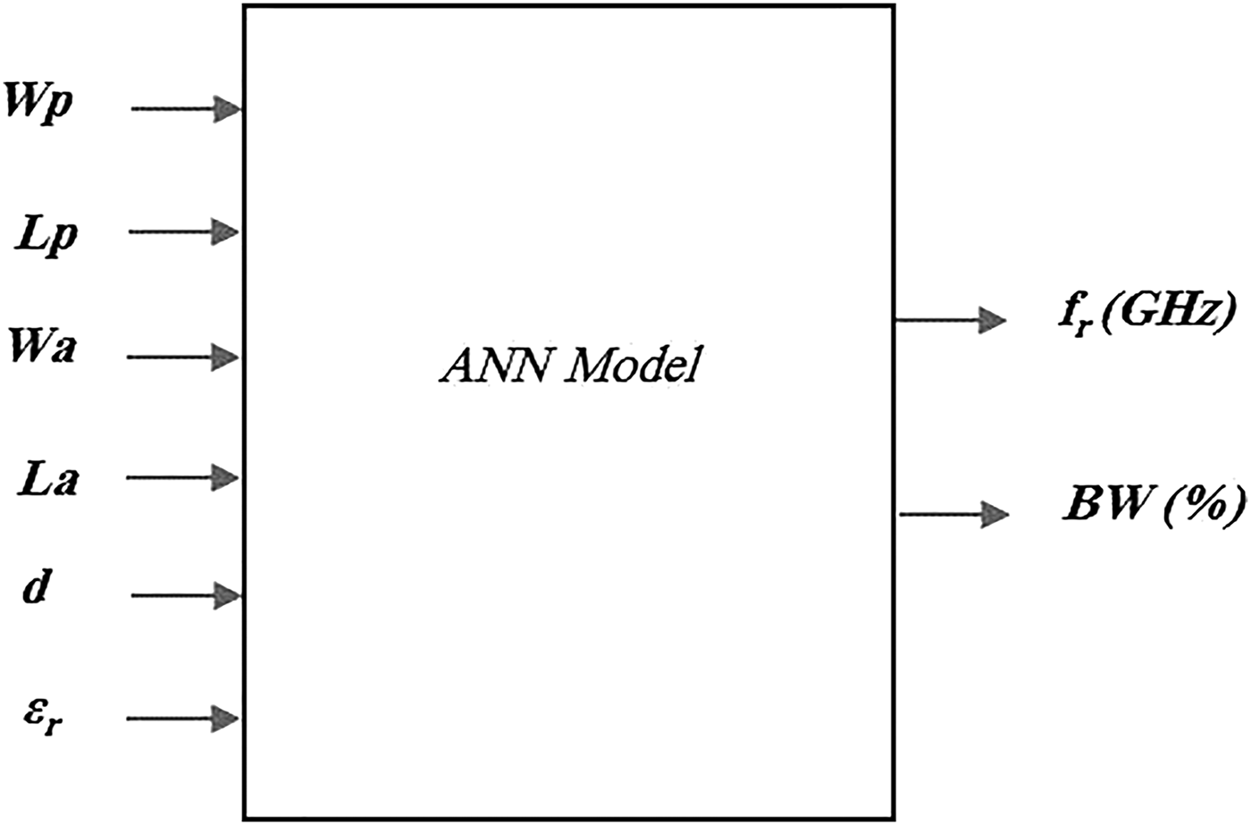
The resonant characteristics of the antenna are obtained as a function of patch dimensions (L p, W p), aperture dimensions (L a, W a), height of the dielectric substrate (d), and dielectric constants of the material (εr) “see Fig. 3”.
Neural model for calculating the resonant frequency and half-power bandwidth of rectangular microstrip antenna without rectangular aperture in the ground plane.
IV. NUMERICAL RESULTS AND DISCUSSION
One purpose of this work is to study the influence of some geometric parameters of the structure and the behavior of the final response. From these data an ANN is trained to predict the response of the structure due to the change of the considered parameter, within a given region of interest.
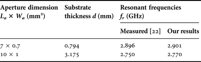
To confirm the computation accuracy, our numerical results are compared with experimental data previously published [Reference Aksun, Chuang and Lo22]. It can be clearly seen from Table 1 that our results calculated using the neural model proposed in this paper are better than those predicted by other scientists. The very good agreement between the measured values and our computed resonant frequency values supports the validity of the neural model even with the limited data set.
Comparison of measured and calculated resonant frequencies of a rectangular microstrip antenna with a rectangular aperture in the ground plane; L p × W p = 34 mm × 30 mm, εr = 2.62.
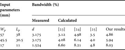
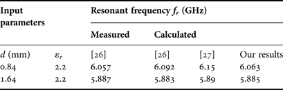
With the aim of confirming the computation accuracy for the case of rectangular microstrip antenna (without aperture in the ground plane), we compare our results in Tables 2 and 3 with both experimental and theoretical data previously published [Reference Chang, Long and Richards23–27]. The comparison is done for different antenna parameters.
Comparison of the calculated bandwidth with measured and calculated data, for a rectangular microstrip patch antenna without aperture in the ground plane, εr = 2.33.
Comparison of calculation and measured resonant frequencies for rectangular microstrip antenna without aperture in the ground plane; with L p = 25.08 mm, W p = 15.438 mm.
From Table 2 it is observed that the bandwidths of a rectangular microstrip antenna computed by the present approach are closer to the experimental [Reference Chang, Long and Richards23] and theoretical [Reference Chew and Liu24, Reference Pozar25] values. In Table 3, the resonant frequencies obtained by the present approach are compared with the previous results [Reference Aouabdia, Belhadj-Tahar, Alquie and Benabdelaziz26, 27]. The comparison shows that the resonant frequencies computed by the present method are in very good agreement with the measured data for a rectangular patch printed on a single substrate.
In Fig. 4, we compare our results with theoretical data previously published [Reference Fortaki, Khedrouche, Bouttout and Benghalia5]. The comparison is done in two different aperture dimensions. It can be seen that the resonant frequencies of the patches over the ground planes without aperture are larger than those obtained with aperture. These behaviors agree very well with those reported in the previous works [Reference Fortaki, Khedrouche, Bouttout and Benghalia5, Reference Fortaki and Benghalia13, Reference Messai, Benkouda, Amir, Bedra and Fortaki28].
Resonant frequencies of rectangular patches over the ground planes with and without rectangular apertures, (a) L a × W a = 0.25W p × 0.5W p, (b) L a × W a = 0.5W p × 0.25W p; d = 1 mm, εr = 2.35, L p = 1.5W p.
Figure 5 predicts the influence of the aperture dimensions on the half-power bandwidth of the rectangular microstrip patch antenna for different antenna parameters. It can be seen that the bandwidth of the patches over the ground planes without aperture are larger than those obtained with aperture.
Half-power bandwidths of rectangular patches over the ground planes with and without rectangular apertures; d = 1mm, εr = 2.35, and L p = 1.5W p.
Figure 6 presents numerical results for the resonant frequencies of rectangular microstrip patches over the ground planes with and without rectangular apertures. Note that, the results obtained for the resonant frequencies without aperture (W a × L a = 0 × 0 mm2) lie around 10.89% above those obtained when W a × L a = 2 × 4 mm2 and around 31.48% above those obtained when W a × L a = 4 × 2 mm2.
Variation of the resonant frequencies of rectangular patches over the ground planes with and without rectangular apertures with the thickness of substrate; εr = 2.35, L p = 15 mm, and W p = 10 mm.
In Fig. 7, the results are presented for the bandwidths of the rectangular microstrip patches analyzed in Fig. 1. As seen in Figs 6 and 7, the presence of the aperture has a stronger effect on the resonant characteristics. Thus, the differences between the results obtained for the half-power bandwidths when W a × L a = 0 × 0 mm2 and those obtained when W a × L a = 2 × 4 mm2 reach 8.55%, and reach 32.14% for those obtained when W a × L a = 4 × 2 mm2. We conclude that the aperture length has a stronger effect on the resonant characteristics that the aperture width.
Variation of half-power bandwidths of rectangular patches over the ground planes with and without rectangular apertures with the thickness of substrate; εr = 2.35, L p = 15 mm, and W p = 10 mm.
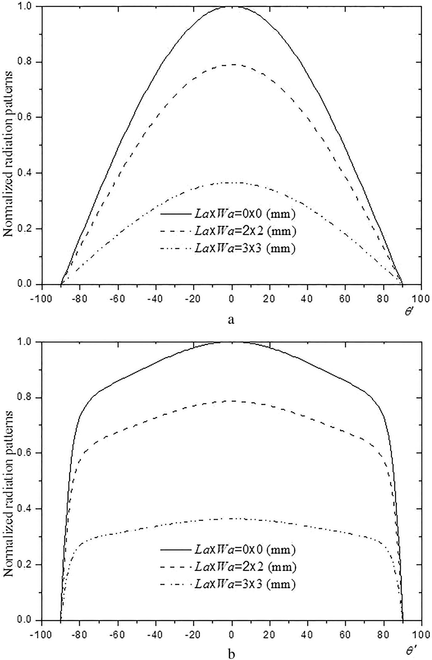
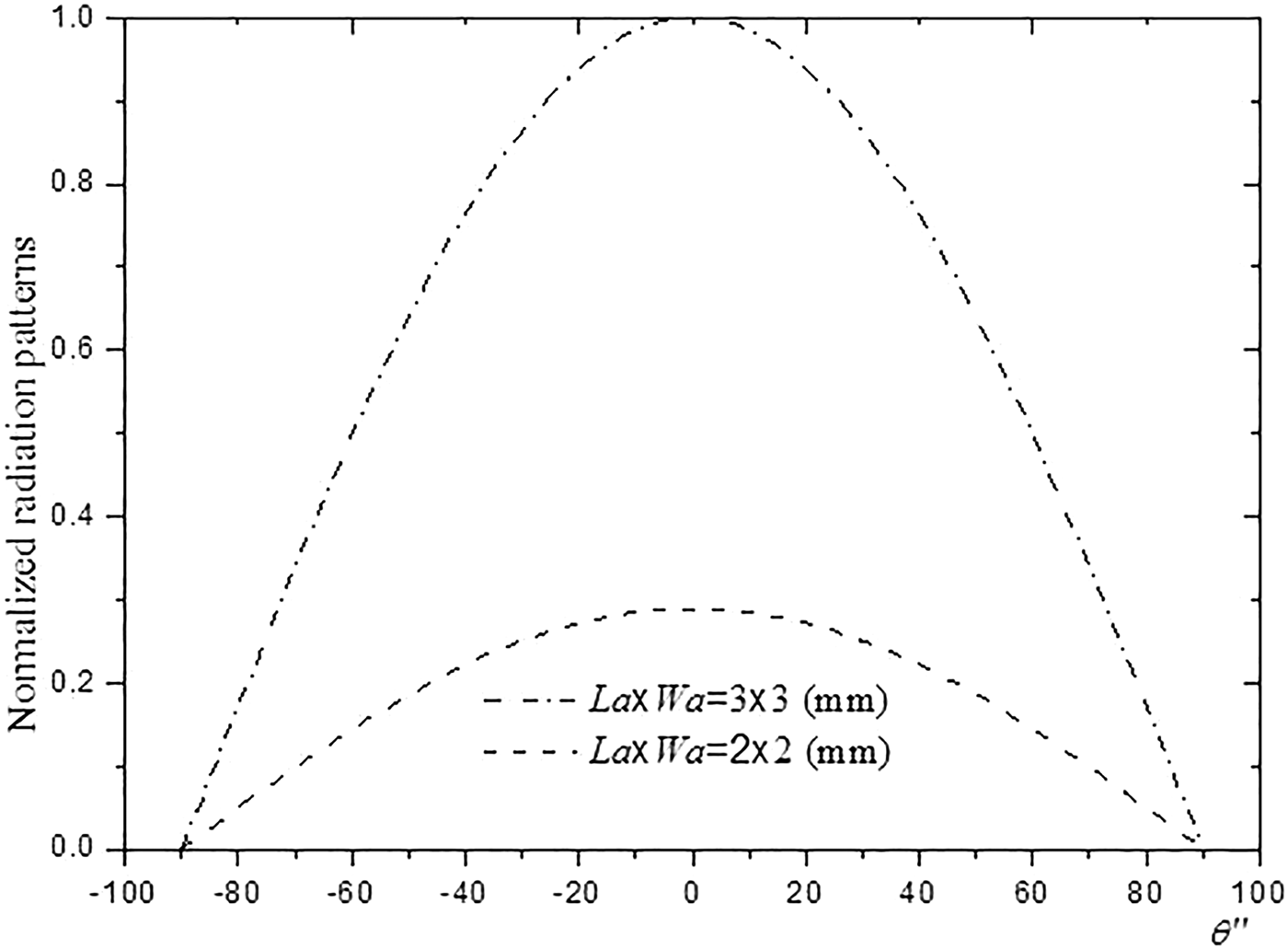
Figures 8 and 9, plots the radiation patterns in the E-plane (ϕ = 0) and H-plane (ϕ = π/2) of a rectangular microstrip patch over the ground planes with and without rectangular apertures in both the air half-space above the patch and the air half-space below the ground planes. The structure without aperture in the ground plane operates at a frequency of 5.411 GHz. The resonant frequencies of the structures with an aperture in the ground planes are 5.348 and 5.124 GHz for the aperture dimensions of L a × W a = 0.2W p × 0.2W p and L a × W a = 0.3W p × 0.3W p, respectively. Concerning the radiation above the patch, it is clear that it decreases with the increase of the size of the aperture. On the other hand, increasing the size of the aperture increases the radiation below the ground plane. Therefore, the radiation back onto the forward ratio is particularly important as the size of the aperture is wider. Let us note that for apertures considered in Fig. 8, the back radiation is very weak in front of that forward. Obviously, the effects of the back radiation can be always suppressed by the investment of a supplementary conductive plan below the ground plane containing the apertures. Then the resonance properties of the microstrip patch are possible with a suitable choice of the separation between the additional conducting plane and the ground plane. This has been proven experimentally by Losada [Reference Losada, Boix and Horno29] for the case of a circular patch on the ground plane with circular apertures.
Upper radiation patterns of rectangular patches over the ground planes with and without rectangular apertures (a) H-plane, (b) E-plane; with L p = 15 mm, W p = 10 mm, εr = 7, and d = 1 mm.
Lower H-plane radiation pattern of rectangular patches over the ground planes with and without rectangular apertures; with L p = 15 mm, W p = 10 mm, εr = 7, and d = 1 mm.
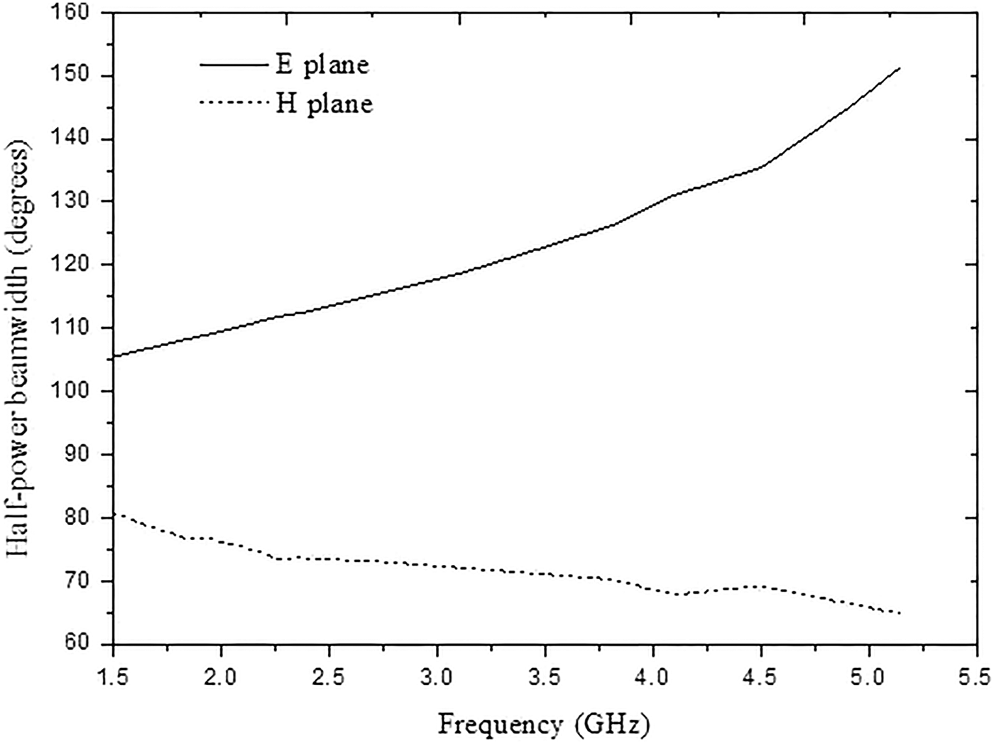
The variations of half-power beamwidth of the rectangular patch antenna with the resonant frequencies are shown in Fig. 10. The E-plane beamwidth of patch antenna increases by increasing the resonant frequencies, against the H-plane beamwidth decreases with increasing the resonance frequencies.
Half-power beamwidth of rectangular antenna versus the resonant frequencies when L p is varied; with W p = 57 mm, εr = 2.33, d = 3.175 mm, L a = 2 mm, and W a = 2 mm.
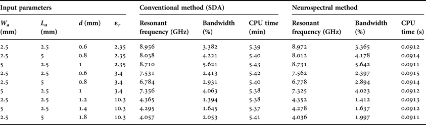
In Table 4, we compare our results obtained via the proposed neurospectral model with those obtained using the conventional SDA method. As well, to the resonant frequency and half-power bandwidth, we have also shown the CPU time in this table. It is clear that our resonant frequencies and bandwidths coincide with those obtained by the conventional moment method. Note that, the time required for obtaining the resonant frequency and half-power bandwidth using the neurospectral model is much less in comparison to the spectral domain method.
Comparison of our results obtained via the proposed neurospectral model with those obtained using the conventional spectral domain method, with W p × L p = 4 × 2 mm2.
V. CONCLUSION
A neural network-based CAD model can be developed for the analysis of a rectangular patch antenna, which is robust both from the angle of time of computation and accuracy. A distinct advantage of neuro-computing is that, after proper training, a neural network completely bypasses the repeated use of complex iterative processes for new cases presented to it. The single network structure can predict the results for patch antenna provided that input values are in the domain of training values. In the first example, a general design procedure for the microstrip antennas has been suggested using ANNs and this is demonstrated using the rectangular patch geometry. The spectral domain technique combined with the ANN method is several hundred times faster than the direct solution. This remarkable time gain makes the designing and training times negligible. Consequently, the neurospectral method presented is a useful method that can be integrated into a CAD tool, for the analysis, design, and optimization of practical shielded monolithic microwave-integrated circuit (MMIC) devices.
Appendix A
In this appendix, we appeared some details to reduce a system of linear equations which is written in Section II.
The elements of the matrix  ${\lpar \bar{\bf U}\rpar _{\lpar N+M\rpar \times \lpar N+M\rpar }}$, are given by
 $$\eqalign{& {\lpar {\bar {\bf U} ^{11}}\rpar _{kn}} = \int_{ - \infty }^{ + \infty } {\int_{ - \infty }^{ + \infty } {\displaystyle{1 \over {k_s^2 }}\left[{k_x^2 {G^e} + k_y^2 {G^h}} \right]{{\tilde J}_{xk}}} } \lpar \!- \!{{\bf k}_s}\rpar {{\tilde J}_{xn}}\lpar {{\bf k}_s}\rpar d{k_x}d{k_y}\comma \; }$$
 $$\eqalign{& {\lpar {\bar {\bf U} ^{12}}\rpar _{km}} = \int_{ - \infty }^{ + \infty } {\int_{ - \infty }^{ + \infty } {\displaystyle{{{k_x}{k_y}} \over {k_s^2 }}\left[{{G^e} - {G^h}} \right]{{\tilde J}_{xk}}} } \lpar \!-\! {{\bf k}_s}\rpar {{\tilde J}_{ym}}\lpar {{\bf k}_s}\rpar d{k_x}d{k_y}\comma \; }$$
 $$\eqalign{& {\lpar {\bar {\bf U} ^{21}}\rpar _{ln}} = \int_{ - \infty }^{ + \infty } {\int_{ - \infty }^{ + \infty } {\displaystyle{{{k_s}{k_y}} \over {k_s^2 }}\left[{{G^e} - {G^h}} \right]{{\tilde J}_{yl}}} } \lpar\! -\! {{\bf k}_s}\rpar {{\tilde J}_{xn}}\lpar {{\bf k}_s}\rpar d{k_x}d{k_y}\comma \; }$$
 $$\eqalign{& {\lpar {\bar {\bf U} ^{22}}\rpar _{lm}} = \int_{ - \infty }^{ + \infty } {\int_{ - \infty }^{ + \infty } {\displaystyle{1 \over {k_s^2 }}\left[{k_y^2 {G^e} + k_x^2 {G^h}} \right]{{\tilde J}_{yl}}} } \lpar \!- \!{{\bf k}_s}\rpar {{\tilde J}_{ym}}\lpar {{\bf k}_s}\rpar d{k_x}d{k_y}.}$$
In (A.1)–(A.4),  ${\tilde J_{xn}}$ and
 ${\tilde J_{ym}}$ are the scalar Fourier transforms of J xn and J ym, respectively. The elements of the matrix
 ${\lpar \bar{\bf V}\rpar _{\lpar N+M\rpar \times \lpar P+Q\rpar }}$ are given by
 $$\eqalign{& {\lpar {\bar {\bf V} ^{11}}\rpar _{kp}} = \int_{ - \infty }^{ + \infty } {\int_{ - \infty }^{ + \infty } {\displaystyle{1 \over {k_s^2 }}\left[{k_x^2 {\psi ^e} + k_y^2 {\psi ^h}} \right]{{\tilde J}_{xk}}} } \lpar\! -\! {{\bf k}_s}\rpar {{\tilde E}_{xp}}\lpar {{\bf k}_s}\rpar d{k_x}d{k_y}\comma \; }$$
 $$\eqalign{& {\lpar {\bar {\bf V} ^{12}}\rpar _{kq}} = \int_{ - \infty }^{ + \infty } {\int_{ - \infty }^{ + \infty } {\displaystyle{{{k_x}{k_y}} \over {k_s^2 }}\left[{{\psi ^e} - {\psi ^h}} \right]{{\tilde J}_{xk}}} } \lpar\! -\! {{\bf k}_s}\rpar {{\tilde E}_{yq}}\lpar {{\bf k}_s}\rpar d{k_x}d{k_y}\comma \; }$$
 $$\eqalign{& {\lpar {\bar {\bf V} ^{21}}\rpar _{lp}} = \int_{ - \infty }^{ + \infty } {\int_{ - \infty }^{ + \infty } {\displaystyle{{{k_s}{k_y}} \over {k_s^2 }}\left[{{\psi ^e} - {\psi ^h}} \right]{{\tilde J}_{yl}}} } \lpar \!- \!{{\bf k}_s}\rpar {{\tilde E}_{xp}}\lpar {{\bf k}_s}\rpar d{k_x}d{k_y}\comma \; }$$
 $$\eqalign{& {\lpar {\bar {\bf V} ^{22}}\rpar _{lq}} = \int_{ - \infty }^{ + \infty } {\int_{ - \infty }^{ + \infty } {\displaystyle{1 \over {k_s^2 }}\left[{k_y^2 {\psi ^e} + k_x^2 {\psi ^h}} \right]{{\tilde J}_{yl}}} } \lpar\! -\! {{\bf k}_s}\rpar {{\tilde E}_{yq}}\lpar {{\bf k}_s}\rpar d{k_x}d{k_y}.}$$
In (A.5)–(A.8),  ${\tilde E_{xp}}$ and
 ${\tilde E_{yp}}$ are the scalar Fourier transforms of E xp and E yp, respectively. The elements of the matrix
 ${\lpar \bar{\bf W}\rpar _{\lpar P+Q\rpar \times \lpar N+M\rpar }}$ are given by
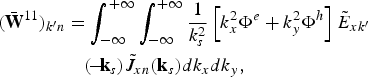 $$\eqalign{ {\lpar {\bar {\bf W} ^{11}}\rpar _{{k^{\prime}}n}}& = \int_{ - \infty }^{ + \infty } {\int_{ - \infty }^{ + \infty } {\displaystyle{1 \over {k_s^2 }}\left[{k_x^2 {\Phi ^e} + k_y^2 {\Phi ^h}} \right]{{\tilde E}_{x{k^{\prime}}}}} } \cr & \quad \lpar\! -\! {{\bf k}_s}\rpar {{\tilde J}_{xn}}\lpar {{\bf k}_s}\rpar d{k_x}d{k_y}\comma \; }$$
 $$\eqalign{& {\lpar {\bar {\bf W} ^{12}}\rpar _{{k^{\prime}}m}} = \int_{ - \infty }^{ + \infty } {\int_{ - \infty }^{ + \infty } {\displaystyle{{{k_x}{k_y}} \over {k_s^2 }}\left[{{\Phi ^e} - {\Phi ^h}} \right]{{\tilde E}_{x{k^{\prime}}}}} } \lpar \!- \!{{\bf k}_s}\rpar {{\tilde J}_{ym}}\lpar {{\bf k}_s}\rpar d{k_x}d{k_y}\comma \; }$$
 $$\eqalign{& {\lpar {\bar {\bf W} ^{21}}\rpar _{{l^{\prime}}p}} = \int_{ - \infty }^{ + \infty } {\int_{ - \infty }^{ + \infty } {\displaystyle{{{k_s}{k_y}} \over {k_s^2 }}\left[{{\Phi ^e} - {\Phi ^h}} \right]{{\tilde J}_{y{l^{\prime}}}}} } \lpar \!-\! {{\bf k}_s}\rpar {{\tilde J}_{xn}}\lpar {{\bf k}_s}\rpar d{k_x}d{k_y}\comma \; }$$
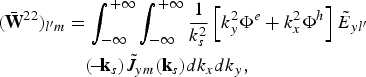 $$\eqalign{ {\lpar {\bar {\bf W} ^{22}}\rpar _{{l^{\prime}}m}}& = \int_{ - \infty }^{ + \infty } {\int_{ - \infty }^{ + \infty } {\displaystyle{1 \over {k_s^2 }}\left[{k_y^2 {\Phi ^e} + k_x^2 {\Phi ^h}} \right]{{\tilde E}_{y{l^{\prime}}}}} } \cr & \quad \lpar \!-\! {{\bf k}_s}\rpar {{\tilde J}_{ym}}\lpar {{\bf k}_s}\rpar d{k_x}d{k_y}\comma \; }$$
Finally, the elements of the matrix  ${\lpar \bar{\bf Z}\rpar _{\lpar P+Q\rpar \times \lpar P+Q\rpar }}$ are given by
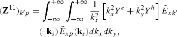 $$\eqalign{ {\lpar {\bar {\bf Z} ^{11}}\rpar _{{k^{\prime}}p}} &= \int_{ - \infty }^{ + \infty } {\int_{ - \infty }^{ + \infty } {\displaystyle{1 \over {k_s^2 }}\left[{k_x^2 {Y^e} + k_y^2 {Y^h}} \right]{{\tilde E}_{x{k^{\prime}}}}} } \cr & \quad \lpar \!-\! {{\bf k}_s}\rpar {{\tilde E}_{xp}}\lpar {{\bf k}_s}\rpar d{k_x}d{k_y}\comma \; }$$
 $$\eqalign{& {\lpar {\bar {\bf Z} ^{12}}\rpar _{{k^{\prime}}q}} = \int_{ - \infty }^{ + \infty } {\int_{ - \infty }^{ + \infty } {\displaystyle{{{k_x}{k_y}} \over {k_s^2 }}\left[{{Y^e} - {Y^h}} \right]{{\tilde E}_{x{k^{\prime}}}}} } \lpar \!- \!{{\bf k}_s}\rpar {{\tilde E}_{yq}}\lpar {{\bf k}_s}\rpar d{k_x}d{k_y}\comma \; }$$
 $$\eqalign{& {\lpar {\bar {\bf Z} ^{21}}\rpar _{{l^{\prime}}p}} = \int_{ - \infty }^{ + \infty } {\int_{ - \infty }^{ + \infty } {\displaystyle{{{k_s}{k_y}} \over {k_s^2 }}\left[{{Y^e} - {Y^h}} \right]{{\tilde E}_{y{l^{\prime}}}}} } \lpar\! -\! {{\bf k}_s}\rpar {{\tilde E}_{xp}}\lpar {{\bf k}_s}\rpar d{k_x}d{k_y}\comma \; }$$
 $$\eqalign{& {\lpar {\bar {\bf Z} ^{22}}\rpar _{{l^{\prime}}q}} = \int_{ - \infty }^{ + \infty } {\int_{ - \infty }^{ + \infty } {\displaystyle{1 \over {k_s^2 }}\left[{k_y^2 {Y^e} + k_x^2 {Y^h}} \right]{{\tilde E}_{y{l^{\prime}}}}} } \lpar \!-\! {{\bf k}_s}\rpar {{\tilde E}_{yq}}\lpar {{\bf k}_s}\rpar d{k_x}d{k_y}.}$$
Appendix B
To make the theoretical formulation more general and valid for various antennas structures (not only limited to single microstrip patch), the metallic patch is assumed to be embedded in a multilayered media consisting of N substrates with the optical axis normal to the patch (see Fig. 1 in [Reference Fortaki and Benghalia13]).
Once the complex resonance frequency is known, the eigenvector corresponding to the minimum eigenvalue of the matrix gives the coefficients of the current on the conductor patch and those of the electric field at the aperture on the ground plane. The method of stationary phase makes it possible to obtain the following interface radiated in the upper half-space air of Fig. 1 in terms of the transverse electric field:
 $$\left[{\matrix{ {{E_{\theta ^{\prime}}}\lpar r^{\prime}\comma \; \theta ^{\prime}\comma \; \varphi ^{\prime}\rpar } \cr {{E_{\varphi ^{\prime}}}\lpar r^{\prime}\comma \; \theta ^{\prime}\comma \; \varphi ^{\prime}\rpar } \cr } } \right]=i{k_0}\displaystyle{{{e^{ - i{k_0}r^{\prime}}}} \over {2\pi r^{\prime}}}\left[{\matrix{ { - 1} & 0 \cr 0 & {\cos\! \theta ^{\prime}} \cr } } \right]\cdot {\bf e}\lpar {{\bf k}_s}\comma \; {z_N}\rpar \comma \;$$
where a local spherical coordinate system defined relative to the Cartesian {x′ ≡ x, y′ ≡ y, z′ ≡ z} system having an origin placed at the interface z = z N of Fig. 1 [Reference Fortaki and Benghalia13].
From equations (12 and 13 in [Reference Fortaki and Benghalia13]), we can obtain the transverse electric field e(ks, z N) at the interface z = z N as a function of the transverse electric field e(ks, z P) to the interface z = z P as follows [Reference Fortaki and Benghalia13]:
 $${\bf e}\lpar {{\bf k}_s}\comma \; {z_N}\rpar ={\left[{{{\bar{\bf \Gamma}}_\gt }^{22} - {{\bar{\bf g}}_0}.{{\bar{\bf \Gamma}}_\gt }^{12} } \right]^{^{ - 1} }} \cdot {\bf e}\lpar {{\bf k}_s}\comma \; {z_P}\rpar.$$
Taking into account (4.14) in [Reference Fortaki and Benghalia13] and (B.2), equation (B.1) becomes
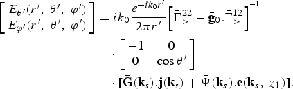 $$\eqalign{\left[{\matrix{ {{E_{\theta ^{\prime}}}\lpar r^{\prime}\comma \; \theta ^{\prime}\comma \; \varphi ^{\prime}\rpar } \cr {{E_{\varphi ^{\prime}}}\lpar r^{\prime}\comma \; \theta ^{\prime}\comma \; \varphi ^{\prime}\rpar } \cr } } \right]& =i{k_0}\displaystyle{{{e^{ - i{k_0}r^{\prime}}}} \over {2\pi r^{\prime}}}{\left[{{{\bar{\bf \Gamma}}_\gt }^{22} - {{\bar{\bf g}}_0}.{{\bar{\bf \Gamma}}_\gt }^{12} } \right]^{^{ - 1} }} \cr &\quad\cdot \left[{\matrix{ { - 1} & 0 \cr 0 & {\cos \theta ^{\prime}} \cr } } \right]\cr &\quad \cdot \lsqb \bar{\bf G}\lpar {{\bf k}_s}\rpar .{\bf j}\lpar {{\bf k}_s}\rpar +\bar{\bf \Psi}\lpar {{\bf k}_s}\rpar .{\bf e}\lpar {{\bf k}_s}\comma \; {z_1}\rpar \rsqb .}$$
In equations (B.1) and (B.3), (k x, k y) are the points given by the stationary phase
 $${k_x}=- {k_0}\sin\! \theta ^{\prime}\cos\! \varphi ^{\prime}\comma \;$$
 $${k_y}=- {k_0}\sin\! \theta ^{\prime}\sin\! \varphi ^{\prime}.$$
Unlike the method in which the equivalent limit the radiated field is calculated via recurrent formulas [Reference Losada, Boix and Horno29], the expression (B.3) allows the calculation of the radiated field in the upper half-space of the air in Fig. 1 using simple matrix multiplications.
Still based on the technique of the stationary phase, the radiated in the lower half-space air of Fig. 1 field can be obtained in terms of the transverse electric field at the interface z = 0 as follows:
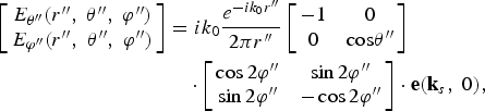 $$\eqalign{ \left[{\matrix{ {{E_{\theta ^{\prime \prime}}}\lpar r^{\prime \prime}\comma \; \theta ^{\prime \prime}\comma \; \varphi ^{\prime \prime}\rpar } \cr {{E_{\varphi ^{\prime \prime}}}\lpar r^{\prime \prime}\comma \; \theta ^{\prime \prime}\comma \; \varphi ^{\prime \prime}\rpar } \cr } } \right] & =i{k_0}\displaystyle{{{e^{ - i{k_0}r^{\prime \prime}}}} \over {2\pi r^{\prime \prime}}}\left[{\matrix{ { - 1} & 0 \cr 0 & {\cos\! \theta ^{\prime \prime}} \cr } } \right]\cr &\quad\cdot \left[{\matrix{ {\cos 2\varphi ^{\prime \prime}} & {\sin 2\varphi ^{\prime \prime}} \cr {\sin 2\varphi ^{\prime \prime}} & { - \cos 2\varphi ^{\prime \prime}} \cr } } \right] \cdot {\bf e}\lpar {{\bf k}_s}\comma \; 0\rpar \comma \; }$$
where {r″, θ″, ϕ″} a local spherical coordinate system defined relative to the Cartesian {x″ ≡ x, y″ ≡ −y, z″ ≡ −z} system having an origin placed at the interface of Fig. 1.
From equations ((10) and (16) in [Reference Fortaki and Benghalia13]), we can obtain the transverse electric field e(ks, 0) at the interface z = 0 as a function of the e(ks, z 1) transverse electric field to the interface z = z 1 as follows:
 $${\bf e}\lpar {{\bf k}_s}\comma \; 0\rpar ={\left[{{{\bar{\bf T}}_1}^{11} - {{\bar{\bf g}}_0} .{{\bar{\bf T}}_1}^{12} } \right]^{^{ - 1} }} \cdot {\bf e}\lpar {{\bf k}_s}\comma \; {z_1}\rpar.$$
Substituting (B.5) into (B.6), equation (B.6) becomes
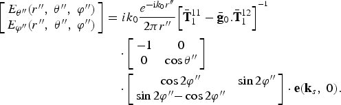 $$\eqalign{ \left[{\matrix{ {{E_{\theta ^{\prime \prime}}}\lpar r^{\prime \prime}\comma \; \theta ^{\prime \prime}\comma \; \varphi ^{\prime \prime}\rpar } \cr {{E_{\varphi ^{\prime \prime}}}\lpar r^{\prime \prime}\comma \; \theta ^{\prime \prime}\comma \; \varphi ^{\prime \prime}\rpar } \cr } } \right]& =i{k_0}\displaystyle{{{e^{ - {\rm i}{k_0}r^{\prime \prime}}}} \over {2\pi r^{\prime \prime}}}{\left[{{{\bar{\bf T}}_1}^{11} - {{\bar{\bf g}}_0} .{{\bar{\bf T}}_1}^{12} } \right]^{^{ - 1} }} \cr & \quad \cdot \left[{\matrix{ { - 1} & 0 \cr 0 & {\cos \theta ^{\prime \prime}} \cr } } \right]\cr &\quad\cdot \left[{\matrix{ {\cos 2\varphi ^{\prime \prime}} & {\sin 2\varphi ^{\prime \prime}} \cr {\sin 2\varphi ^{\prime \prime}} { - \cos 2\varphi ^{\prime \prime}} \cr } } \right]\cdot {\bf e}\lpar {{\bf k}_s}\comma \; 0\rpar .}$$
In equations (B.6) and (B.7), (k x, k y) are the points given by the stationary phase
 $${k_x}=- {k_0}\sin \theta ^{\prime \prime}\cos \varphi ^{\prime \prime}\comma \;$$
 $${k_y}=- {k_0}\sin \theta ^{\prime \prime}\sin \varphi ^{\prime \prime}.$$
Lotfi Djouane was born in Batna, Algeria, in 1980. He received his Master Science and Ph.D. degrees in Electronics Engineering from the University of Batna, Algeria, in 2006 and 2009, respectively. Currently, he is an Associate Professor in the Department of Electronics at M'sila University, Algeria. He has published five papers in refereed journals and more than ten papers in conference proceedings. His main research deals with numerical methods and microstrip antennas.
Sami Bedra was born on August 3, 1984 in Batna, Algeria. He obtained his Engineer and Master Science degrees both in Electronics from the University of Batna, Algeria, in 2008 and 2011, respectively. He is currently working toward the Ph.D. degree at the University of Batna. His current research activities include neural network, optimization techniques, and their applications to patch antennas.
Randa Bedra was born on September 9, 1989 in Batna, Algeria. She received her Master Science in Microwave and Telecommunications from the University of Batna, Algeria, in 2013. She is currently with the Laboratory of Advanced Electronics at the Electronics Department, University of Batna, Batna, Algeria. She is currently working toward the Ph.D. degree at the University of Batna. Her main research deals with numerical methods and microstrip antennas.
Tarek Fortaki was born on March 31, 1972 in Constantine, Algeria. He received his Engineer of Communication degree in 1995, the Master Science degree in Microwaves in 1999, and the Doctorate degree in Microwaves in 2004, all from the Electronics Department, Faculty of Engineering Science, University of Constantine. Currently, he is a Professor at the Electronics Department, Faculty of Engineering Science, University of Batna. He has published 17 papers in refereed journals and more than 40 papers in conference proceedings. He serves as reviewer for several technical journals. His main interests are electromagnetic theory, numerical methods and modeling of antennas, and passive microwave circuits.