I. INTRODUCTION
Semiconductor photocatalysis technology (TiO2 and ZnO were mainly used as photocatalysts) has attracted much attention in the last decade because of their potential application in the environmental remediation. Reference Asl, Sadrnezhaad and Kianpourrad1–Reference Nahar, Hasegawa and Kagaya7 Typically, the photocatalytic process for treatment of wastewater is carried out in a suspended slurry system owing to its unique advantages including: (i) high specific area, (ii) the efficient solar utilization, and (iii) fast mass transfer of pollutants from aqueous medium to surface of semiconductor powder. Reference Mukherjee and Ray8–Reference Liu10 However, the recovery and cyclic utilization of photocatalyst are still major obstacle, which hindered their practical application because the small particles are easily discharged in waters. To overcome the drawback of suspended slurry system, various kinds of immobilized photocatalyst have been used in a fixed bed, such as TiO2-based thin film Reference Kominami, Kumamoto, Kera and Ohtani11,Reference Arabatzis, Antonaraki, Stergiopoulos, Hiskia, Papaconstantinou, Bernard and Falaras12 and the immobilization of photocatalyst on easily recoverable materials (including glass beads Reference Jackson, Wang, Luo, Schwitzgebel, Ekerdt, Brock and Heller13 , ceramic plates Reference Bideau, Claudel, Dubien, Faure and Kazouan14 , fiberglass Reference Pozzo, Baltanas and Cassano15,Reference Horikoshi, Watanabe, Onishi, Hidaka and Serpone16 and zeolite Reference Anpo, Shu, Mishima, Matsuoka and Yamashita17 ). However, the immobilization of photocatalysts can decrease their photocatalytic activity because the specific area, solar utilization, and mass transfer are limited by the supports.
Therefore, it is necessary to develop photocatalysts possessed separable function for the reusable and cyclic applications, as well as retain the advantage of the high activity of suspended slurry system. In this background, some environmental scientists combined magnetic particles with semiconductor photocatalysts to achieve above purpose. Reference Pang, Li, Guan, Lu and Gao18–Reference Gao, Chen, Li and Ma23 The magnetic photocatalysts are desired because they have the advantage of suspended slurry system and magnetic separation characteristics. Initially, the as-obtained magnetic photocatalysts were composed of two components: a magnetic core with magnetic separation function and a semiconductor shell with photocatalytic function, such as Fe3O4/TiO2, Reference Beydoun, Amal, Low and McEvoy19 BaFe2O4/TiO2, Reference Lee, Drwiega, Wu, Mazyck and Sigmund24 NiFe2O4/TiO2, Reference Rana and Misra25 SrFe12O19/TiO2, Reference Fu, Yang, Chang, Li, Hari-Bala and Zou26 BaFe12O19/TiO2, Reference Fu, Yang, Li, Chang, Yu, Xu and Zou27 and Fe3O4/BiOCl. Reference Zhang, Wang, Zhou, Shang and Sun28 However, the direct contact between magnetic core and semiconductor photocatalyst usually gave rise to an unfavorable heterojunction, which caused the recombination of photogenerated electron–hole pairs and the photodissolution of the magnetic particles under the irradiation. Reference Beydoun, Amal, Low and McEvoy19 To overcome the above drawbacks, it is necessary to introduce an interlayer as insulator between magnetic core and photocatalyst shell. Silica is one of the most effective interlayer materials for insulation in the preparation of the magnetic photocatalysts. Reference Yu, Liu and Yu29–Reference Wang, Ao, Wang, Hou and Qian32 In these studies, magnetically recoverable photocatalysts were usually obtained by a sol–gel method, where the following heat-treatment is essential. Thus, it resulted in loss of magnetic property due to phase transition of magnetic core, and that the synthetic processes are also very complicated.
From the application point of view, the facility of the synthetic processes of photocatalyst is necessary and important. Therefore, how to realize easy synthesis of recoverable photocatalyst is still one of the challenges for the materials scientists. Herein, the decoration of metallic Ni as a new strategy was presented to obtain magnetically recoverable ZnO photocatalyst with good stability and high photocatalytic reactivity. To obtain the magnetically recoverable photocatalyst, this strategy has obvious advantages as compared to conventional approaches: (i) to avoid the use of interlayer in photocatalysts with core–shell structure and (ii) beneficial metal Ni/ZnO heterostructure can be formed. The Ni-decorated ZnO photocatalysts with excellent magnetic recoverability were synthesized via a simple replacing-hydrothermal route using Zn powder and NiCl2 as raw materials. It is found that the Ni-decorated ZnO composites exhibit excellent photoactivity and strong magnetic property, which can be ascribed to the incorporation of metallic Ni into the composites.
II. EXPERIMENTAL DETAILS
A. Reagents and materials
Pure Zn powder, nickel chloride (NiCl2), hydrochloric acid (HCl), and reactive brilliant blue KN-R were purchased from Tianjin Chemical Reagents Company. All these reagents were of analytical grade and were used without further purification in all experiments.
B. Synthesis of samples
Synthesis of Ni-decorated ZnO composites: pure Zn powder, NiCl2, and deionized water were used as raw materials. Zinc powder (1.5 g) was added into 100 mL NiCl2 aqueous solution with desired concentration under magnetic stirring at 60 °C for 2 h [In this process, Ni2+ was reduced to Ni0 by Zn powder, meanwhile the green color of solution disappeared. No trace of nickel ions was detected by atomic absorption spectrometry (AAS) analysis in this solution, which indicated that the Ni2+ was completely reduced to Ni0 (see Supplementary Materials)]. The as-obtained solid product and 35 mL deionized water were loaded into a 50 mL Teflon-lined stainless steel autoclave and sealed tightly. Hydrothermal treatments were carried out at 180 °C for 2 h. After that, the autoclave was allowed to cool down naturally. Precipitates were collected and washed with deionized water several times and dried at 80 °C. For comparison, pure ZnO as a reference was also prepared by the same hydrothermal process with synthesis of Ni-decorated ZnO composites, only NiCl2 is absent in this process.
C. Characterization of samples
The products were characterized by x-ray powder diffraction on a Shimadzu XRD-6100 x-ray diffractometer (Kyoto, Japan) with a graphite-monochromatized Cu Kα radiation (λ = 1.5418 Å). UV–visible diffuse reflectance spectra were recorded on a Varian Cary-100 spectrophotometer by using BaSO4 as a reference material. The surface structure of the as-prepared samples was determined by x-ray photoelectron spectroscopy (XPS) and was performed using a VG EscaLab 250 SYSTEM (Thermo VG) with Al Kα radiation (1486.6 eV). The C1s photoelectron peak (binding energy at 284.6 eV) was used as an energy reference. The magnetic study with applied magnetic field is done using a vibrating sample magnetometer (VSM, JDM-13, Jilin University, Wuhua Application Technology Development Co.). Morphology and particle sizes were analyzed on a JSM-6460LV (JEOL, Tokyo, Japan) scanning electron microscope (SEM). Samples for transmission electron microscopy (TEM) were prepared by placing a droplet of the suspension of photocatalysts onto a copper grid and allowing the solvent to evaporate. The TEM images were obtained on a FEI TECNAI G2 F20 microscope (Portland, OR) at an accelerating voltage of 200 kV. Energy dispersive x-ray spectroscopy (EDX) analysis was performed during TEM measurements. The photoelectrochemical measurements were performed on a standard three-electrode system using the prepared samples as the working electrodes, a platinum foil as a counter electrode, and Ag/AgCl electrode as a reference electrode. The electrode potential and working current are controlled by an electrochemical analyzer (CHI660D Instruments). The working electrodes were prepared as follows: 0.05 g of the sample was grinded with 0.1 g terpinol to make a slurry, which was then dip-coated onto a 2 cm × 1 cm indium tin oxide-coated glass electrode. Next, these electrodes were dried at 120 °C for 30 min under N2 flow. All investigated electrodes have a similar film thickness. Photocurrent response was detected by linear sweep voltammetry (LSV) in the 0.2 M Na2SO4 solution using a 300 W xenon lamp as light source.
D. Test of photocatalytic activity
The photocatalytic activities of the samples were evaluated by the degradation of anthraquinone dye (reactive brilliant blue KN-R) in an aqueous solution. 200 mL anthraquinone dye aqueous solution with a concentration of 20 mg/L was mixed with 20 mg/L catalyst, which was exposed to illumination of 300 W xenon lamp (as simulated sunlight source). Before turning on the lamp, the suspensions containing reactive brilliant blue KN-R and photocatalyst were magnetically stirred under a dark condition for 30 min till an adsorption–desorption equilibrium was established. Samples were then taken out regularly from the reactor and centrifuged immediately for the separation of any suspended solid. The absorbance A of transparent solution was measured by a 721B spectrophotometer, and the A value was used to estimate the photocatalytic degradation rate D of reactive brilliant blue K-NR according to the equation:
 $$D = {{\left( {{A_0} - {A_t}} \right)} \mathord{\left/ {\vphantom {{\left( {{A_0} - {A_t}} \right)} {{A_0}}}} \right. \kern-\nulldelimiterspace} {{A_0}}} \times 100\% \quad ,$$
where A 0 is the initial absorbance of reactive brilliant blue K-NR, t is the reaction time, and A t is the absorbance at time t.
In recycled photodegradation experiments, the photocatalyst was re-collected by external magnetic field, and the detailed procedure is as follows: after completion of a previous photodegradation run, the stirring of suspension was stopped and standing until catalyst particles was attracted to the surface of external magnet, which clung to a container wall (placing of external magnet is carried out after stopping stir), then the solution was emptied by the outlet of the container.
III. RESULTS AND DISCUSSION
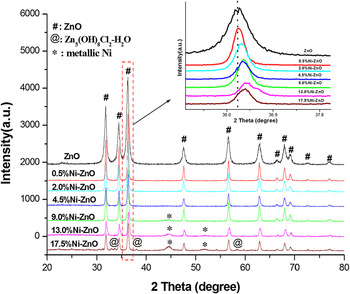
The x-ray diffraction (XRD) patterns of samples with different Ni loadings are shown in Fig. 1. It can be seen that the ZnO (JCPDS Card no. 36-1451) was found in XRD spectra of all samples, and no metallic Zn phase was found. This result suggested that metallic Zn converted entirely to ZnO under hydrothermal conditions. Furthermore, when the content of Ni is less than 4.5 at.% [Ni/(Ni + Zn) atomic ratio], no trace of nickel species was observed in these samples. However, Ni loadings reached 9.0 at.%, the diffraction peaks of metallic Ni (JCPDS Card no.65-2865) were observed. It is noteworthy that the absence of Ni2+ species in XRD patterns may be attributed to the fact that the Ni ions were highly dispersed in the ZnO matrix (Ni ions may be incorporated into the lattice of ZnO and substituting for Zn2+). Meanwhile, the impurity peaks corresponding to Simonkolleite [Zn5(OH)8Cl2∙H2O, JCPDS Card no. 07-0155] were detected in Ni–ZnO samples with high Ni loadings, which can be ascribed to remaining Cl−.
XRD patterns of the as-synthesized samples: Zn powder with various Ni loadings after hydrothermal treatment at 180 °C for 2 h.

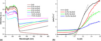
Although introduction of nickel does not change the structure of wurtzite ZnO, whereas the centers of all diffraction peaks have a slight shift toward higher Bragg angle as compared to that of pure ZnO (see Fig. 1, insets). This shift toward higher Bragg angle suggests that the Zn atoms in the lattice of ZnO crystals may be substituted by Ni atom because the atomic radius of Ni (0.69 Å) is less than that of Zn (0.74 Å). Similar results were also reported in earlier studies. Reference Singh, Rama and Ramachandra Rao33–Reference Cheng, Xiao, Wu and Zhang36 The optical absorption spectra have been used as a probe for understanding the excitation processes of the Ni-decorated ZnO composites. It can be seen from Fig. 2(a) that the pure ZnO and Ni-decorated ZnO samples have strong absorption bands below 400 nm, which was ascribed to intrinsic gap between the valence band and the lower-lying conduction band. The Ni-decorated ZnO samples showed obvious absorption in the longer wave length range (>400 nm). This may be ascribed to the absorption of the metallic Ni, which is usually observed for metal/metal oxide composites. Reference Pal, Garcia-Serrano, Casarrubias-Segura, Koshizaki, Sasaki and Terahuchi37 Furthermore, it can be seen from Fig. 2(b) that Ni-decorated ZnO composites showed obvious red shift as compared to that of pure ZnO. The red shift of the band gap absorption edge for Ni-decorated ZnO composites can be associated with the sp–d exchange interactions between the conduction band electrons and the localized d electrons of the transition metal-ions, which substitute the Zn2+ ions. Reference Xu, Cao, Su, Liu, Qu and Yu38 Thus, the shift of band edge toward higher wave length side for Ni-decorated ZnO composites indicated that the Ni ions were introduced into the ZnO lattice.
UV–visible diffuse reflectance spectra of the as-synthesized samples.

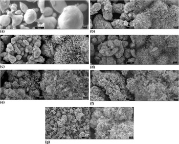
The morphologies of the Zn powder and as-synthesized samples were characterized by SEM and are shown in Figs. 3(a)–3(g). As can be seen from Fig. 3(a), the original morphology of the Zn powder is irregular spherical-like particles with smooth surfaces, and its size range is from 1 to 10 μm. SEM images of ZnO reference are shown in Fig. 3(b). ZnO reference exhibited urchin-like three-dimensional (3D) microstructures. It is noteworthy that introduction of Ni changed significantly the aspect of the ZnO microstructures. When Zn powder etched by a small amount of Ni2+ (Ni/Zn ratio is 2.0 and 4.5 at.%), the fairly uniform urchin-like microstructures assembled by well-aligned nanorod arrays are observed as shown in Figs. 3(c) and 3(d). However, the increase of Ni content resulted in collapse of ZnO 3D-microstructures, and morphology of ZnO gradually turned from nanorods to prism and sheet-like particles [see Figs. 3(e)–3(g)].
SEM images of samples: (a) metallic Zn powder; (b) as-obtained ZnO; and (c–g) Ni-decorated ZnO with Ni loadings of 2.0%, 4.5%, 9.0%, 13.0%, and 17.5%, respectively.

According to earlier reports, Reference Sun, Chen, Deng and Li39–Reference Srivastava, Tiwari, Srivastava, Porwal and Deb42 the possible formation process of ZnO under hydrothermal conditions can be divided into two stages for reaction and crystal growth. In the first stage, active Zn atoms located at the surface of zinc particle reacted with water to form zinc ions, OH−, and hydrogen. As a result, the concentration of zinc ions and OH− around the zinc particles increased and Zn(OH)2 or Zn(OH)4 2− is then formed in situ via the reaction of Zn2+ and OH−. Reference Li, Shi, Zhong and Yin43,Reference Wang, Shi and Zhong44 In the crystal-growth stage, ZnO gradually nucleated and grew spontaneously by dehydration of Zn(OH)2 or Zn(OH)4 2− under hydrothermal conditions. The two stages can be expressed by the following reaction:
 $${\rm{Zn}} + {{\rm{H}}_2}{\rm{O}} \to {\rm{Z}}{{\rm{n}}^{2 + }} + {{\rm{H}}_2} \uparrow + {\rm{O}}{{\rm{H}}^ - }\quad ,$$
 $${\rm{Z}}{{\rm{n}}^{2 + }} + {\rm{O}}{{\rm{H}}^ - } \to \left\{ {{\rm{Zn}}\left( {{\rm{OH}}} \right)_4^{2 - }\;{\rm{or}}\;{\rm{Zn}}{{\left( {{\rm{OH}}} \right)}_2}} \right\} \to {\rm{ZnO}} + {{\rm{H}}_2}{\rm{O}}\quad {\rm{.}}$$
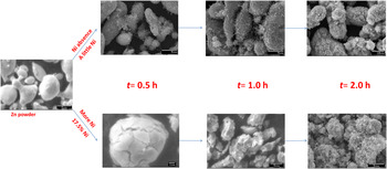
To understand more on the effect of introducing Ni on the morphologies of the ZnO microstructures, the kinetic analysis of crystal growth was performed under our experimental conditions. As shown in Fig. 4, a few ZnO nanorods anchored on the surface of Zn sphere under initial hydrothermal stage. As the time prolonged, the ZnO nanorods gradually grow and become denser. Finally, the nanorod array microstructures formed under hydrothermal conditions. We consider that the closeness of crystallographic parameters between Zn and ZnO probably facilitated nucleation and anchoring of as-formed ZnO precursor. Furthermore, the contact potential difference (1.5 V) at (Zn)/(ZnO) boundary Reference Fomenko45 may also improve growth of nanorods and nanowhiskers. Reference Vostrikov, Fedyaeva, Shishkin and Sokol41 However, a different evolution process of morphologies from Zn powder to ZnO was observed by SEM under initial hydrothermal stage when Ni content is higher. In that case, the morphology of Zn powder gradually crushed and turned to prism and sheet-like particles as hydrothermal treating prolonged. It can be attributed to the fact that the as-formed metallic Ni layer around the zinc cores would cover the active sites at the surface of zinc particle and thus prevents the nucleation and anchoring of the as-formed ZnO precursor on the surface of Zn particle and makes obvious inside erosion. Moreover, we consider that the substitution of Ni ion in as-formed ZnO crystals may control the growth rate of different crystal faces, which resulted in the formation of prism and sheet-like ZnO crystals.
Hydrothermal kinetic analysis of crystal growth for Zn with and without Ni.

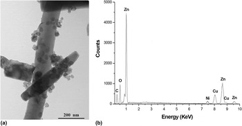
The microstructure of the Ni-decorated ZnO sample was characterized by TEM, and the results are shown in Fig. 5. A TEM image of the Ni-decorated ZnO sample (9.0 at.% Ni–ZnO) is presented in Fig. 5(a). It can be seen that some nanoparticles were randomly dispersed on the surface of the rod-like ZnO crystals, and the average size of the nanoparticles is estimated to be about 40 nm. Figure 5(b) shows the EDX spectrum from Fig. 5(a), and it implied that the Ni-decorated ZnO microstructures are composed of Zn, Ni, and O, which is consistent with the XRD results [notice that copper signal in Fig. 5(b) comes from the copper grid on which the Ni–ZnO composites were mounted]. Furthermore, the TEM image of the ZnO reference showed that the surface of rod-like ZnO reference is clean (there is no nanoparticles), which obviously differed from that of Ni-decorated ZnO (see Fig. S1 in Supplementary Materials). Based on the above results, these 40 nm particles on the surface of Ni-decorated ZnO can be regarded as a cluster of Ni metal. Considering the presence of metal Ni nanoclusters on the surface of ZnO, a great amount of metal–semiconductor interfaces may be constructed in the Ni-decorated ZnO composites. Thus, these metal–semiconductor heterojunctions could facilitate the charge transfer and hence improved the photocatalysis efficiency.
(a) TEM image and (b) EDX spectra of Ni-decorated ZnO photocatalyst with 9.0% Ni loading.

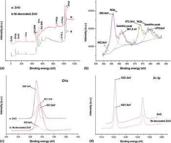
XPS was used to probe the surface properties of the as-synthesized samples. The survey spectra of ZnO reference and Ni-decorated ZnO samples are shown in Fig. 6(a). A detectable Ni2p peak could be observed in the Ni-decorated ZnO sample as compared to that of ZnO reference, which confirmed that the Ni was successfully introduced into the ZnO. The high-resolution XPS spectra of Ni2p3/2 and Ni2p1/2 core levels and their satellites peaks are shown in Fig. 6(b). The Ni2p3/2 peak can be deconvoluted into both peaks at binding energies of 852.9 and 855.8 eV, respectively. The Ni2p3/2 peak located at around 852.9 eV can be assigned to metal Ni. Reference Prieto, Nistor, Nouneh, Oyama, Abd-Lefdil and Díaz46–Reference Moulder, Stickle, Sobol and Bomben48 Other Ni2p3/2 peak located at 855.8 eV, which is quite different from that of NiO (853.8 eV) and Ni2O3 (856.7 eV). Reference Roberts and Smart47–Reference Moroney, Smart and Roberts52 Moreover, the corresponding energy difference between the Ni2p3/2 and Ni2p1/2 peaks is about 17.5 eV. These XPS results are comparable to the results presented in the literature, Reference Iqbal, Wang, Liu, Yu, He and Yu53–Reference Dar, Agrawal and Sen55 which indicated that Ni ions with a valence of +2 are successfully substituted into Zn site of the ZnO lattice. The Ni substitution for Zn site in ZnO matrix is also confirmed by XRD and UV–vis results mentioned above. Furthermore, the amount of Ni2+ on the surface of all samples is more than that of Ni0 according to XPS analysis, which is not in agreement with the above XRD results (no diffraction peaks of Ni2+ species can be observed in XRD patterns). This is reasonable because XPS is a surface-sensitive technique, while XRD is a bulk characterization technique.
XPS spectra of the as-synthesized samples prepared by hydrothermal treatment (a) XPS survey spectra of samples; (b) The Ni2p XPS spectra of 9.0% Ni-decorated ZnO composite; (c) the fitted O1s XPS spectra of the as-synthesized samples; and (d) the Zn2p XPS spectra of the as-synthesized samples.

Figure 6(c) shows the O1s XPS peak of Ni-decorated ZnO sample. The XPS peak of O1s can be fitted into two kinds of oxygen species by Gaussian method. They can be attributed to the fact that the crystal lattice oxygen is centered at around 530.25 ± 0.15 and adsorbed oxygen (chemically and physically) is centered at around 531.15 ± 0.05 eV, Reference Marta56,Reference Fujishima, N.Rao and Tryk57 respectively. It can be seen that the introduction of Ni made the position of O1s XPS peak shifted to higher binding energy, and the relative amount of adsorbed oxygen for Ni-decorated ZnO is more, as compared to that of pure ZnO. The abundant adsorbed oxygen (as the electronic scavenges) is favorable for the improvement of photocatalytic activity because it inhibited the recombination of photoexcited electron–hole pairs. Similar result was also observed in the study on the surface modification of ZnO by depositing Pd. Reference Jing, Wang, Xin, Li, Shi, Cai and Fu58 In addition, the binding energies of Zn2p3/2 for ZnO reference and Ni-decorated ZnO are shown in Fig. 6(d). It is noteworthy that introduction of Ni shifted the binding energy of Zn2p3/2 to a higher energy (1021.5 eV), as compared with that of ZnO reference (1021.2 eV). This shift of Zn2p3/2 peak may be ascribed to the reduction of the surface band bending and the introduction of Ni ions into ZnO matrix.
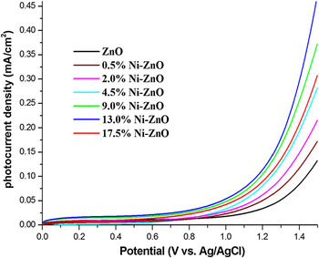
The photoelectrochemical measurement of samples is carried out in 0.2 M Na2SO4 solution. The LSV photocurrent response of different photocatalysts (see Fig. 7) was obtained from the difference between the corresponding polarization currents of catalyst under illumination and dark. The value of the photocurrent can reflect the ability of separation and transfer of photogenerated charge carried out in photocatalysts. Reference Kim, Borse, Choi and Lee59 It can be seen from Fig. 7 that the Ni-decorated ZnO composites exhibited a higher photocurrent density than that of ZnO reference under the same anodic potential. This means that the Ni-decorated ZnO composites have improved separation and transfer efficiency of photogenerated charges, as compared to that of ZnO reference.
Photocurrent–voltage characteristics of the obtained photocatalysts.

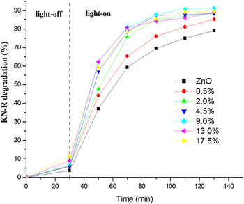
The photocatalytic activities of the as-synthesized samples are shown in Fig. 8. It can be seen from Fig. 8 that all of the Ni-decorated ZnO composites showed higher photocatalytic activity than that of ZnO reference. Obviously, the Ni decoration is a key factor to improve the photocatalytic activity of ZnO. Based on the above experimental results, the improvement of photocatalytic activity for Ni-decorated ZnO composites may be ascribed to the following causes: (i) the transition metal-ions (Ni2+) can easily penetrate into the ZnO crystal lattice or substitute the Zn2+ position in the crystal and act as a deep acceptor in combination with a neighboring O vacancy, Reference Donkova, Dimitrov, Kostadinov, Mitkova and Mehandjiev60,Reference Kanai61 substantially improves the electrical transport of photoinduced charges and light absorption; (ii) metal clusters (metal Ni) act as electron sinks and inhibit the recombination of photoinduced electron–hole pairs due to the formation of metal–semiconductor heterojunctions Reference Ma, Teng, Fu, Song, Wang and Dong62–Reference Li and Li64 ; and (iii) the abundant adsorbed oxygen (as the electronic scavenges), which improved the separation of photoexcited electron–hole pairs. Reference Jing, Wang, Xin, Li, Shi, Cai and Fu58,Reference Ma, Teng, Fu, Song, Wang and Dong62 It is noteworthy that the photocatalytic degradation rate of KN-R over the as-synthesized samples is not perfectly consistent with the above UV–vis absorption and photocurrent results. It is well-known that the photocatalytic activity of the catalyst was governed by various factors, such as ability of light absorption, transportation of photogenerated carriers, and surface reaction process. Thus, the inconsistency between UV–vis absorption intensities (or photocurrent) and photocatalytic activities of the samples might result from the combined action including light absorption, photogenerated carriers transportation, and surface reaction process. Furthermore, to confirm the effect of Zn5(OH)8Cl2∙H2O on photocatalytic activity of Ni-decorated ZnO, the comparison of photocatalytic activity for pure Zn5(OH)8Cl2∙H2O and 17.5% Ni-decorated ZnO without or with Zn5(OH)8Cl2∙H2O impurities was performed (see Fig. S2–S3 in Supplementary Materials). It is found that the pure Zn5(OH)8Cl2∙H2O not showed obvious photoreactivity for degradation of KN-R. Moreover, the photocatalytic activity of 17.5% Ni-decorated ZnO with or without Zn5(OH)8Cl2∙H2O impurities showed only a few difference, which implied that Zn5(OH)8Cl2∙H2O impurities do not affect the final photocatalysis result.
Plots of degradation of KN-R over the as-synthesized photocatalysts under sunlight irradiation.

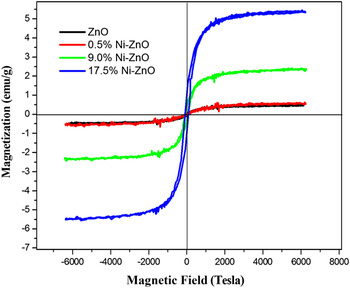
The magnetic properties of the samples were investigated by a VSM method at room temperature and are shown in Fig. 9. As shown in Fig. 9, the M–H curves of all samples showed hysteresis loops, which indicated that the samples have room-temperature ferromagnetism. It is noteworthy that the ZnO reference exhibited weak ferromagnetism, which may be ascribed to the presence of the Zn vacancies. Reference Khalid, Ziese, Setzer, Esquinazi, Lorenz, Hochmuth, Grundmann, Spemann, Butz, Brauer, Anwand, Fischer, Adeagbo, Hergert and Ernst65,Reference Wang, Sun, Chen, Kawazoe and Jena66 Additionally, the mass saturation magnetization (Ms) of the samples increased with increase of Ni loadings. The Ms samples are 0.48, 0.55, 2.35, and 5.40 emu g−1 for ZnO reference and Ni-decorated ZnO (with 0.5, 9.0, and 17.5 at.% Ni loadings), respectively. The strong mass saturation magnetization for Ni-decorated ZnO could be ascribed to the contribution of metal Ni. The results indicated that the as-prepared Ni-decorated ZnO composites have good ferromagnetism at room temperature. Thus, the Ni-decorated ZnO composites could be easily separated by external magnetic field.
Magnetic hysteresis curves of samples at room temperature.

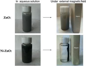
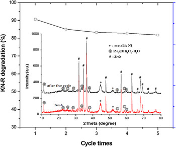
The magnetic recoverability of the as-synthesized samples was performed as illustrated in Fig. 10. It can be seen from Fig. 10 that the ZnO reference dispersed well in aqueous solution but cannot be separated by external magnetic field. Unlike ZnO reference, the Ni-decorated ZnO composite dispersed in an aqueous solution was easily collected by external magnetic field. This result indicated that Ni-decorated ZnO composites are magnetically recoverable. Furthermore, the recycled photodegradation experiments of KN-R were performed using Ni-decorated ZnO with 17.5 at.% Ni loadings owing to its high activity and strong ferromagnetism. The sample was re-collected by external magnetic field after each run lasted 120 min. As shown in Fig. 11, the photocatalytic activity of Ni-decorated ZnO showed remarkable decrease after the first run, while their photocatalytic activity did not conspicuously change in the following cycles. The remarkable decrease of photocatalytic activity after the first run may be attributed to the loss of powder with weak magnetic force. However, the Ni-decorated ZnO composite still exhibited great photocatalytic activities and little mass losses (recovery efficiency of 88%) after five cycles. Furthermore, it can be seen from Fig. 11 that the phase structure of the Ni-decorated ZnO composite is not changed after five cycles, which have demonstrated that the Ni-decorated ZnO composites are stable under photocatalysis process. The above results indicated that Ni-decorated ZnO composite is acceptable for use as a magnetically recoverable photocatalyst.
Magnetic-assisted recoverability of ZnO with and without Ni decorating.

The recycled photodegradation experiments of Ni-decorated ZnO (17.5% Ni) re-collected by external magnetic field. Insets: XRD patterns of samples before and after recycled photodegradation experiments.

IV. CONCLUSIONS
In summary, Ni-decorated ZnO composites with magnetic separable characteristics are prepared for the first time via a simple replacing-hydrothermal method. Interestedly, the introduced Ni element as Ni2+ ion incorporated into matrix of ZnO, and as metal Ni anchored on the surface of ZnO crystals. The introduction of Ni changed remarkable growth rate of different crystal faces of ZnO (resulted in the formation of ZnO with different morphologies such as nanorods, prism, and sheet-like ZnO crystals), and shifted the optical absorption edge to the visible region, and reduced the recombination of photogenerated electrons and holes. The photocatalytic degradation of KN-R revealed that the Ni-decorated ZnO composites have better photocatalytic activities than that of ZnO. The enhancement of photocatalytic activities of composites can be attributed to the existence of Ni2+ doping, Ni/ZnO heterostructure, and abundant adsorbed oxygen (as the electronic scavenges), which causing efficient separation of electron–hole pairs in Ni-decorated ZnO. Moreover, Ni introduction also endued ZnO photocatalyst with excellent magnetic recoverability. This research provides a new approach and opportunity for fabricating ZnO photocatalyst with improved photocatalytic activity and excellent magnetic recoverability.
Supplementary Material
To view supplementary material for this article, please visit http://dx.doi.org/jmr.2015.115.
ACKNOWLEDGMENTS
This work was supported by The National Natural Science Foundation of China (21243005, 21476033), Science & Technology Foundation of Liaoning of China (201102011), Program for Key Science & Technology Platform in Universities of Liaoning Province, Program for Liaoning Excellent Talents in University (LR2014013), and Science & Technology Public-Benefit Foundation of Liaoning of China ([2011]49).