1. INTRODUCTION
A star sensor, which measures the attitude of the host vehicle by imaging stars, is one of the main instruments of a Celestial Navigation System (CNS). A CNS can be totally autonomous and the attitude estimation using a star sensor can achieve an accuracy of one arc-second. The attitude error, which is not accumulated over the operation time, is stable over the long-term. Hence, the research and the applications of star sensors have been studied intensively for both spacecraft and aircraft for a long time (Liebe, Reference Liebe2002; Ju and Junkins, Reference Ju and Junkins2003; Ho, Reference Ho2012).
However, when the vehicle rotates quickly, the star image can be heavily smeared by the large angular displacement because of the strap-down star sensor, which leads to a severe reduction of the Signal-to-Noise Ratio (SNR) value of the smeared image. As a result, the accuracy of extracting a star centroid is seriously degraded. That is, fast manoeuvring may lead to failure of star Centroid Extraction (CE), which causes failure of Attitude Determination (AD) using the star sensor.
To reduce the effect of the image smearing, three compensation methods, including the mechanical method, the electronic method, and the digital-image-processing method, have been proposed (Denver, Reference Denver2004). The image smearing can be alleviated by compensating for the image displacement in exposure caused by the rotation of the star sensor mechanically or electronically. In the mechanical method, the mechanical system and its servo control system are very complicated. In the electronic method, the image smearing can be compensated only for one specific direction. Therefore, these two methods have limited application. The digital-image-processing method, however, has the advantages that it needs neither mechanical parts nor the control of the exposure circuit of the star sensor.
The CE error due to the star sensor rotation can be reduced upon analysis of the distribution of the star image grey values (Zhao et al., Reference Zhao, Wang, Wang and Ji2011). The smeared trace is assumed as a line in the compensation. However, because the smeared image is not restored, its SNR value cannot be improved. As a result the compensated CE accuracy is decreased with increase of the sensor's angular rate (Rufino and Accardo, Reference Rufino and Accardo2003). Meanwhile, the AD success rate is also reduced significantly with the decrease of the image SNR value. To resolve this problem, a Wiener Filter (WF) has been proposed to restore the smeared image (Quan and Zhang, Reference Quan and Zhang2011). However, the restoration is effective only when the Point Spread Functions (PSF) of the star sensor's rotation are unanimous. The star sensor's rotation can be decomposed into two components, across and around the bore-sight vector, respectively. The PSF of the star sensor's rotation can be modelled by convoluting the PSFs of these two rotation components in order to restore the smeared image (Wu and Wang, Reference Wu and Wang2011). However, it has been proven that the 2D image smearing can only be restored accurately by the 2D PSF directly (Wang and Zhao, Reference Wang and Zhao2002). In case of the large angular rate, e.g. 60°/s, a method was proposed to estimate the angular rate by use of the smeared trace instead of compensation for it (Liebe et al., Reference Liebe, Gromov and Meller2004). However, it has very poor estimation accuracy that limits its use.
In this paper, a new method is proposed to improve accuracy from two aspects – to compensate for the smeared trace as well as to restore the smeared image. Under the aid of the triaxial angular rate sensed by the Strap-down Inertial Navigation System (SINS), the trace due to the rotation around an arbitrary direction is firstly derived. Then, a WF is employed to restore the smeared image. In the proposed method, the WF is innovatively implemented by using a new Power Spectral Density (PSD) together with the PSF of the smeared image. A new tracking method is then proposed to use the SINS coarse attitude for rejecting the heavily-smeared images.
The paper is organised as follows. The smeared trace is derived and its length is calculated by use of the SINS angular rate in Section 2. The new restoration algorithm based on the WF is presented with the aid of the SINS coarse attitude in Section 3. A robust tracking method is proposed to improve the attitude estimation accuracy in Section 4. In the tracking method, the SINS coarse attitude is utilised to improve the AD success rate and shorten the star recognition time. The estimated starlight angle error further helps to reject the stars with large CE errors. The algorithm is demonstrated by simulations in Section 5.
2. THE SMEARED TRACE
It is assumed that the vehicle's manoeuvring causes the image smearing. High-frequency angular vehicle vibration is treated as noise. This assumption is reasonable since defocusing is generally applied to improve the CE accuracy. The small star image displacement caused by the vehicle's angular vibration can be assumed as part of the defocusing. The vehicle's low-frequency angular vibration can be treated as part of the vehicle's manoeuvring. It is also assumed that the vehicle's manoeuvring in exposure can be treated as the fixed-axis rotation with a constant angular rate if the exposure is short enough. These assumptions are applied to succeeding sections of the paper.
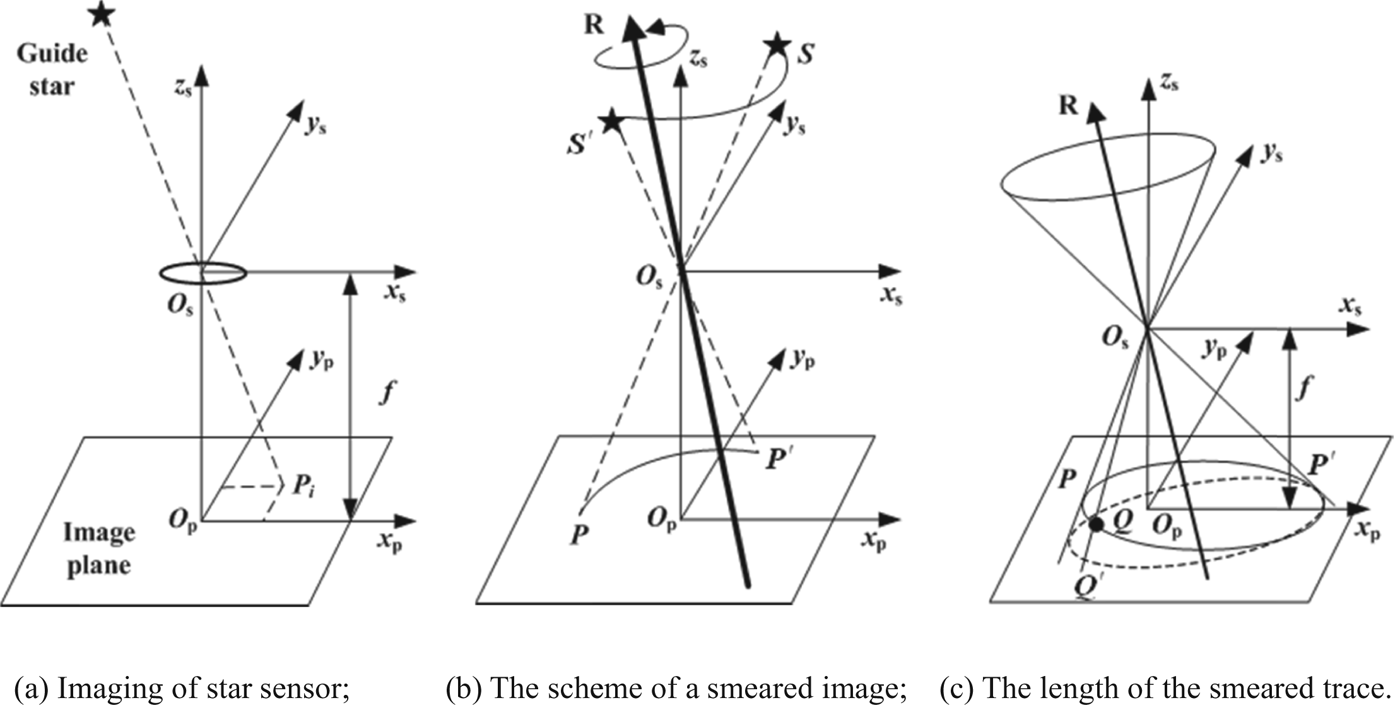
The image smearing can be equivalent to a star's rotation around the same axis in the opposite direction. When the star rotates, the starlight direction will move on a conical surface as shown in Figure A1(b) in the Appendix. The smeared trace is part of the intersection of the conical surface with the image plane, which is also derived in the Appendix.
3. THE RESTORATION OF THE SMEARED IMAGE
3.1. The restoration without the aid of the SINS coarse attitude
WF is a popular method used to restore the degraded image in the sense of the minimum variance between the filtered and the original images (Gonzalez and Woods, Reference Gonzalez and Woods2002). The traditional WF requires that the PSF of the smeared image is invariant to displacement, i.e., the PSFs at all points on the image have the same value. However, the PSF of the smeared image is variant to displacement in most scenarios. To resolve the problem, a one-dimensional (1D) WF with a specific PSF is designed for a smeared image.
Assume g(n) is the 1D array, which is the sample of a star image along its smeared trace, and h(n) is the 1D PSF determined by the smeared trace length. The PSF for the trace PP ′ shown in Figure A1 is
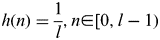 $$h(n) = {\displaystyle{1 \over l}},n{\rm \in} [0,l - 1)$$
where l is the smeared trace length as denoted in Equation (A7) in the Appendix.
Assume Fourier Transform (FT) of g(n) and h(n) as G(u) and H(u) respectively. WF for the trace is written as
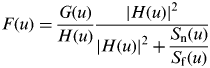 $$F(u) = \displaystyle{{G(u)} \over {H(u)}}\displaystyle{{{\rm |}H(u){\rm |}^2} \over {{\rm |}H(u){\rm |}^2 + \displaystyle{{S_{\rm n} (u)} \over {S_{\rm f} (u)}}}}$$
where S n(u) and S f(u) are the PSDs of noise and the original image, respectively. Theoretically, Equation (2) can be used to restore the smeared image by the rotation around any direction of star sensor, but implementation of Equation (2) is very complicated and would lead to a heavy computational load. Therefore, a new restoration algorithm with aid of the SINS coarse attitude is proposed below.
3.2. The restoration with aid of SINS
3.2.1. Estimation of the star position
In the integration of SINS/CNS, SINS can output the coarse attitude for CNS. The direction of the optical axis can be estimated by the SINS coarse attitude so that the possible stars in the Field Of View (FOV) of the star sensor can be found in the star catalogue. The stars' positions on the image plane can be acquired by coordinate transformation. Samaan et al. (Reference Samaan, Mortari, Pollock and Junkins2002) and Liu et al. (Reference Liu, Wang and Zhang2011) employed a similar method to improve CE speed. This method is used in the following to estimate the possible star position on the image plane.
Assume the right ascension and declination of a star A (α, β). The unit vector of the star in the celestial inertial frame is:
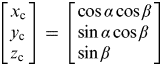 $$\left[ \matrix{x_{\rm c} \cr y_{\rm c} \cr z_{\rm c} } \right] = \left[ \matrix{\cos \alpha \cos \beta \cr \sin \alpha \cos \beta \cr \sin \beta } \right]$$
The transformation matrix Cis from the celestial frame to the star sensor frame can be approximated as Cis′ according to the SINS coarse attitude. The position of the star in the estimated star sensor frame is then written as:
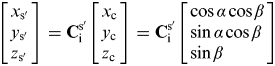 $$\left[ \matrix{x_{{\rm s}{\rm \prime}} \cr y_{{\rm s}{\rm \prime}} \cr z_{{\rm s}{\rm \prime}} } \right] = {\bf C}_{\rm i}^{{\rm s \prime}} \left[ \matrix{x_{\rm c} \cr y_{\rm c} \cr z_{\rm c} } \right] = {\bf C}_{\rm i}^{{\rm s \prime}} \left[ \matrix{\cos \alpha \cos \beta \cr \sin \alpha \cos \beta \cr \sin \beta } \right]$$
According to the geometry of the similar triangles, the position of the star on the image plane frame is:
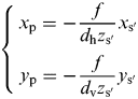 $$\left\{ {\matrix{ {x_{\rm p} = - \displaystyle{\,f \over {d_{\rm h} z_{{\rm s}{\rm \prime}}}} x_{\rm s {\rm \prime}}} \cr {y_{\rm p} = - \displaystyle{\,f \over {d_{\rm v} z_{{\rm s}{\rm \prime}}}} y_{\rm s\rm \prime}}} \cr}} \right.$$
where d h and d v are the height and the width of a pixel, respectively.
3.2.2. The error of the star position estimation
The SINS coarse attitude has an error in the estimated position of the star on the image plane. Assume Cis=TCis′ and the angular error between the real star sensor frame and its estimated 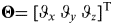 ${\bf \Theta} {\rm = [}\vartheta _x \;\vartheta _y \;\vartheta _z ]^{\rm T} $. If the angular error is small enough, the transformation matrix can be approximated as:
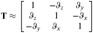 $${\bf T} \approx \left[ {\matrix{ 1 & { - \vartheta _z} & {\vartheta _y} \cr {\vartheta _z} & 1 & { {-} \vartheta _x} \cr { - \vartheta _y} & {\vartheta _x} & 1 \cr}} \right]$$
The real position of the star is:
 $$\left[ \matrix{x_{\rm s} \cr y_{\rm s} \cr z_{\rm s} } \right] = {\bf TC}_{\rm i}^{{\rm s \prime}} \left[ \matrix{x_{\rm c} \cr y_{\rm c} \cr z_{\rm c} } \right] \approx \left[ {\matrix{ 1 & { - \vartheta _z} & {\vartheta _y} \cr {\vartheta _z} & 1 & { - \vartheta _x} \cr { - \vartheta _y} & {\vartheta _x} & 1 \cr}} \right]\left[ \matrix{x_{{\rm s}{\rm \prime}} \cr y_{{\rm s}{\rm \prime}} \cr z_{{\rm s}{\rm \prime}} } \right]$$
The position error is:
 $$\left[ \matrix{\Delta x_{\rm s} \cr \Delta y_{\rm s} \cr \Delta z_{\rm s} } \right] = \left[ \matrix{x_{\rm s} \cr y_{\rm s} \cr z_{\rm s} } \right] - \left[ \matrix{x_{{\rm s}{\rm \prime}} \cr y_{{\rm s}{\rm \prime}} \cr z_{{\rm s}{\rm \prime}} } \right] = \left[ {\matrix{ 0 & { - \vartheta _z} & {\vartheta _y} \cr {\vartheta _z} & 0 & { - \vartheta _x} \cr { - \vartheta _y} & {\vartheta _x} & 0 \cr}} \right]\left[ \matrix{x_{{\rm s \prime}} \cr y_{{\rm s}{\rm \prime}} \cr z_{{\rm s}{\rm \prime}} } \right] = \left[ {\matrix{ {\vartheta _y z_{{\rm s}{\rm \prime}} - \vartheta _z y_{{\rm s}{\rm \prime}}} \cr {\vartheta _z x_{{\rm s}{\rm \prime}} - \vartheta _x z_{{\rm s}{\rm \prime}}} \cr {\vartheta _x y_{{\rm s}{\rm \prime}} - \vartheta _y x_{{\rm s}{\rm \prime}}} \cr}} \right]$$
According to Equation (5), there is:
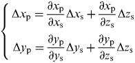 $$\left\{ {\matrix{{\Delta x_{\rm p} = \displaystyle{{\partial x_{\rm p}} \over {\partial x_{\rm s}}} \Delta x_{\rm s} + \displaystyle{{\partial x_{\rm p}} \over {\partial z_{\rm s}}} \Delta z_{\rm s}} \cr {\Delta y_{\rm p} = \displaystyle{{\partial y_{\rm p}} \over {\partial y_{\rm s}}} \Delta y_{\rm s} + \displaystyle{{\partial y_{\rm p}} \over {\partial z_{\rm s}}} \Delta z_{\rm s}} \cr}} \right.$$
where
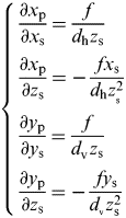 $$\left\{ \matrix{\displaystyle{{\partial x_{\rm p}} \over {\partial x_{\rm s}}} = \displaystyle{\,f \over {d_{\rm h} z_{\rm s}}} \cr \displaystyle{{\partial x_{\rm p}} \over {\partial z_{\rm s}}} = - \displaystyle{{\,fx_{\rm s}} \over {d_{\rm h} z_{_{\rm s}} ^2}} \cr \displaystyle{{\partial y_{\rm p}} \over {\partial y_{\rm s}}} = \displaystyle{\,f \over {d_{_{\rm V}} z_{\rm s}}} \cr \displaystyle{{\partial y_{\rm p}} \over {\partial z_{\rm s}}} = - \displaystyle{{\,fy_{\rm s}} \over {d_{_{\rm v}} z_{{\rm s}} ^2}} } \right.$$
Substituting Equations (8) and (10) into Equation (9), yields:
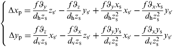 $$\left\{ {\matrix{ {\Delta x_{\rm p} = \displaystyle{{\,f\vartheta _y} \over {d_{\rm h} z_{\rm s}}} z_{{\rm s}{\rm \prime}} - \displaystyle{{\,f\vartheta _z} \over {d_{\rm h} z_{\rm s}}} y_{{\rm s}{\rm \prime}} + \displaystyle{{\,f\vartheta _y x_{\rm s}} \over {d_{\rm h} z_{\rm s}^2}} x_{{\rm s}{\rm \prime}} - \displaystyle{{\,f\vartheta _x x_{\rm s}} \over {d_{\rm h} z_{\rm s}^2}} y_{{\rm s}{\rm \prime}}} \cr {\Delta y_{\rm p} = \displaystyle{{\,f\vartheta _z} \over {d_{\rm v} z_{\rm s}}} x_{{\rm s}{\rm \prime}} - \displaystyle{{\,f\vartheta _x} \over {d_{\rm v} z_{\rm s}}} z_{{\rm s}{\rm \prime}} + \displaystyle{{\,f\vartheta _y y_{\rm s}} \over {d_{\rm v} z_{\rm s}^2}} x_{{\rm s}{\rm \prime}} - \displaystyle{{\,f\vartheta _x y_{\rm s}} \over {d_{\rm v} z_{\rm s}^2}} y_{{\rm s}{\rm \prime}}} \cr}} \right.$$
It should be noticed that z s is far larger than x s and y s so that the maxima of x s/z s and y s/z s are less than tan 7·5° in the FOV of 15°×15°. Thus, Equation (11) can be approximated as:
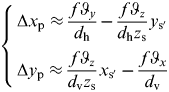 $$\left\{ {\matrix{ {\Delta x_{\rm p} \approx \displaystyle{{\,f\vartheta _y} \over {d_{\rm h}}} - \displaystyle{{\,f\vartheta _z} \over {d_{\rm h} z_{\rm s}}} y_{{\rm s}{\rm \prime}}} \cr {\Delta y_{\rm p} \approx \displaystyle{{\,f\vartheta _z} \over {d_{\rm v} z_{\rm s}}} x_{{\rm s}{\rm \prime}} - \displaystyle{{\,f\vartheta _x} \over {d_{\rm v}}}} \cr}} \right.$$
If the star sensor's resolution is 512×512 and its FOV is 15°×15°, Δx p and Δy p will not exceed 40 pixels even though  $\vartheta _x, \;\vartheta _y $, and
 $\vartheta _z $ are as large as 1°.
3.2.3. Restoration for the local smeared image
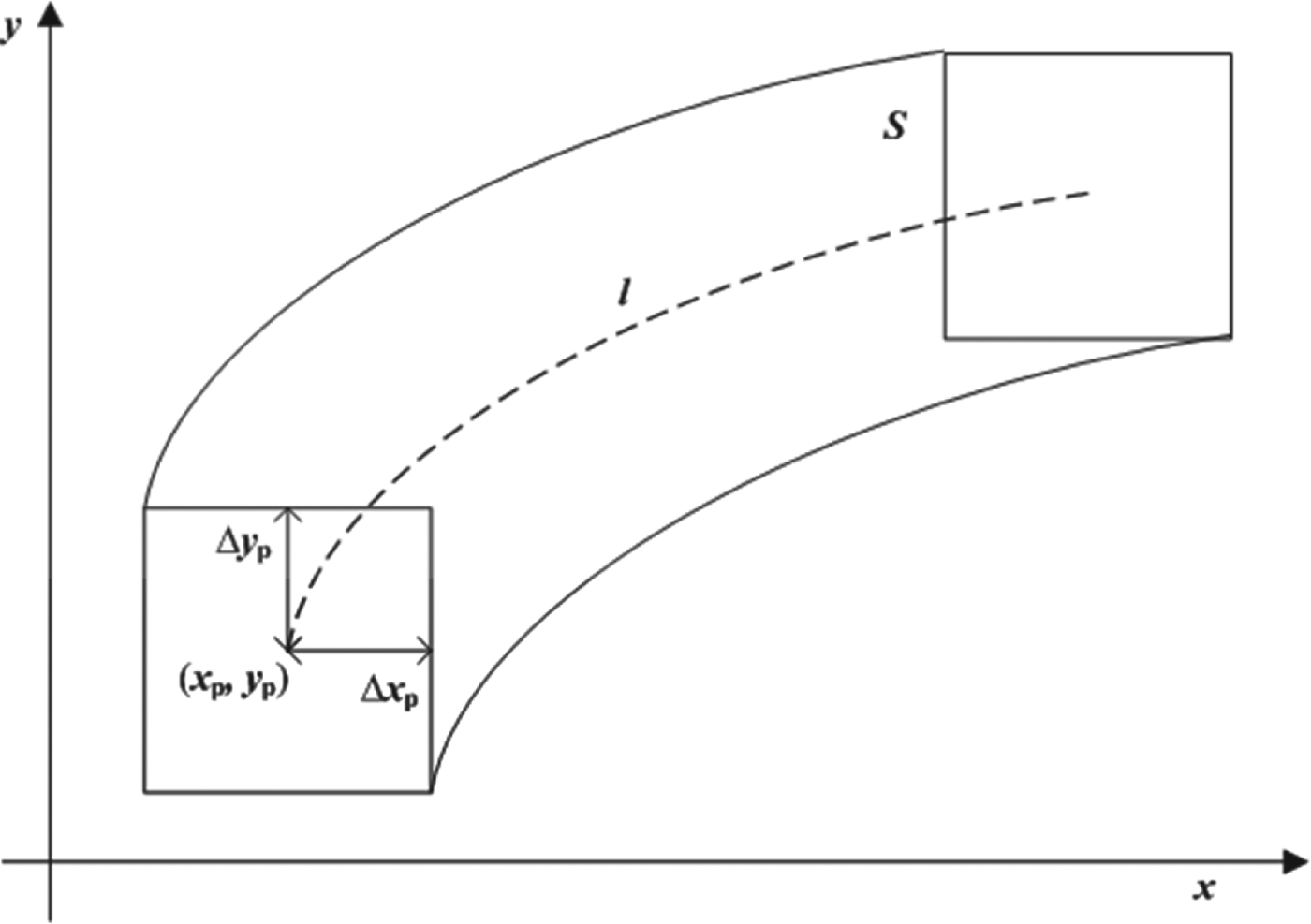
In Figure 1, the smeared trace and its length l of a star image with its original position (x p, y p) can be derived with the aid of SINS. The local smeared image of the star is within a rectangular zone with the centre of (x p, y p) in the range of (±Δx p,±Δy p). Since Δx p and Δy p are small, the smeared traces and their lengths of all the points are assumed to be the same in the rectangular zone so that the PSF at any point in the rectangular zone is the same as that at the point of (x p, y p), which can reduce the following restoration's computational load significantly. WF can be then designed as follows.
(1) Calculate the smeared trace and its length according to Equations (A6) and (A7) with the aid of the SINS angular output at the point of (x p, y p).
(2) Acquire the PSF h(x,y) of the local zone. The grey value of the local zone is g(x,y).
(3) The FTs of h(x,y) and g(x,y) are H(u,v) and G(u,v) respectively.
(4) WF is written as
The estimated zone of a smeared image.

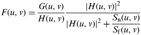 $$F(u,v) = \displaystyle{{G(u,v)} \over {H(u,v)}}\displaystyle{{{\rm |}H(u,v){\rm |}^2} \over {{\rm |}H(u,v){\rm |}^2 + \displaystyle{{S_{\rm n} {\rm (}u,v)} \over {S_{\rm f} {\rm (}u,v)}}}}$$
where S n(u,v) and S f(u,v) are the PSDs of noise and the original image in the local zone. S n(u,v)/S f(u,v) is usually assumed as a constant in restoration since S f(u,v) is unknown, which will degrade the restoration accuracy. To improve the restoration accuracy, S f(u,v) is estimated for the smeared image as follows. The energy of a static star image can be modelled as a 2D Gaussian distribution, i.e.
 $$f\,(x,y) = \displaystyle{ \rho \over {2{\rm \pi} \sigma ^2}} \exp \left[ { - \displaystyle{{(x - x_0 )^2 + (y - y_0 )^2} \over {2\sigma ^2}}} \right]$$
where ρ is determined by the star luminance and can be calculated by the star magnitude; σ is the defocusing scope of the star image which is determined by the star sensor; and (x 0, y 0) is the centre of the star image. The centre is independent to the amplitude of the star image's FT. Hence the PSF of the star image is invariant to the position of its centre. If the FT of f(x,y) is F f(u,v), the PSF of f(x,y) is the squared complex conjugate of F f(u,v), i.e.,
 $$S_{\rm f} (u,v) = {\rm |}F_f (u,v){\rm |}^2 $$
where both x 0 and y 0 can be assumed as 0 for convenience. S n (u,v) is a constant for white noise, which can be estimated by the image without stars.
4. THE TRACKING METHOD WITH THE AID OF SINS
With the aid of the SINS coarse attitude, it is ideal to have only one smeared image in the local zone as shown in Figure 1 so that the one-to-one correspondence of the star positions on the image plane and in the celestial frame can be used to estimate the attitude of the star sensor. However, the aided CE may be seriously degraded in some scenarios. For example, if the vehicle's angular rate is very large, part of other star images may be embraced in the local zone so that the restoration accuracy will be degraded. Meanwhile, the CE accuracy will be reduced accordingly. The extracted position may be wrong when the SNR is very low since the star image is swamped by noise. Moreover, the AD accuracy may be degraded seriously if the CE accuracy of one star is reduced. For example, if there are nine stars in the FOV and the CE errors of eight stars are δ and the CE error of one star is 30δ, the attitude error of the least-squares estimation is  ${\delta} ^{\rm \prime} = \sqrt {(30 \times 30 + 8)/(9 \times 9)} {\rm \delta} \approx 3{\cdot}35 \delta $, but it is about 0·35δ if it only uses the eight stars with small errors of δ. Hence it is necessary to identify and reject the stars with very large CE errors.
In this paper, the stars with the large CE errors are identified by the differenced angular distances. It is assumed that in the FOV, the angular distances from one star to others in the star catalogue are {d i}(i=1, 2, …, n), and the angular distances from the extracted star to others on the image plane are {d i′}(i=1, 2, …, n). The difference of the two sets of angular distances is calculated as 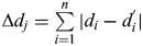 $\Delta d_j = \sum\limits_{i = 1}^n {{\rm |}d_i - d_i^{\rm \prime} {\rm |}} $. For all of the stars in the FOV, the differences are calculated, i.e., {Δd j}(j=1,2, …, n+1). If the CE error of one star is very large, the difference of the two sets of angular distances will be significantly larger than others so that the star can be rejected in AD.
5. SIMULATIONS
5.1. The main conditions
The star images are simulated using the Smithsonian Astrophysical Observatory (SAO) star catalogue J2000. Only the stars with a magnitude no greater than 7 Mv are simulated. The energy distribution of the simulated stars follows
 $$G(x,y) = AG_{{\rm norm}} (x,y)$$
where A is the amplitude and G norm(x,y) as described by Wang et al. (Reference Wang, Zhou and Cheng2012) is the normalised energy distribution. The value of A is determined by both the exposure and the magnitude threshold that the star sensor can image. Since the magnitude threshold of the star sensor is set as 7 Mv, the amplitude of a 7 Mv star image is five times the noise standard deviation when there is no vehicle manoeuvring. The amplitude of a star image with other magnitudes can be derived as
 $$A_2 = 2{\cdot}512^{M_1 - M_2} \times A_1 $$
where A 1 and A 2 are the amplitudes of the star images with the magnitudes of M 1 and M 2 and M 1=7Mv. The specifications of the star sensor are listed in Table 1.
The specifications of the star sensor.

5.2. The performance of the proposed method
If the SINS is accurate enough, the impact of vehicle manoeuvring on the star sensor can be effectively compensated. That is, with the aid of SINS, the smeared image can be restored to improve its SNR value so that the AD success rate and the AD accuracy can be improved. However, if the SINS error is very large, the proposed restoration and tracking method may fail to converge. The influence of the SINS error on the proposed method is evaluated in Section 5.3.
5.2.1. The SNR values of the smeared image
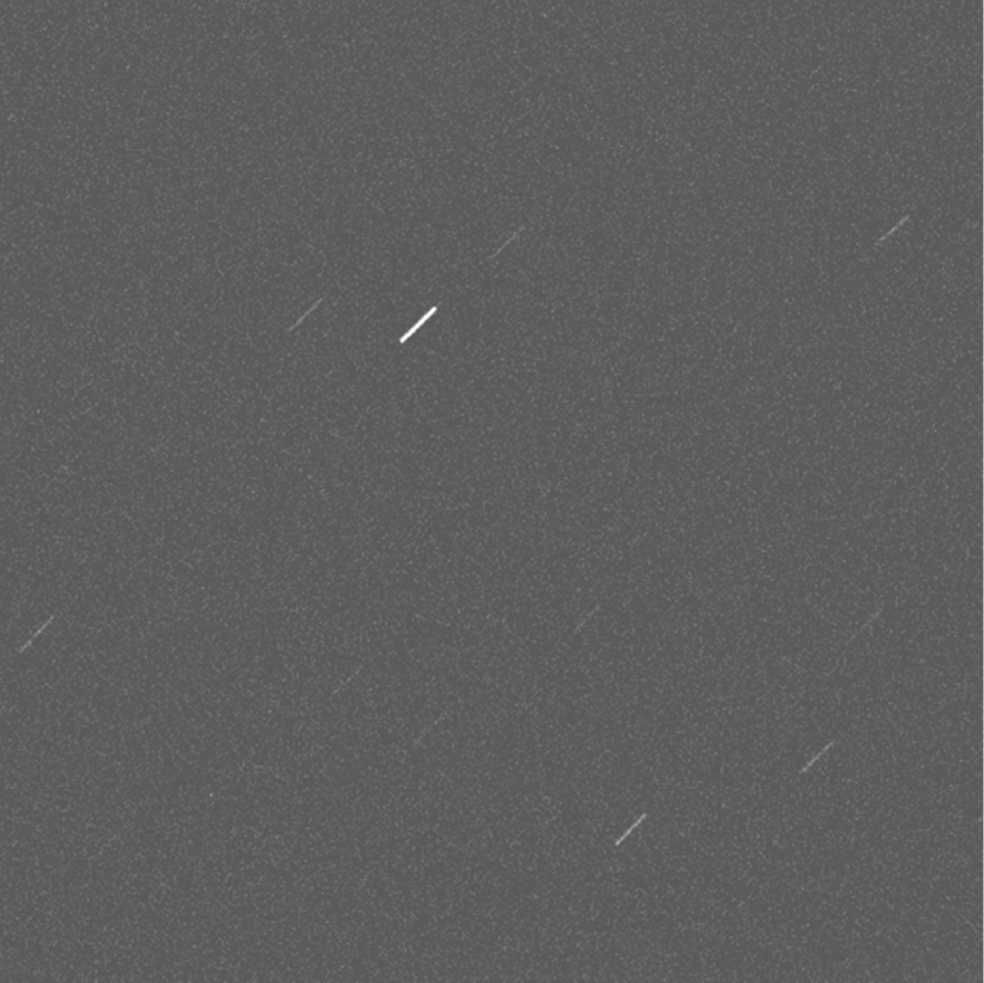
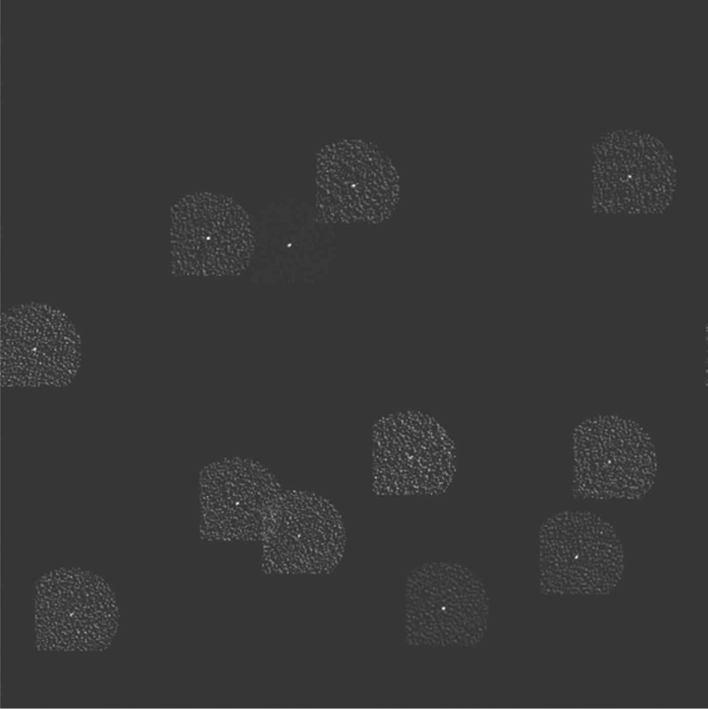
The smeared image is shown in Figure 2 when the star sensor's angular rates around x s, y s, and z s axes are −5·1°/s, 5°/s, and 3°/s respectively. The initial direction of the optical axis in the celestial frame is (96·1°, 34·95°). The restored images for all the stars in Figure 2 are depicted in Figure 3, from which it can be found that the dispersed energy of the smeared image has been accumulated by restoration. In Figure 3, the contrast of the star images is increased to make them clear in view. All of the restored images are contaminated by noise, but the noise strengths vary with different images. Some restored images in Figure 3 partially overlap, which will degrade the CE accuracy and thus be rejected. The grey values of a smeared image are shown in Figure 4 (without restoration) and Figure 5 (with restoration). The star energy is spread along a trace and the greatest grey value is about 12 in Figure 4 whereas it is accumulated in a small zone and the greatest grey value is over 150 in Figure 5.
The smeared image.
The image restored with the proposed WF.
The grey values of a smeared image without restoration.
The grey values of a smeared image with restoration.
If SNR is defined as the ratio of the peak value of the restored image to the standard deviation of noise, the restoration can be evaluated by SNR analytically. The vehicle manoeuvring leads to the image smearing so that its SNR value is reduced accordingly due to the spread energy. In contrast, the SNR value of the restored image will be increased significantly due to the accumulated energy. Figure 6 depicts the SNR values with and without restoration. The vehicle's angular rate in Figure 6 is perpendicular to the optical axis. In Figure 6, if the angular rate is lower than 1°/s, the difference between the SNR values with and without restoration is small. When the angular rate is larger than 1°/s, the SNR improvement is obvious for the restoration. Hence, the restoration is more effective in cases of large angular rate than for smaller angular rates.
The SNR value of a star image with and without restoration.
5.2.2. The success rate and the accuracy of AD
The impact of the image smearing on AD lies in two aspects: (1) the reduced SNR value reduces the number of the identified stars in the FOV, and (2) the CE accuracy of the identified stars is degraded. Hence the attitude accuracy of the star sensor will be reduced when the vehicle is manoeuvring. If the vehicle is manoeuvring so fast that fewer than two stars are identified, AD will fail with use of the star sensor. To evaluate the effect of the vehicle's manoeuvring on AD, the AD success rate and the AD accuracy with the different vehicle's angular rates are studied by Monte Carlo simulations. The star image is simulated 500 times at each vehicle angular rate. The vehicle angular rate is also perpendicular to the optical axis, which is the worst scenario for the proposed method. The averaged AD success rate and the averaged AD accuracy are depicted in Figures 7 and 8 respectively. In the simulations, the SINS coarse attitude error is modelled as a Gaussian noise with zero mean and the standard deviation of 0·3°. The results of different methods are compared in Figures 7 and 8, which include (1) the ‘Restoration And Tracking (RAT)’ method that combines the proposed restoration algorithm and the tracking method, (2) the method without restoration, and (3) the ‘Restoration And Matching (RAM)’ method that combines the proposed restoration algorithm and the improved triangle matching algorithm (Liu et al., Reference Liu, Wang and Zhang2011).
The AD success rate.
The AD error.
In Figure 7, the AD success rate without restoration is decreased linearly with the increase of the vehicle angular rate. When the vehicle's angular rate is larger than 6°/s, AD fails since fewer than two stars are identified. The large vehicle angular rate leads to a seriously smeared image so that the SNR value of the star image is decreased and AD has a low accuracy or simply fails. The AD success rate with RAM is reduced with an increase of the vehicle's angular rate. If the vehicle's angular rate is as large as 15°/s, the AD success rate will be decreased to 30%. Hence, the AD success rate with RAM should be improved further. The AD success rate with RAT is higher than that with RAM by about 10% when the vehicle's angular rate is larger than 5°/s. The SNR value of the star image is improved by restoration and the stars with the large CE error are rejected by the tracking method so that the AD success rate is improved further with RAT.
In Figure 8, the attitude error with the vehicle's angular rate is plotted when AD is successful. The attitude error is the norm of the angle errors in the three directions of the star sensor frame. The results in Figures 7 and 8 are coincident with each other. With increase of the angular rate, the attitude error without restoration is increased sharply, but the attitude errors of the two algorithms with restoration are increased slowly. Furthermore, the attitude error of the tracking method is lower and more stable than that of the matching method. The advantages of the tracking method over the matching method include: (1) the accuracy of the tracking method is less sensitive to the CE accuracy than that of the matching method, and (2) the identified stars by the tracking method are more than those by the matching method. In the simulations, the average number of the identified stars by the tracking method is about 5·93 against 3·83 from the matching method. If the CE accuracy is of the same order, the AD error is inversely proportional to the square root of the number of the identified stars. Hence, the AD accuracy of the tracking algorithm is higher.
It should be noted that the attitude error with restoration is relatively large when the vehicle angular rate is small as shown in the zoomed-in Figure 8. This is because the smeared trace due to the small angular rate can be covered in the defocused zone of the star image so that the vehicle's manoeuvring has little impact on CE, but the CE accuracy will be degraded unavoidably by the proposed restoration algorithm since the WF bandwidth is finite. However, the difference between the attitude errors with and without restoration is very small under a low vehicle angular rate.
5.3. The effect of SINS on the proposed method
In the proposed method, the restoration algorithm proposed in Section 3 is aided by SINS. If SINS has a large error, the aided star sensor may have degraded performance. The effects of SINS on the proposed algorithm include:
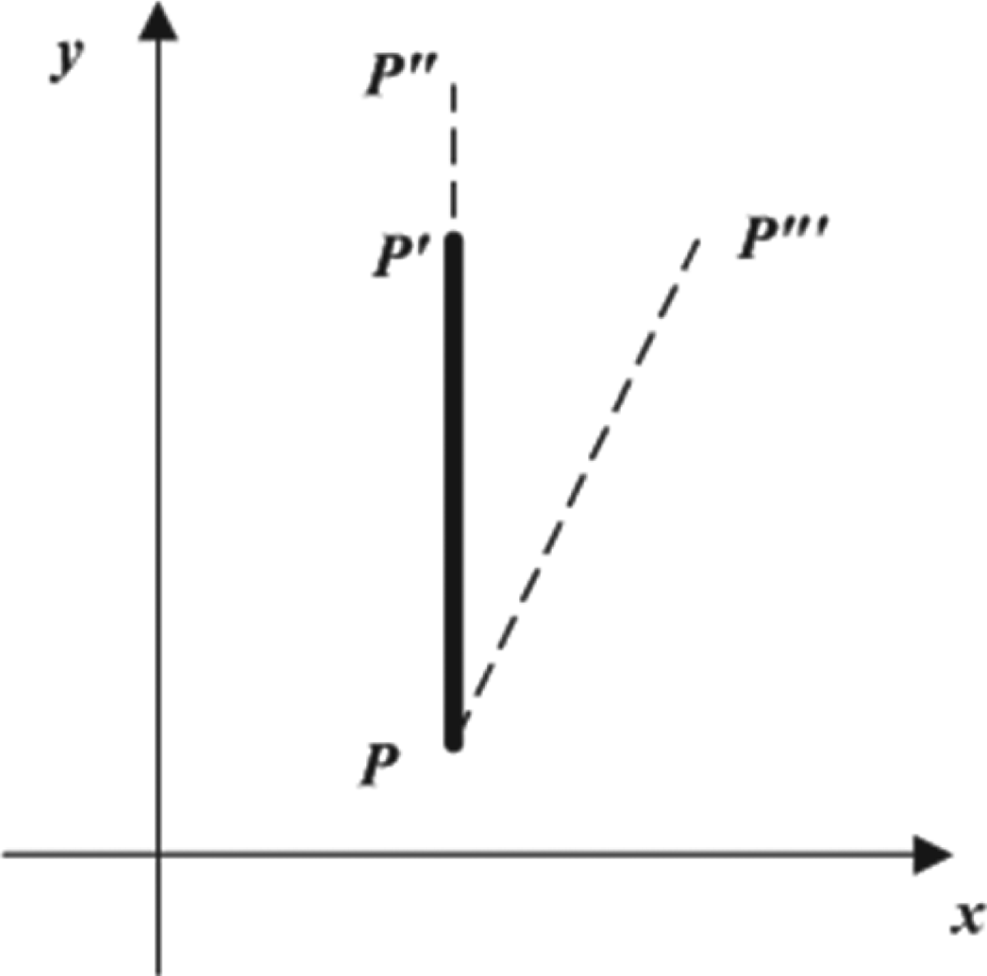
(1) Estimation of a smeared trace depends heavily on the SINS angular rate accuracy. The estimation error of the smeared trace will be increased with the angular rate errors in one or more axes in the SINS solution, which will degrade the AD accuracy. As depicted in Figure 9, the real smeared trace is PP′ if the vehicle's angular rate is around the x s axis, but its estimation is either PP″ which is shortened or extended by the SINS angular rate error in the x s axis, or PP‴ which is slanted by the SINS angular rate error in the y s axis. If the vehicle's angular rate is around the y s axis, the estimated smeared trace will be distorted by the SINS angular rate error in the x s and/or y s axis similarly. If there are vehicle angular rates in both x s and y s axes, the estimated smeared trace will be deformed by the SINS angular rate errors in the x s and/or y s axis. Since the image plane is perpendicular to z s axis, the SINS angular rate error in the z s axis does not affect the estimated smeared trace as significantly as those in the other two axes, which will be verified by simulations.
(2) The impact of the SINS coarse attitude error on the restoration lies in three aspects: (a) if the SINS coarse attitude error is underestimated, the estimated rectangular zone in Figure 1 is so small that the smeared image is not covered fully in the rectangular zone, which accordingly leads to the failed CE; (b) if the rotating axis approaches to the optical axis, the estimated rectangular zone of one star image may be wrongly treated as the zone of another, which results in a wrong CE; and (c) if the vehicle's angular rate is very large, the estimated rectangular zone may cover more than one star's image so that the CE accuracy is degraded. Hence, the SINS coarse attitude error influences AD directly. Ideally, Equation (12) should be used to estimate the SINS coarse attitude error, but it will increase the computational load significantly. If a bounded coarse attitude error is employed properly, AD will not be affected in most scenarios as long as the vehicle's angular rate is not incredibly large, e.g. 30°/s. In the implementation, Δx p and Δy p are set as 40 pixels to cover the smeared image in the zone as much as possible.
The scheme of the estimated smeared trace with the aid of SINS.
5.3.1. The effect of SINS angular rate accuracy
The attitude error with a SINS angular rate error is depicted in Figure 10, where the horizontal axis is the error deviated from the real vehicle's angular rate. In the simulations, the vehicle's angular rate is set as 5°/s rotating around the x s axis. The initial direction of the optical axis in the celestial frame is (120·15°, −30·12°).
The attitude error with the SINS angular rate error.
In Figure 10(a), the attitude error in the x s axis is increased with the SINS angular rate error in the x s axis whereas those in the other two axes are stable. In Figure 10(b), only the attitude error in the y s axis is increased with the SINS angular rate error in the y s axis, which is similar to Figure 10(a). The reasons include (1) the estimated smeared trace is distorted by the SINS angular rate error, (2) the attitude error in the z s axis is one magnitude order larger than those in other two axes, and (3) the smeared trace can be decomposed into two components due to the rotations around and across the z s axis respectively. Hence, the attitude error in the z s axis varies significantly as long as there is the component due to the rotation around the z s axis but it is insensitive to the SINS' angular rate error in the x s or y s axis.
In Figure 10(c), the attitude errors in the three axes are insensitive to the SINS angular rate error in the z s axis. The attitude errors in the x s and y s axes are less affected by the SINS angular rate error in the z s axis since the attitude error in the z s axis is one magnitude order larger than those in the x s and y s axes. The attitude error in the z s axis is stable since the SINS angular rate error in the z s axis is not large enough. It is proven by simulations that the attitude error in the z s axis will keep increasing linearly with increase of the SINS angular rate error in the z s axis in the case of the SINS angular rate error in the z s axis larger than 0·5 °/s.
It is also noted that the attitude errors are less than 0·04° in the x s and y s axes and less than 0·1° in the z s axis even though the SINS angular rate error is as large as 0·2°/s. With a tactical-level gyroscope with the scale factor's non-linearity better than 0·1% and the bias less than 1°/h, the SINS has an error of less than 0·1°/s even though the vehicle's angular rate is as large as 50°/s. Hence, a tactical-level SINS meets the requirement of the proposed algorithm.
5.3.2. The effect of the SINS coarse attitude error
Since the SINS coarse attitude error around the optical axis has less impact on AD, only the error perpendicular to the optical axis is taken into account. Figure 11 depicts the norm of the attitude errors with the SINS coarse attitude errors in the x s axis when the vehicle rotates around the x s axis with an angular rate of 2·5°/s, 5°/s, or 7·5°/s. The initial direction of the optical axis in the celestial frame is (114·59°, −28·65°). In Figure 11, the SINS coarse attitude error has little impact on the attitude accuracy at these angular rates. Since the estimated rectangular zone is set as (±40 pixels, ±40 pixels), if the vehicle's angular rate is not very large, the smeared image can be restored accurately to achieve a stable AD accuracy. The small fluctuation of the attitude error may be due to random characteristics in the simulated images. With increase of the vehicle angular rate, the attitude error tends to increase in Figure 11. The main reason is that the SNR value of the smeared image will be reduced if the vehicle angular rate increases so that the restoration accuracy is degraded accordingly.
The attitude error with the SINS coarse attitude error.
5.3.3. The comprehensive effect of the SINS errors
Since there are both angular rate errors and attitude errors in the SINS solution, it is necessary to validate their total effect on the proposed algorithm.
If the misalignment error is neglected and the inertial frame is selected as the navigation frame, the SINS attitude error follows:
 $${\rm \dot \Psi} = - {\bf C}_{\rm b}^{\rm n} \delta {\rm K}{\bf \omega} _{{\rm ib}}^{\rm b} - \rm \varepsilon ^{\rm n} $$
where Ψ is the attitude error vector;  ${\bf \omega} _{{\rm ib}}^{\rm b} $ is the measured body angular rate vector in the body frame; Cbn is the rotation matrix from the body frame to the navigation frame; δ K is the scalar error coefficient; and εn is the gyroscope bias.
Figure 12 shows the norm of the attitude errors of SINS and SINS/CNS when the vehicle rotates at rates of 2·5°/s, 5°/s, and 7·5°/s around the x s axis for 250 s with the period of iteration of 5 s. The initial direction of the optical axis in the celestial frame is (18·21°, 57·31°). Since the SINS attitude is independent to the output of accelerometer in the inertial frame, only the performance of gyroscope is listed in Table 2.
The attitude errors of SINS and SINS/CNS.
The specifications of the gyroscope.

Figure 12 shows that the attitude error of the integration of SINS/CNS converges with time, but the attitude error of SINS diverges with time. The attitude error of SINS/CNS in Figure 12 is slightly larger than that in Figure 11 at a same angular rate. The reason is that the SINS has both an angular rate error and an attitude error in Figure 12, whereas only the SINS coarse attitude error in Figure 11. The SINS attitude error in Figure 12 tends to be bigger with increase of the angular rate, which is due to the scale factor error of the gyroscope listed in Table 2. Hence, the proposed algorithm is effective as long as the vehicle's angular rate is not too large.
6. CONCLUSIONS
When the host vehicle is manoeuvring, the star image will be smeared due to the rotation of the star sensor. In this paper, the smeared trace is derived when the star sensor rotates around an arbitrary axis. With the aid of the SINS angular rate and its coarse attitude, a new restoration algorithm based on a WF for any smeared trace is proposed. A tracking method is further proposed to reject the stars with a large centroid extraction error. Simulation results validate the effectiveness of the proposed method. Both the AD success rate and the AD accuracy are improved significantly even under very large vehicle angular rates.
APPENDIX: DERIVATION OF THE SMEARED TRACE
Figure A1(a) depicts the imaging of a star sensor schematically based on the pinhole model. In Figure A1(a), O px py p is the image plane frame whose origin Op is the intersection of the optical axis with the photo-sensing plane. O px p is perpendicular to O py p. O px p and O py p are parallel to the row and column directions of the photo-sensing plane. O sx sy sz s is the star sensor frame whose origin O s is the pinhole. O sx s and O sy s are parallel to O px p and O py p respectively. O sz s is along the optical axis. P i is the position of a star image on the image plane. f is the focus length.
Schemes of the smeared image due to the star sensor's rotation.
When the star sensor rotates around a fixed-axis in exposure, the star image will move on the photo-sensing plane that causes it to smear. The image smearing can be equivalent to the star rotating around the same axis O sR as shown in Figure A1(b) in the opposite direction. In the exposure, if the star S moves to S′, its image P will move to P′ on the image plane. When the star rotates, the starlight direction O sS will move on a conical surface.
The arc PP′ is the smeared trace, which is part of the intersection of the conical surface with the image plane. The intersection may be an ellipse, a parabola, or a hyperbola, which is derived as follows.
If O sR is along z s, the conical surface can be expressed as,
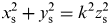 $$x_{\rm s}^2 + y_{\rm s}^2 = k^2 z_{\rm s}^2 $$
Where k=tan θ and θ is the angle between O sR and O sS. If O sR is not along z s, the expression of the conical surface in O sx sy sz s is more complicated than Equation (A1). In fact, the conical surface whose rotating axis is not along z s can be acquired by rotating the conical surface whose rotating axis is along z s twice. The first rotation is around y s by the angle φ (φ∈(−90°, 90°)) so that Equation (A1) can be rewritten as,
 $$(x_{\rm s} \cos \varphi - z_{\rm s} \sin \varphi )^2 + y_{\rm s}^2 = k^2 (x_{\rm s} \sin \varphi + z_{\rm s} \cos \varphi )^2 $$
Let
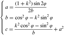 $$\left\{ \matrix{a = \displaystyle{{(1 + k^2 )\sin 2\varphi} \over {2b}} \cr b = \cos ^2 \varphi - k^2 \sin ^2 \varphi \cr c = \displaystyle{{k^2 \cos ^2 \varphi - \sin ^2 \varphi} \over b} + a^2 } \right.$$
Substituting Equation (A3) into Equation (A2) yields:
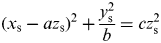 $$(x_{\rm s} - az_{\rm s} )^2 + \displaystyle{{y_{\rm s}^2} \over b} = cz_{\rm s}^2 $$
Then, the conical surface is rotated for the second time around z s by the angle γ (γ ∈ (0°,360°)) so that Equation (A4) can be rewritten as,
 $$(x_{\rm s} \cos \gamma - y_{\rm s} \sin \gamma - az_{\rm s} )^2 + \displaystyle{{(x_{\rm s} \sin \gamma + y_{\rm s} \cos \gamma )^2} \over b} = cz_{\rm s}^2 $$
Hence, the intersection of the conical surface with the image plane is
 $$(x_{\rm s} \cos \gamma - y_{\rm s} \sin \gamma + af)^2 + \displaystyle{{(x_{\rm s} \sin \gamma + y_{\rm s} \cos \gamma )^2} \over b} = cf^2 $$
The quadratic curve defined by Equation (A6) is the smeared trace due to the star sensor rotation around a fixed axis. The trace in exposure is part of the quadratic curve, which is the basis of the compensation for the smeared image. It is derived as follows.
Assume Q is a point on PP′ in Figure A1(c). Q′ is the intersection of O sQ with the circle in dash line. The circle is the intersection of the conical surface with the plane that is perpendicular to O sR and passes P. In exposure, the star sensor rotates in a constant angular rate around O sR so that Q′ also moves along the circle on the dashed line with the same angular rate. Assume d is the length of O sP. The smeared trace length on the circle in dash line l can be calculated as
 $$l = \phi d\sin \theta $$
where ϕ is the central angle of the circle in dash line while the star image moves from P to P′. Q moves along PP′ with the variable angular rate since the length of O sQ is variable. However, the length of O sQ approximates that of O sQ′, which can be proven by Equation (A8).
 $$\max ({\rm |}O_{\rm s} Q{\rm |/|}O_{\rm s} Q{\rm \prime} {\rm |}) = \cos {\textstyle{\lambda \over 2}}$$
where λ is the angle of the FOV and |O sQ| and |O sQ′| are the lengths of O sQ and O sQ′ respectively. If the FOV is 15°×15°, the difference between |O sQ| and |O sQ′| is no more than 1% of |O sQ|. Hence, it is reasonable to assume that Q moves along PP′ with a constant angular rate as Q′ moving along the circle in dash line so that the length of PP′ approximates l.