I. INTRODUCTION
Titania (TiO2) in its rutile form is an important material in industry, with industrial scale uses from pigmentation in paint to sunscreen. This work, however, is focused on its use within photovoltaic devices. High quality, dense films of TiO2 are used extensively in multilayer optical coatings because of their high refractive index and ability to absorb ultraviolet radiation.Reference Zhang, Anderson and Moo-Young1 Porous TiO2 is used in dye-sensitized solar cells.Reference Wang, Su, Chen, Liu, Hsu, Hsu and Li2 The porous TiO2 is immersed in a ruthenium-polypyridine dye,Reference Schwarz, Loyen, Jockusch, Turro and Durr3 where a thin film of the dye bonds to the TiO2, which acts as an anode.
Metal oxide thin films can be deposited using a variety of industrial scale processes, including evaporation (thermal and electron beam), ion-beam-assisted evaporation,Reference Wolfe and Singh4–Reference Zhang, Jin, Mao, Zheng, Chen and Liu6 and reactive magnetron sputtering.Reference Bange, Ottermann, Anderson, Jeschkowski, Laube and Feile5, Reference Kim, Lee, Hwangbo and Lee7–Reference Sicha, Musil, Meissner and Cerstvy9 In all three processes, we assume that TiO2 reaches the surface at the correct stoichiometry, via the deposition of the species, Ti, TiO, TiO2, O, and O2. Typical industrial deposition rates lie between ½ and 2 monolayers per second. For simplicity, we chose ½ monolayer per second. The evaporation process involves stoichiometric deposition of TiOx ad-clusters onto the substrate, with kinetic energy typically <1 eV. An ion source (usually argon) may be used to densify the film; this ion-beam introduces energy into the growing filmReference Bange, Ottermann, Anderson, Jeschkowski, Laube and Feile5, Reference Zhang, Jin, Mao, Zheng, Chen and Liu6 to enhance mixing. For the model of ion assist, the same arrival rate of argon was used as for the TiO2 species (equivalent to ∼1.6 × 10¹⁵ atoms/cm2/s), but we expect the majority of argon to leave the surface.
Magnetron sputtering is also used to deposit thin films of TiO2 using radio frequency (RF), direct current (DC), or pulsed DC power. Targets can be TiO2 (RF), Ti (DC), or TiOx (pulsed DC). Sputtering in the presence of a reactive gas is necessary to different degrees depending on the precise deposition configuration. In all cases, argon is used as the working gas to sputter material from the target. Argon ion bombardment during deposition also affects the density and stoichiometry of the resulting thin film.Reference Zeman and Takabayashi8, Reference Eufinger, Janssen, Poelman, Poelman, De Gryse and Marin10
Experimental evidence exists to confirm that during both deposition processes, the argon assist or plasma plays a definitive role in the growth production. Argon inclusion has been shown to improve the density of films because of the argon bombardment transferring momentum to the substrate, thus enhancing surface mobility. The increased film quality also results in a higher refractive index.Reference Wolfe and Singh4, Reference Kim, Lee, Hwangbo and Lee7, Reference Kim and Hwangbo11
Numerous groups have modeled deposition processes of thin films,Reference Georgieva, Voter and Bogaerts12–Reference Gordiets, Andujar, Corbella and Bertran14 but here we look specifically at TiO2.Reference Vernon, Smith and Kenny15–Reference Wendt, Sprunger, Lira, Madsen, Li, Hansen, Matthiesen, Blekinge-Rasmussen, Lægsgaard, Hammer and Besenbacher20 Previous work carried out on the stoichiometry of deposition shows that reactive sputtering growth using an oxygen-rich plasma produces the most crystalline films;Reference Vernon, Kenny and Smith16, Reference Vernon, Kenny, Smith and Sanville17 however, it was found that when only pure oxygen interacts with the surface, etching occurs after the initial oxidation.Reference Smith, Moller, Samaras, Fu, Byun, Stan, Ogawa, Motta, Simeone, Smith, Wang, Zhang, Kraft, Demkowicz and Li18
In this article, we investigate, at the atomistic level, the effect of these different deposition processes on the layer-by-layer growth of rutile TiO2. We focus on the difference between growth produced by the three deposition processes: the lower energy depositions (∼1 eV) from evaporation, the use of ion-beam assist (40 eV and 100 eV), and the higher energy depositions (∼40 eV) used in reactive magnetron sputtering.
Of interest also, within each deposition process, is the effect the presence that argon has on the growth produced. During evaporation, argon may be used as the ion-beam assist. We investigate the effect of this ion beam and whether changing the energy of the ion beam induces any changes in growth. Low- and high-energy ion beams are compared by allowing argon atoms to have either 40 eV of energy (low-energy ion-beam assist) or 100 eV of energy (high-energy ion-beam assist). Note in practice, ion energies used in ion assist tend to be >100 eV to extract sufficient current from the plasma source.
Reactive magnetron sputtering differs in that argon is present both in the magnetron argon plasma and in the reactive plasma. There is thus a similar probability that a TiOx ad-cluster or an argon ion/atom would strike the substrate. For the sake of simplicity, we assume that all particles arrive at the surface with an energy of 40 eV influenced by the applied or self bias on the substrate. This is a parameter that can be varied in the model. This value was chosen in a preliminary investigation that had shown that the best crystallinity could be achieved at this energy.Reference Vernon, Kenny and Smith16, Reference Vernon, Kenny, Smith and Sanville17 We compare the growth produced first by ignoring the argon presence and then by including it.
II. METHODOLOGY
Despite advances in computational power, using traditional molecular dynamics (MD) alone to model large systems over long timescales is computationally infeasible. Traditional MD allows simulation of at most a few milliseconds, depending on the system size, whereas the time required to grow one monolayer of TiO2 is ∼2 s. Long-timescale dynamics combines MD with new techniques, allowing simulation over experimental timescales without biasing the system dynamics.Reference Voter, Montalenti and Germann21 In this work, we apply a technique proposed first by Henkelman and Jonsson,Reference Henkelman and Jonsson22 on-the-fly Kinetic Monte Carlo (otf-KMC).Reference Voter23 Combining MD with this otf-KMC method allows simulation of systems over several seconds, allowing growth of several layers. If we attempted to grow even a single layer using traditional MD alone, this would cost thousands of years of computing time.
Simulations were carried out using a modified variable-charge QEq model of the Hallil et al. TiO2 interatomic potential,Reference Vernon, Kenny, Smith and Sanville17, Reference Rappe and Goddard24–Reference Vernon26 proven to show good agreement with density functional theory results for transition barriers for atoms and clusters at the rutile (110) surface.Reference Sanville, Vernon, Kenny, Smith, Moghaddam, Browne and Mulheran19 Periodic boundary conditions were used for the substrate, mimicking the bulk, and the Coulomb interaction between atoms was calculated using Ewald summation. Typical system sizes were five layers with ∼200 atoms in each layer.
When simulating growth, we first take a perfect (110) surface of TiO2 in the rutile form. An ad-unit is deposited onto the surface with desired kinetic energy by first running MD for a period of time. The system is then relaxed, and diffusion between deposition events is simulated using otf-KMC, described below. At each step, either a deposition event or a diffusion event is chosen, according to their relative probabilities. Growth continues in this way until we have grown the number of layers we wish. Notice that the growth technique involves MD and otf-KMC working together. The methodology is further described in the next two sections.
A. Molecular dynamics
During the MD stage, the bottom layer of the lattice was fixed and a BerensdenReference Berendsen, Postma, van Gunsteren, DiNola and Haak27 thermostat was attached to the next two layers to remove any excess energy from the system caused by the deposition. Randomly oriented ad-units, initialized 10 Å above the surface, were deposited normally to the surface, with the deposition energies selected from a normal distribution with a standard deviation a 10th of the deposition energy (specific to each simulation). The lattice was heated to 350 K before each deposition (simulating growth at low temperature), and MD ran until the lattice returned to this desired temperature and defects stabilized, taking typically 4–10 ps, depending on deposition energy used.
B. On-the-fly Kinetic Monte Carlo
Traditional Kinetic Monte Carlo (KMC) involves predefinition of all available transitions. This is useful for simple, symmetric crystal structures, but as systems become more complex, traditional KMC cannot perform accurately. When dealing with highly defective systems, it becomes almost impossible to predefine all the transitions. Otf-KMC aims to rectify this issue by calculating transitions on-the-fly. The otf-KMC algorithm involves four fundamental steps, described below:
(i) Identification of all the defects by comparison to a perfect bulk lattice. This produces a defective lattice where defects and their neighboring atoms are included. These are included in the search vector for a transition.
(ii) Search for all possible transitions. Involving only the atoms defined in the search vector. Locate saddle points using the Relaxation and Translation method,Reference Vernon26 and then use the climbing image Nudged Elastic Band methodReference Henkelman, Uberuaga and Jonsson28–Reference Henkelman, Sheppard and Terrell30 to determine barrier heights more accurately once the transition has been found. Typically ∼200 searches are carried out.
(iii) Calculate transition rates of every unique transition found using the Arrhenius equation [Eq. (1)]:
(1)

where ν is the transition prefactor, E b is transition barrier, k B is the Boltzmann constant, and T is the temperature (kelvin). ν can be calculated for each transition using the VineyardReference Vineyard31 method; however, because of time limitations, we take the prefactor to be 1013.Reference Vernon26
(iv) Transition searches together with a deposition event are carried out in parallel, on typically between 24 and 48 cpu cores, where the deposition event runs MD on a single core and searches are used on multiple cores. Either a transition or a deposition event is chosen from a roulette algorithm and is used to evolve the system in time.
III. RESULTS
In this section, results are presented for growth via three industrial scale deposition processes: evaporation, ion-beam-assisted evaporation, and reactive magnetron sputtering.
A. Evaporation deposition
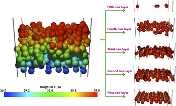
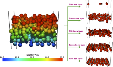
Three monolayers of atoms have been deposited using the evaporation process, simulating ∼6 s of experimental time, where stoichiometric TiO2 is deposited via five TiOx clusters, with low kinetic energy of 1 eV and the argon ion beam when used has higher kinetic energy (40 eV or 100 eV). Figure 1 shows the growth from evaporation deposition without ion-beam assist; notice that the new layers are incomplete, with both oxygen and titanium atoms missing. The low kinetic energy of the arriving atoms does not transfer enough energy into the lattice for much diffusion to occur, therefore leaving the layers incomplete with voids.
Growth of TiO2 at 1 eV deposition energy with no ion-beam assist. The surface is shown, with a breakdown of the newly grown layers. Atoms are coloured by height using the key; titanium atoms are smaller, grey spheres and oxygen atoms are the larger, red spheres. Layers are incomplete as atoms do not have sufficient kinetic energy to mix efficiently during the ballistic phase of the deposition.

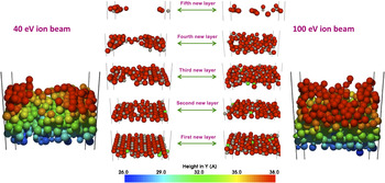
Figure 2 shows the effect of the low- and high-energy ion-beam assistance on the evaporation growth. It is clear that the low-energy ion-beam assist (argon arriving with 40 eV kinetic energy) does not have a significant effect on the growth; layers may be slightly more crystalline as the 40 eV argon depositions introduce more energy into the system, thus allowing slightly more mixing to occur and allowing a more crystalline structure to form over time. Conversely, the higher energy ion-beam assist (argon arriving with 100 eV kinetic energy) introduces too much energy into the system causing damage to the surface, disrupting the crystallinity whilst appearing to densify the film. We also notice implantation of argon deep into the lattice, mainly as a consequence of the higher energy assist. From the experimental results, we expected to see that ion-beam assist would improve film density; however, from our calculations, an increased density effect cannot be definitely concluded as growth has not yet reached a steady state.
Ion-beam assist evaporation growth of TiO2 at 40 eV and 100 eV argon ion energy. Notice that the higher energy ion-beam causes damage to the film, leading to loss of crystallinity, which appears to increase density of the layers in comparison to the lower energy ion-beam. Sub-surface argon atoms are colored in green.

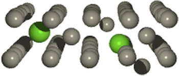
Figure 3 shows positions of the argon within the lattice. We see that argon preferentially sits in one of two locations, either in an interstitial location between titanium layers or as a substitutional atom in a titanium lattice site after knocking the original titanium into a deeper interstitial site. Important here is the impact of argon on the number of titanium interstitials and their penetration depth; the higher energy argon assist creates more titanium interstitials, deeper within the lattice. It has previously been found that the presence of titanium interstitials below an oxygen-rich surface allows an important rutile growth mechanism to occur through the migration of titanium interstitials up to the surface.Reference Vernon, Kenny and Smith16, Reference Wendt, Sprunger, Lira, Madsen, Li, Hansen, Matthiesen, Blekinge-Rasmussen, Lægsgaard, Hammer and Besenbacher20 This growth mechanism is observed throughout all the simulations. However, titanium interstitials deep within the lattice require more time to diffuse upward and thus often remain stuck in the lattice.
The titanium sub-lattice after argon bombardments. Titanium atoms are gray and argon atoms are green. Argon in the lattice sits in one of two sites; either in an interstitial location between titanium layers or as a substitutional defect.

B. Sputter deposition
Four monolayers of atoms have been deposited by simulating magnetron sputtering with a 40 eV deposition energy (an extra layer has been deposited here as this simulation was less computationally expensive). It is possible to bias the substrate to increase the deposition energy, and deposition energies of up to 100 eV were simulated. However, it was found that 100 eV produces too much lattice damage, producing a very incomplete and porous film, and titanium interstitials penetrate as deep as the fourth layer of the substrate (which is too deep for the rutile growth mechanism to work). This would change the optical properties of the film. For this reason, only the 40 eV sputter deposition case is discussed here.
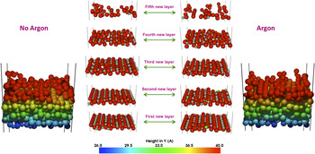
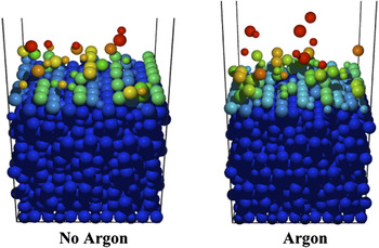
Figure 4 shows a comparison of the growth from deposition of clusters providing stoichiometric TiO2 at 40 eV both ignoring the effect of argon and also including the effects of argon bombardment.
Growth obtained via magnetron sputtering, first without and then with the effect of argon. We assume argon bombardment at 40 eV was as equally probable as the impact of TiOx ad-cluster. Both cases produce highly crystalline growth.

It is clear that in the magnetron sputtering case, argon does not cause any dramatic changes in the quality of growth produced. Experimental results suggest that argon bombardment would improve film density; however, our simulations show no conclusive evidence of this, as growth has not reached a steady state. It is noticeable, however, that when investigating the final position of those atoms from the original substrate (both oxygen and titanium atoms), the simulation which included the argon caused slightly more disruption and damage to the substrate, resulting in more atomic mixing, illustrated below in Fig. 5. The argon bombardment created an increased number of titanium interstitials in the substrate, which would aid the rutile growth mechanism in forming more crystalline rutile; however, a significant difference in growth quality is not evident.
The final positions of those atoms from the original substrate (both oxygen and titanium atoms) colored by height, after deposition of 4 layers. The simulation that included the effect of argon suffered more disruption and damage to the original substrate. Argon bombardment disrupts the surface more than TiOx ad-cluster depositions alone, suggesting that argon should enable or allow more surface mixing and diffusion to occur.

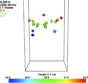
Notice a small number of argon atoms stay implanted within the substrate, illustrated in Fig. 6. The implanted argon sits either in interstitial locations between layers or in titanium lattice sites (shown in the previous section). It is known from Auger electron spectroscopy that 0.5–1.5% of the argon stays within the film.Reference Walls, Hall, Teer and Delcea32 Our simulation models found that 0.09–0.16% of argon remained within the film; however, a steady state has not yet been reached, so it is highly possible that an increased number of argon atoms would become trapped within the lattice as growth continues.
Argon atoms implanted within the film after the magnetron sputtering simulation; 0.09% of argon remains implanted, with ion-beam assisted evaporation we saw up to 0.16% of argon implanted. Atoms are colored by height.

IV. CONCLUSIONS
Otf-KMC combined with traditional MD allows simulation of thin film growth over realistic timescales. In this article, the simulations have modeled ∼6 s of film growth, which using traditional MD would consume millions of computing years.
Evaporation growth, modeled by low energy (∼1 eV) deposition of stoichiometric TiO2 on rutile (110), produces incomplete layers containing voids as there is not enough energy in the system for much diffusion to take place. Low-energy ion-beam assist at 40 eV injected more energy into the system; thus, growth may be slightly more crystalline, although no significant change is observed. The 40 eV argon bombardment created some titanium interstitials in the substrate, thus enabling an important rutile growth mechanism to take place. High-energy ion-beam assist at 100 eV caused disruption and damage to the substrate, resulting in less than perfect crystalline growth, with significant mixing and formation of titanium interstitial deep into the substrate, too deep to be immediately drawn out. A slightly denser film was observed; however, we cannot be certain this is a real effect as growth has not yet reached a steady state, and for deeper insight we would be required to deposit several more layers, which currently is too computationally expensive.
Growth via reactive magnetron sputtering was achieved by simultaneous stoichiometric TiO2 and argon bombardment at 40 eV, the optimal deposition energy to produce dense and almost completely crystalline TiO2. The direct effect of argon bombardment was investigated. It was found that argon bombardment caused an increase in atomic mixing and an increase in titanium interstitials produced; however, this did not seem to have a significant influence on the quality of growth. Argon implantation of around 0.09–0.16% was observed, comparing to the 0.5–1.5% observed experimentally, highlighting that the systems did not reach a steady state growth. It was expected from experimental data that argon bombardment would increase film density; however, in all of our simulations we cannot draw clear conclusions as only three to four monolayers have been deposited, which does not yet put the system in a steady state. Several more monolayers would need to be deposited in order for a steady state to be reached and hence to obtain conclusive evidence for the mechanisms at work on the effect of argon ion bombardment on thin film densification.