Introduction
Independently working, radar and wireless communication systems have been motivated for long time to avoid the potential risks of their integration. The necessity, however, for the coexistence of radio frequency (RF) spectrum among different types of services, urged researchers to start thinking of how to bring radar and wireless communication systems to a common platform. Hence, based on similar waveform designs and front-end architectures of these technologies, researchers get the maximum by integration in terms of cost, size, space, and functional reconfiguration [Reference Han and Wu1].
During the past decade, such an approach for coexistence/unification of these systems has been extensively discussed at different forums based on time, signal, or sub-beam sharing in [Reference Han and Wu1–Reference Shaojian, Bing and Ping4]. In general, this merger of technologies depends on communication based on radar or vice versa [Reference Blunt, Yatham and Stiles5–Reference Guerci8].
In [Reference Han and Wu1], the idea of time-sharing based on time-domain duplexing for integration was proposed. Waveform design for the fusion of an orthogonal frequency division multiplexed (OFDM) signal is considered as a signal sharing mechanism, where the communication signal is transmitted to the intended receiver, while the backscattered signal gets analyzed for radar measurement as in [Reference Sturm and Wiesbeck2, Reference Tigrek, De Heij and Van Genderen3]. Spread spectrum techniques are also analyzed for the joint radar and communication systems (RadCom) [Reference Shaojian, Bing and Ping4]. Moreover, the integration can also occur based on the embedding information bits to the radar echoes. This approach used a tag/transponder, which is located in the coverage area of radar illumination. This tag/transponder is used to remodulate the radar echoes with information bits and then send it back to the desired receiver [Reference Blunt, Yatham and Stiles5]. In spite of the enormous development and much mature radar technology, there is a great potential and demand for techniques that use spectrum in a more intelligent and efficient way between radar and communication systems [Reference Griffiths, Blunt, Cohen and Savy6]. Moreover, the spectrum sharing management for efficient bandwidth utilization of radar and communication systems can play an important role in this field [Reference Biglieri, Goldsmith, Greenstein, Mandayam and Poor7, Reference Guerci8].
In [Reference Hassanien, Amin, Zhang and Ahmad9], the dual function of radar–communication for the unified platform between radar and communication systems needs to identify the priority of both systems based on directivity and power allotment, i.e. between the mainlobe and the sidelobe control. In [Reference Hassanien, Amin and Zhang10], researchers have proposed a principle beamforming weight vector to generate a mainlobe as a primary radar signal, while other weight vectors produced by enforcing the deep null have been used for directed communication purpose.
Likewise, various techniques have been proposed to make this system multifunctional. The concept of Advanced Multifunction Radio Frequency (AMRFC) divides the frequency bands into multiple segments/sub-beams for different purposes, such as radar, communication, and electronic warfare, etc. [Reference Tavik, Hilterbrick, Evins, Alter, Crnkovich, de Graaf, Habicht, Hrin, Lessin, Wu and Hagewood11].
The sub-beam sharing is also introduced in [Reference Quan, Qian, Guq and Zhang12, Reference Li, Li and Li13], where it has been used as an active-phased array radar to integrate radar and communication systems into a unified platform. The drawback of phased array radar is the steering beam angle fixation for all ranges. This limitation is overcome by the frequency diverse array (FDA) radar [Reference Antonik, Wicks, Griffiths and Baker14], which possesses a spatial variation in the signal field pattern due to the range-angle dependence. The concept of FDA was introduced by Antonik in [Reference Antonik, Wicks, Griffiths and Baker14, Reference Antonik, Wicks, Griffiths and Baker15] and has been investigated in the last decade for its applicability in areas such as radar and wireless communication and other applications [Reference Wang16–Reference Khan, Qureshi, Basit, Malik and Umar19]. In an FDA, an array antenna is based on using a small incremental frequency across the array elements, unlike phased array, which uses identical frequencies among all elements within the array. In [Reference Nusenu, Wang and Basit20], authors used spread spectrum sequences and time-modulated frequency diverse multiple-input multiple-output for dual functionality of radar–communication system. The communication embedding is achieved by spread sequence in every radar pulse. In [Reference Nusenu and Wang21], Costas signal waveforms are used to embed information into FDA-multiple-input multiple-output MIMO radar. In [Reference Ji, Chen, Hu, Pan and Shao22], the incremental frequency of FDA has been embedded with information during radar emission.
In [Reference Nusenu, Huaizong, Ye, Xuehan and Basit23], authors used Butler matrix over FDA to transmit a communication signal in the null direction of the radar mainlobe. Moreover, information embedding using spread sequence for every radar pulse and time-modulated FDA with MIMO techniques was proposed in [Reference Nusenu, Wang and Basit24]. Using mainlobe for radar functionalities while transmitting amplitude shift keying (ASK), phase shift keying, and quadrature amplitude modulation (QAM) communication signals in the sidelobe region was investigated in [Reference Ahmed, Zhang and Gu25]. This approach allows the designers to transmit a distinct communication toward different communication receivers available at distinct locations in the sidelobe regions. The drawback of all papers mentioned above, the information embedding took place during radar active mode only, which leads to low throughput/less-achievable data rate. To increase the achievable data rate/throughput, we transmit the communication signal during FDA radar listening mode.
In this paper, we introduce a new approach for dual-function radar–communication systems. The communication waveform transmitted during FDA radar listening mode is used as a secondary function, while keeping the FDA radar functionalities as a primary function in active mode. These two waveforms are transmitted sequentially having two different spatial angles. In other words, radar transmission takes place during the FDA radar active mode, followed by a directed communication transmission during the radar listening mode. The number of transmitted communication uplinks depends on the number of radar pulses transmitted during active mode. At the receiver side, the radar backscattered signal and the communication signal coming from another RadCom during radar listening mode are analyzed. Moreover, we have used orthogonal waveforms for each pulse for better matched filtering at the receiver side. The proposed technique enjoys the bit error rate (BER) improvement, as well as the low probability of interception (LPI) in terms of directional of arrival secrecy and preserves the communication signal toward a specific direction. Furthermore, the performance of the proposed system is analyzed in terms of signal-to-interference ratio (SINR) and Cramer–Rao lower bounds (CRLB) to show its effectiveness.
The rest of this paper is organized as follows. In section “Problem formulation and system model”, we describe the proposed scenario and the system model for dual-function radar–communication DFRC system. Section “Simultaneous signal reception” describes the simultaneous signal reception and the SINR performance analysis for both systems. Section “Simulation result” provides simulation results and discussions, and section “Conclusion” concludes the paper and discusses the future directions.
Problem formulation and system model
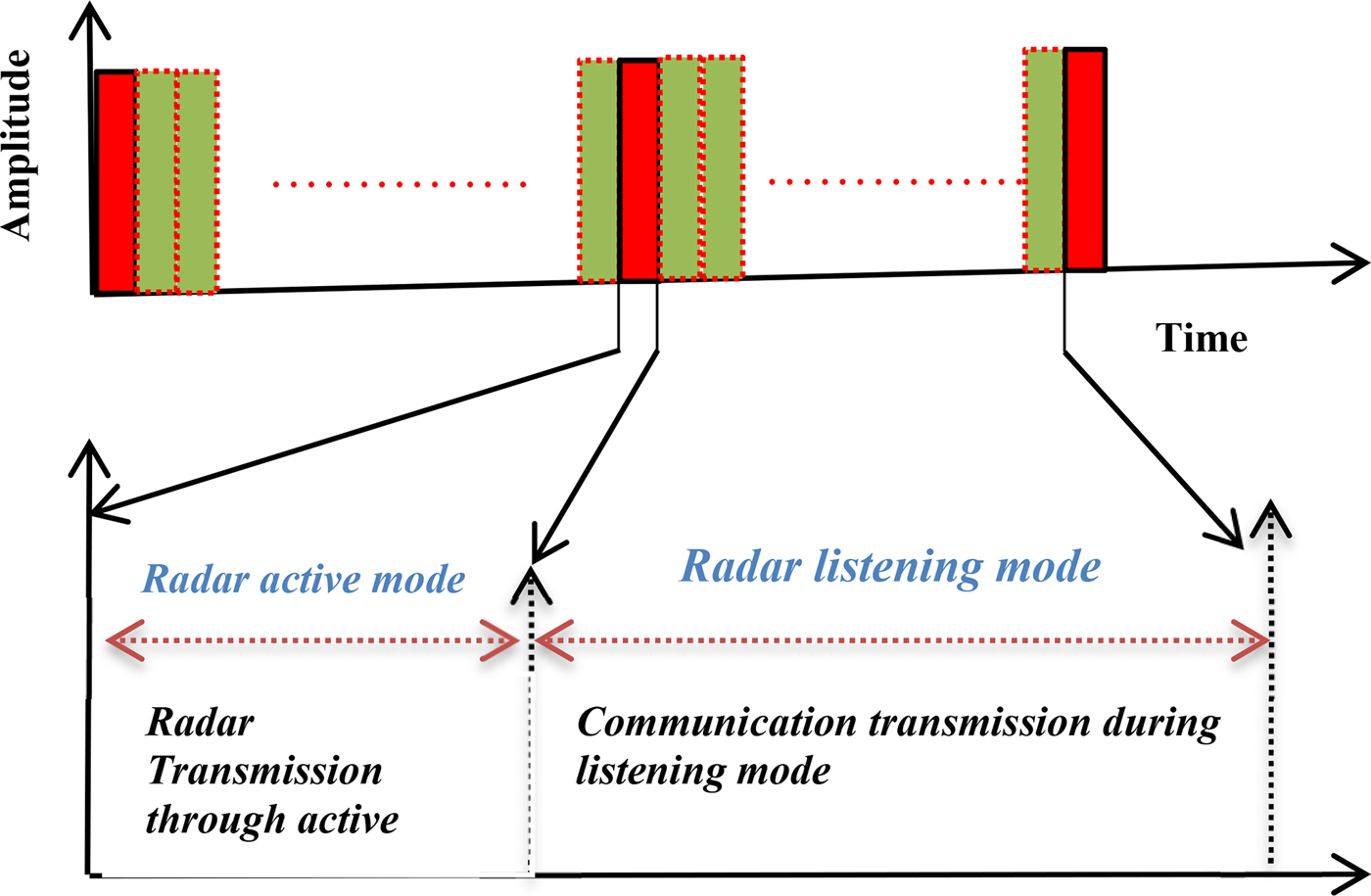
In conventional radar system, the radar transmits energy for only a small period during each pulse repetition interval (PRI), and then keeps silent with no transmission known as radar listening time, as shown in Fig. 1 and expressed as
 $$T_t = t_b + T_s,$$
 $$T_s = T_t-t_b,$$
wheret b is the radar pulse width, T s is the radar listening time mode, and T t is the total time.
Modes transmission diagram for the proposed joint radar–communication systems.

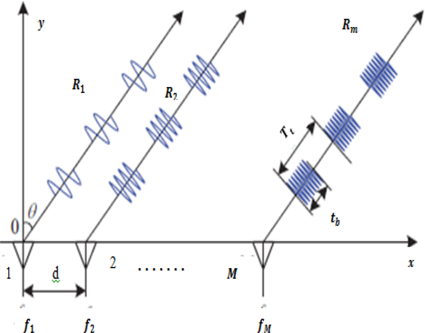
In our scenario, we consider two joint radar and communication systems (RaC1 and RaC2) shown in Fig. 2. Each RaC performs a dual function of radar–communication systems by transmitting a radar pulse during its active mode and communication signal during its listening mode. Two colocated receivers with N elements are placed close to their respective transmitters, RaC1 and RaC2. When RaC1 sends a radar pulse toward a far-field target, the echo received by the RaC1 receiver is match-filtered to extract the radar measurements. On the other hand, the communication signal coming from RaC2 toward the RaC1 receiver will be detected as the desired communication signal, while the radar echo coming from RaC2 is considered as the interference to the RaC1 receiver. We have used orthogonal waveforms for each pulse for better matched filtering at the receiver side.
The proposed scenario for joint FDA radar–communication systems.

Consider an FDA radar with M elements and uniform spacing d shown in Fig. 2. The radar radiated waveform by the m th element during one PRI is transmitted toward a spatial direction Θ ∈ [θ min, θ max] and range bin R ∈ [R min, R max]. The communication waveform corresponds to a spatial region $\; {\bar \Theta} \in \lsqb {\; {{\bar \theta}}_{\min}, {{\bar \theta}}_{\max}} \rsqb $ and the range bin
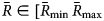 ${\bar R}\in [{\bar R}_{\min} \,{\bar R}_{\max} $. These two waveforms can be represented in a general form as two functions in the time domain in the following expression.
 $$s(t) = \left\{ {\matrix{ {s_1(t,r_0,\theta_0)} & {0 \le t \le t_b} \cr {} & {\Theta :\theta_{\min} \le \theta_0 \le \theta_{\max}} \cr {} & {R:R_{\min} \le r_0 \le R_{\max}} \cr {s_2(t,r_c,\theta_c} & {t_b \lt t \le T_s} \cr {} & {{\bar \Theta} :{{\bar \theta}}_{\min} \le \theta_c \le {{\bar \theta}}_{\max}} \cr {} & {{\bar R}:{{\bar R}}_{\min} \le r_c \le {{\bar R}}_{\max}} \cr}} \right\},$$
where s 1(t, r 0, θ 0)is the baseband representation of the FDA radar during the active mode, and s 2(t, r c, θ c) denotes the communication baseband transmitted signal during the listening time mode of FDA radar.
The radiated waveform from the m th element can be expressed as
 $$X_m\lpar t \rpar = {\bf w}_{m\; \;} ^H \,e^{\,j2\pi f_mt},$$
where f m = f 1 + (m − 1) Δf, f m is the respective frequency from the m th element of FDA radar, f 1is the reference frequency, and Δf is the incremental frequency and  $w_{m\; \;} ^H \; $ is the weighting function pattern to a specific range r 0 and angle θ 0 given as [Reference Wang, Shao and Cai26]
 $$w_{m\;} ^H = e^{\,j2\pi f_m\; \lpar {(r_0/c)-(md\sin \theta_0/c)} \rpar },$$
where d is the element spacing, c is the speed of light. The arrived signal at the target may be expressed as
 $$\eqalign{s_1\lpar t \rpar = &\mathop \sum \limits_{m-1}^M X_m\left( {t-\displaystyle{{r_m} \over c}} \right)\; = \mathop \sum \limits_{m = 1}^M {\bf w}_{m\; \;} ^H \; e^{\,j2\pi \; f_m\lpar {t-(r_m/c)} \rpar }\; \cr = &\sum\nolimits_{m = 1}^M {\bf w} _{m\; \;} ^H \; e^{\,j2\pi \; f_m\lpar {t-\; (r/c) + (md\sin \theta /c)} \rpar }} $$
and
 $$\; r_m = r-md\,\sin \theta \;, $$
where r is the slant range between the reference element and the target, and θ is the direction angle.
Equation (6) can be written as
 $$\eqalign{s_1\lpar t \rpar = &\mathop \sum \limits_{m = 1}^M \; e^{\,j2\pi \,f_mt}e^{-j2\pi \,f_m} \cr &\left[ {\left( {\; \displaystyle{{r-r_0} \over c}} \right)} \right.\left. {-\displaystyle{{md} \over c}\; \lpar {\sin \theta -\sin \theta_0} \rpar } \right].} $$
For a far-field target, equation (8) can be written as
 $$\eqalign{s_1\lpar t \rpar = &e^{\,j2\pi \,f_1t}e^{-j\Psi f_1}\; \mathop \sum \limits_{m = 1}^M \lpar {e^{-j\Delta f\Psi}} \rpar ^{m-1} \cr = &\; e^{\,j2\pi \,f_1t}e^{-j\Psi f_1}\,e^{-j\lpar {M-1} \rpar (\Psi /2)}\left( {\displaystyle{{\sin \lpar {(M\Delta f\Psi )/2} \rpar } \over {\sin \lpar {(\Delta f\Psi )/2} \rpar }}} \right)\;,} $$
where
 $$\Psi = 2\pi \left[ {\left( {\; \displaystyle{{r-r_0} \over c}} \right)-\displaystyle{d \over c}\; \lpar {\sin \theta -\sin \theta_0} \rpar } \right].$$
By putting (10) into (9), it can be further written as
 $$\eqalign{s_1\lpar t \rpar\,=& e^{\,j2\pi \,f_1t}e^{-j\Psi f_1}\,e^{-j\lpar {M-1} \rpar (\Psi /2)} \cr & \times \left[ {\displaystyle{{\sin (M\pi \Delta f\lpar {\; (r-r_0/c)} \rpar\!-\!\lpar {\; (\pi \Delta fd)/c} \rpar \; \lpar {\sin \theta -\sin \theta_0} \rpar } \over {\sin (\pi \Delta f\lpar {\; (r-r_0)/c} \rpar\!-\!\lpar {\; (\pi \Delta fd)/c} \rpar (\sin \theta -\sin \theta_0)}}} \right].} $$
FDA transmit beam forming during radar active mode
Consider the FDA structure shown in Fig. 3. The phase of the signal transmitted from the reference element (first element) to a far-field target given in [Reference Wang, Shao and Cai26] as
 $$\gamma _1 = \; \displaystyle{{2\pi f_1\; r} \over c}\; \;, $$
where r is the target range from the first element. Similarly, the phase of the signal radiated from the second element can be written as
 $$\gamma _2 = \; \displaystyle{{2\pi f_2\; r_2} \over c} = \displaystyle{{2\pi (\,f_1 + \Delta f)\lpar {r-md\,\sin \theta} \rpar } \over c}\; \;. $$
FDA array elements.

We calculate the difference between the two elements as
 $$\eqalign{\gamma _2-\gamma _1 = &\displaystyle{{2\pi f_2r_2} \over c} = \displaystyle{{2\pi (\,f_1 + \Delta f)\lpar {r-md\,\sin \theta} \rpar } \over c}-\displaystyle{{2\pi f_1r} \over c} \cr = &\displaystyle{{-2\pi f_1d\,\sin \theta -2\pi \Delta fd\,\sin \theta} \over c}-\displaystyle{{2\pi \Delta fr} \over c}.} $$
Likewise, the difference between the m th and the reference elements can be given as
 $$\eqalign{\gamma _m-\gamma _1 = \gamma _{m-1} = &-\displaystyle{{2\pi f_1\lpar {M-1} \rpar d\,\sin \theta} \over c} \cr &-\displaystyle{{2\pi \lpar {M-1} \rpar \Delta fr} \over c}\;.} $$
For a given target at far field, the transmit steering vector can be represented as
 $${\bf a}_{\bf \Theta} \lpar {\theta, r} \rpar = \left[ {\matrix{ {1\; e^{-j\lpar {((2\pi fd\sin \theta )/c) + ((2\pi \Delta fd\sin \theta )/c)-((2\pi \Delta fdr)/c)\;} \rpar } \ldots..} \cr { \ldots e^{-j\lpar {((2\pi f\,(M-1)d\sin \theta )/c)-((2\pi \lpar {M-1} \rpar \Delta fr)/c)\;} \rpar }} \cr}} \right]^T$$
 $$\eqalign{ = &\lsqb {1\; \,e^{-j\lpar {((2\pi fd\sin \theta )/c) + ((2\pi \Delta fd\sin \theta )/c)\;} \rpar } \ldots \ldots \ldots e^{-j\lpar {(2\pi f\,(M-1)d\sin \theta )/c} \rpar }} \rsqb ^T \cr &\odot \lsqb {1\,e^{\,j\lpar {(2\pi \Delta fdr)/c\;} \rpar } \ldots \ldots \ldots \; e^{\,j\lpar {(2\pi (M-1)\Delta fdr)/c\;} \rpar }} \rsqb ^T \cr = &{\bf a}_{\rm \Theta} \lpar {\theta, r} \rpar = {\bf a}_\Theta \lpar \theta \rpar \odot {\bf a}_R\lpar r \rpar \;,} $$
where  $\odot $ is the Hadamard product. The beampattern toward direction θ 0 and range r 0 can be written as
 $$s_1\lpar {t,\theta_0,r_0} \rpar = \; [{\bf w}^H{\bf a}_\Theta \lpar {\theta_0,r_0} \rpar ]\phi _1\lpar t \rpar,$$
where ϕ 1(t) is the orthogonal waveform associated with the radar signal to help for better detection at the receiver side,  ${\bf w}^H$ is the radar weighting vector.
Suppose another radar transmitter from RaC2 located at aΘ (θ i, r i) is radiating a pulse toward the same target of RaC1, which is located at (θ 0, r 0). The echo arriving from RaC2 is assumed to be the interference to the radar receiver of RaC1. The beampattern of RaC2 in an interference direction θ i and range r i can be written as
 $$s_3\lpar {t,\theta_i,r_i} \rpar = [{\bf w}^H{\bf a}_\Theta \lpar {\theta_i,r_i} \rpar ]\phi _3\lpar t \rpar,$$
where ϕ 3(t) is the orthogonal waveform associated with the radar signal radiated from RaC2.
FDA-OFDM communication during radar listening mode
In the proposed system, the communication transmission takes place during FDA radar listening mode; the communication signal used in this scenario is the FDA-OFDM which is produced from FDA elements. This signal sent to the intended receiver located at a predefined communication direction given in [Reference Ding, Zhang and Fusco17] as
 $$\eqalign{s_2\lpar t \rpar = &\mathop \sum \limits_{m = 1}^M {\bf b}_m^H \,e^{\,j2\pi \,f_m\lpar {t-(r_m/C)} \rpar }\,e^{-j\varphi _m} \cr = &\mathop \sum \limits_{m = 1}^M {\bf b}_m^H \,e^{\,j2\pi \,f_mt}\,e^{-j\lsqb {2\pi \,f_m\lpar {(r-md\,\sin \theta )/C} \rpar + \varphi_m\; \;} \rsqb },} $$
where b m is the information bit, and φm is the initial phase of the m th RF carrier.
The FDA-OFDM signal could gain a low probability of intercept by setting the summation for each m along the predefined direction to be a constant value Φm given as [Reference Ding, Zhang and Fusco17]
 $$\Phi _m = 2\pi f_m\lpar {r-md\,\sin \theta_c/c} \rpar + \varphi _m.$$
The dynamic mapping needs to be updated dynamically to satisfy the condition in (20) along the intended angle. By doing so, the OFDM will be preserved along θ c which will be distorted in other directions, which leads to safety against any eavesdropper or interceptor. Therefore, (19) can be written as
 $$s_2\lpar t \rpar = \mathop \sum \limits_{m = 1}^M {\bf b}_m^H \,e^{\,j2\pi \,f_mt}\,e^{-j\Phi _{m\;}}. $$
Moreover, we can write (21) in a vector form as
 $$s_2\lpar t \rpar = \left[ {\matrix{ {b_1} & {b_2} & {b_3} & {..b_m} \cr}} \right]\left[ {\matrix{ 1 \cr {\matrix{ {ej2\pi ft} \cr {e^{\,j2\pi \,f_2t}} \cr {e^{\,j2\pi \,f_3t}} \cr. \cr. \cr}} \cr {\; e^{\,j2\pi \lpar {M-1} \rpar \; f_mt}} \cr}} \right]e^{-j\Phi _m}.$$
In FDA, the incremental frequencies among element arrays make the array radiation changes as a function of angle, range, and time [Reference Nusenu and Basit27, Reference Nusenu, Chen, Wang, Ji and Opuni-Boachie28]. By doing so, if the communication signal transmitted toward a specific angle, then the FDA still has different ranges. Hence, even if the eavesdropper and communication user are located in the same direction, they will still have different ranges. Moreover, authors in [Reference Nusenu, Chen, Wang, Ji and Opuni-Boachie28] investigated the superiority of the FDA communication performance over the phased array communication in terms of range dimension. In our paper, we investigate the FDA-OFDM communication transmission signal to a predefined direction to protect our transmitted signal from any eavesdropper located outside the intended direction as in [Reference Ding, Zhang and Fusco17]. This is clear in equation (21), where the intended signal can only be obtained by the concern receivers available along the direction of the desired communication transmission. The FDA-OFDM hybridization allows the transmission of distinct carriers through FDA elements toward the desired range-angle position (θ c, r c) and enhances the probability of interception reduction.
For a receiver located at far field, the transmitted steering vector for communication purpose may be expressed as
 $${\bf a}_{{\bar \Theta}} \lpar {\theta, r} \rpar = {\bf a}_{{\bar{\bf \Theta}}} \lpar {\theta_c} \rpar \odot {\bf a}_{{\bar R}}\lpar {r_c} \rpar,$$
where
 $$\eqalign{& {\bf a}_{\bar{\Theta }}\left( {\theta _c} \right) = \left[ {1\quad e^{-j\left( {((2\pi fd\sin \theta _c)/c) + ((2\pi \Delta fd\sin \theta _c)/c)\; } \right)}} \right. \cr & \quad \left. { \ldots \ldots \ldots e^{-j\left( {(2\pi f\left( {M-1} \right)d\sin \theta _c)/c} \right)}} \right]^{\rm T}}$$
 $${\bf a}_{{\bar R}}\lpar {r_c} \rpar = \; \lsqb {1\quad e^{\,j\lpar {(2\pi \Delta fdr_c)/c\;} \rpar } \ldots \ldots \ldots \; e^{\,j\lpar {(2\pi \lpar {M-1} \rpar \Delta fdr_c)/c\;} \rpar }} \rsqb ^T\;. $$
By applying the orthogonal waveforms ϕ 2(t) and ϕ 4(t) to the baseband transmitted communication signals from RaC1 and RaC2, respectively, toward a specific angle θ c and range r c, the equations may be written as
 $$s_2\lpar {t,\theta_c,\; r_c} \rpar = \lsqb {{\bf b}^H{\bf a}_{{\bar{\bf \Theta}}} \lpar {\theta_c,r_c} \rpar } \rsqb \phi _2\lpar t \rpar {\rm \;,} $$
 $$s_4\lpar {t,r_c,\theta_c} \rpar = \lsqb {{\bf b}^H{\bf a}_{{{\bar {\rm \Theta}}}} \lpar {\theta_c,r_c} \rpar } \rsqb \phi _4\lpar t \rpar {\rm \;,} $$
where ϕ 2(t) and ϕ 2(t) are the orthogonal waveforms associated with the communication signals for better matched filtering at the receiver side.
Simultaneous signal reception
We assume that the receiver elements are closely located to the RaC1 and RaC2 transmitters such that both transmitters and receivers look at the same spatial angle from the far-field point. The total received signal at the first receiver of RaC1 will be the combination of radar and communication signals and is modeled as
 $$x\lpar t \rpar = r_{d-{\rm echo}}\lpar t \rpar + r_i\lpar t \rpar + c\lpar t \rpar + n\lpar t \rpar,$$
where r d−echo(t) is the radar desired echo,r i(t) is the interference echo transmitted from RaC2, c(t) is the communication signal, and n(t) is the additive white noise vector with zero mean.
Radar received signal analysis
At radar receiver, the downlink communication signal is considered as the interference to the incoming radar echo and vice versa. The total received signal by the RaC1 receiver may be expressed as
 $$\eqalign{x\lpar t \rpar = \,&\alpha _0\lsqb {{\bf w}^H{\bf a}_{\bf \Theta} \lpar {\theta_0,r_0} \rpar } \rsqb {\bf v}_\Theta \lpar {\theta_0,r_0} \rpar \phi _1\lpar t \rpar \cr & + \alpha _{\rm {\frak i}}\lsqb {{\bf w}^H{\bf a}_i\lpar {\theta_i,r_i} \rpar } \rsqb {\bf v}_i\lpar {\theta_i,r_i} \rpar \phi _3\lpar t \rpar \cr & + \alpha _c\lsqb {{\bf b}^H{\bf a}_{{\bar \Theta}} \lpar {\theta_c,r_c} \rpar } \rsqb {\bf v}_{{\bar \Theta}} \lpar {\theta_c,r_c} \rpar \phi _4\lpar t \rpar + n\lpar t \rpar,} $$
Here, $ {\bf v}_\Theta \lpar {\theta_0,r_0} \rpar $ is the receive steering vector of the desired radar echo,
 $ {\bf v}_i\lpar {\theta_i,r_i} \rpar $ is the receive steering vector of the interferer echo transmitted from another radar (in this example RaC2 transmitter),
 $ {\bf v}_{{\bar \Theta}} \lpar {\theta_c,r_c} \rpar $ is the receive steering vector of the communication signal coming from RaC2. The parameters α 0, α 𝔰i, α c are the complex amplitudes of the received radar, interference, and communication signals. In this regard, each of the received signals has its own orthogonal waveform ϕ(t). These signals (radar echo, communication, and interference signals) are considered as the interference to each other, and they are depending on their own orthogonal waveforms transmitted with them by the RaC transmitter arrays. These orthogonal waveforms are designed at the transmitter to help in better detection and separation of the received desired signals at the receiver side. Therefore, the first two terms in (28) are radar signal dependent. They depend on the signals radiated by the joint platform and backscattered by targets and clutters as well as they depend on their corresponding orthogonal waveforms. Using the matched filter, the received radar desired echo to the transmitted signal ϕ 1(t) may be written as
 $$\eqalign{Y_0\lpar t \rpar = &\displaystyle{{\mathop \int \nolimits_{t_b} \; x\lpar t \rpar \phi _1^{^\ast} \lpar t \rpar \,dt} \over {\mathop \int \nolimits_{t_b} {\vert {\phi_1^{^\ast} \lpar t \rpar } \vert } ^2\,dt}} \cr = &\alpha _0\lsqb {{\bf w}^H{\bf a}_\Theta \lpar {\theta_0,r_0} \rpar } \rsqb {\bf v}_\Theta \lpar {\theta_0,r_0} \rpar \cr & + n_{i + n},} $$
where t b is the pulse width duration, and (n i+n) is the interference and noise observed by the radar receiver and can be written as
 $$\eqalign{n_{rad\lpar {i + n} \rpar } = &c\lpar t \rpar + r_{\rm {\frak i}}\lpar t \rpar + n\lpar t \rpar \cr = &\alpha _{\bf {\frak i}}\lsqb {{\bf w}^H{\bf a}_i\lpar {\theta_i,r_i} \rpar } \rsqb {\bf v}_i\lpar {\theta_i,r_i} \rpar \phi _3\lpar t \rpar \cr & + \alpha _c\lsqb {{\bf b}^H{\bf a}_{{\bar{\bf \Theta}}} \lpar {\theta_c,r_c} \rpar } \rsqb {\bf v}_{{\bar{\bf \Theta}}} \lpar {\theta_c,r_c} \rpar \phi _4\lpar t \rpar + n\lpar t \rpar,} $$
 $$ \eqalign{\hskip +-52pt n_{rad\lpar {i + n} \rpar } = \alpha _{\bf {\frak i}}{\bf u}\lpar {\theta_i,r_i} \rpar + \alpha _c{\bf u}\lpar {\theta_c,r_c} \rpar + n\lpar t \rpar,$$
where  ${\bf u}\lpar {\theta_i,r_i} \rpar $ is the respective virtual steering vector defined as
 $\lsqb {{\bf w}^H{\bf a}\lpar {\theta, r} \rpar } \rsqb {\bf v}_\Theta \lpar {\theta, r} \rpar \phi _3\lpar t \rpar $ and
 ${\bf u}\lpar {\theta_c,r_c} \rpar $ is the respective virtual steering vector defined as
 $\lsqb {{\bf b}^H{\bf a}_{{\bar \Theta}} \lpar {\theta_c,r_c} \rpar } \rsqb {\bf v}_{{\bar{\bf \Theta}}} \lpar {\theta_c,r_c} \rpar \phi _4\lpar t \rpar $. We assume that the additive white Gaussian noise vector with zero mean is δ 2I.
The FDA radar transmit/receive beampattern in [Reference Wang, Shao and Cai26] is given as
 $${\bf G}_{\bf \Theta} \lpar {\theta, r} \rpar = \displaystyle{{ {\vert {{[\; {\bf a}_{\rm \Theta} \lpar \theta \rpar .{\bf a}_\Theta \lpar r \rpar ]}^H {\bf a}_\Theta \lpar {\theta_0} \rpar .{\bf a}_\Theta \lpar {r_0} \rpar } \vert } ^2} \over {{\vert { {\bf a}_\Theta \lpar {\theta_0} \rpar \; \; \; {\bf a}_{\bf \Theta} \lpar {r_0} \rpar } \vert } ^4}}.$$
The covariance matrix for the radar received signal is
 $$\eqalign{C_{0\lpar {i + n} \rpar } = &\alpha _i^2 \lsqb {u\lpar {\theta_i,r_i} \rpar {\bf u}^H\lpar {\theta_i,r_i} \rpar } \rsqb \cr & + \alpha _c^2 \lsqb {{\bf u}\lpar {\theta_c,r_c} \rpar {\bf u}^H\lpar {\theta_c,r_c} \rpar } \rsqb + \delta ^2I.} $$
The output of SINR for FDA radar is given in [Reference Wang, Shao and Cai26] as
 $${\rm SIN}{\rm R}_{{\rm radar}} \triangleq \displaystyle{{\delta ^2{\vert {{\bf u}_\Theta^H \lpar {\theta_0,r_0} \rpar {\bf u}_\Theta \lpar {\theta_0,r_0} \rpar } \vert } ^2} \over { {\bf u}_\Theta ^H \lpar {\theta_0,r_0} \rpar C_{0\lpar {i + n} \rpar }{\bf u}_\Theta \lpar {\theta_0,r_0} \rpar }}.$$
To investigate the performance of the received signal after matched filtering as in (29), we consider a target present at (θ 0, r 0). In case the range is known and the angle is unknown, the corresponding CRLB is equivalent to the inverse of Fisher information matrix (FIM) and has been given in [Reference Wang and Shao29] as
 $$\eqalign{{\rm CRL}{\rm B}_{{\rm angle}} = &{\bf \Gamma }^{-1} \cr = &\displaystyle{1 \over \matrix{8\pi ^2d^2\sin ^2\left( \theta \right).{\rm SNR}\; \left\{ {\displaystyle{{\mathop \sum \nolimits_n^{N-1} {\left( {n-1} \right)}^2} \over {\lambda ^2}}} \right.\; \hfill \cr \left. {\quad \quad + \displaystyle{{{\rm \Delta }f^2\mathop \sum \nolimits_n^{N-1} {\left( {n-1} \right)}^4} \over {c^2}} + \displaystyle{{2{\rm \Delta }f\mathop \sum \nolimits_n^{N-1} {\left( {n-1} \right)}^3} \over {\lambda c}}} \right\} \hfill} },} $$
where Γ−1 is the inverse FIM. In [Reference Ji, Chen, Hu, Pan and Shao22], the radar emission contains information bits which limit the CRLB for an angle to some extent and keeps the FDA RadCom fluctuating between FDA and phased array systems, because whenΔf is multiplied with binary information “one” it gives FDA system and when multiplied with binary information “zero” it gives phased array system, so this approach keeps the system performance in between both conventional systems. Therefore, they bound the CRLB for an angle to a certain value only such as
 $${\rm CRLB}_{{\rm angle}}^{{\rm Lower}\,{\rm bound}} \lt {\rm CRL}{\rm B}_{{\rm FDA}\,{\rm radcom}} \lt {\rm CRLB}_{{\rm angle}}^{{\rm Upper}\,{\rm bound}}. $$
In contrast, our proposed system allows the CRLB to be achieved without any deterioration, exactly like the conventional FDA conventional system. In case the angle is a known parameter and we need to estimate the range parameter, the CRLB is again the inverse of FIM of range (r 0) and defined as
 $${\rm CRL}{\rm B}_{{\rm range}} = {\bf \Gamma} ^{-1} = \displaystyle{1 \over {8\pi ^2.{\rm SNR}\; \left\{ {\displaystyle{{{\rm \Delta} f^2\mathop \sum \nolimits_n^{N-1} {\lpar {n-1} \rpar }^2} \over {c^2}}} \right\}\;}} \;. $$
Hence the information embedding in [Reference Ji, Chen, Hu, Pan and Shao22] has no significant influence on the range, but our system gives an identical result to the FDA conventional system.
Communication downlink signal analysis
In contrast, for communication receiver, the total received signal at the RaC1 receiver can be expressed as
 $$x\lpar t \rpar = \alpha _c\lsqb {{\bf b}^H{\bf a}_{{{\bar {\rm \Theta}}}} \lpar {\theta_c,r_c} \rpar } \rsqb {\bf v}_{{{\bar {\rm \Theta}}}} \lpar {\theta_c,r_c} \rpar \phi _4\lpar t \rpar + r\lpar t \rpar + n\lpar t \rpar,$$
where r(t) is the radar echo/echoes. Here the radar echo and noise are considered to be the interference to the detected communication signal. Using the matched filter, the received signal to the transmitted ϕ 4(t) may be written as
 $$\eqalign{Y_c\lpar t \rpar = &\displaystyle{{\mathop \int \nolimits_{t_b} x\lpar t \rpar \phi _4^{^\ast} \lpar t \rpar dt} \over {\mathop \int \nolimits_{t_b} {\vert {\phi_4^{^\ast} \lpar t \rpar } \vert } ^2dt}} \cr = &\alpha _c\lsqb {{\bf b}^H{\bf a}_{{{\bar {\rm \Theta}}}} \lpar {\theta_c,r_c} \rpar } \rsqb {\bf v}_{{{\bar {\rm \Theta}}}} \lpar {\theta_c,r_c} \rpar \cr & + n_{i + n\;}.} $$
The interference and the noise observed by the communication receiver point of view is
 $$\eqalign{n_{{\rm com}\lpar {i + n} \rpar } = &r\lpar t \rpar + n\lpar t \rpar \cr = &\alpha _{\bf {\frak i}}\lsqb {{\bf w}^H{\bf a}_{\rm \Theta} \lpar {\theta_{\rm {\frak i}},R_{\rm {\frak i}}} \rpar } \rsqb {\bf v}_{\rm \Theta} \lpar {\theta_{\rm {\frak i}},R_{\rm {\frak i}}} \rpar \phi _{\rm {\frak i}}\lpar t \rpar + n\lpar t \rpar \cr = &\alpha _{\bf {\frak i}}{\bf u}\lpar {\theta_i,R_i} \rpar + n\lpar t \rpar,} $$
where  $u\lpar {\theta_i,R_i} \rpar = \lsqb {{\bf w}^H{\bf a}_{\bf \Theta} \lpar {\theta_{\rm {\frak i}},R_{\rm {\frak i}}} \rpar } \rsqb {\bf v}_{\rm \Theta} \lpar {\theta_{\rm {\frak i}},R_{\rm {\frak i}}} \rpar \phi _{\rm {\frak i}}\lpar t \rpar .$ The covariance matrix for the communication received signal is
 $$C_{c\lpar {i + n} \rpar } = \delta ^2\lsqb {{\bf u}_{{{\bar {\rm \Theta}}}} \lpar {\theta_c,R_c} \rpar } \rsqb {\bf u}_{{{\bar {\rm \Theta}}}} ^H \lpar {\theta_c,R_c} \rpar + \delta ^2I.\; $$
The output of SINR for communication is given as
 $${\rm SIN}{\rm R}_{{\rm com}} \triangleq \displaystyle{{\delta ^2{\vert {{\bf u}_{\rm \Theta} {\lpar {\theta_c,R_c} \rpar }^H{\bf u}_{\rm \Theta} \lpar {\theta_c,R_c} \rpar } \vert } ^2} \over { {\bf u}_{{{\bar {\rm \Theta}}}} ^H \lpar {\theta_c,R_c} \rpar C_{c\lpar {i + n} \rpar }{\bf u}_{{{\bar {\rm \Theta}}}} \lpar {\theta_c,R_c} \rpar }} {\rm.} $$
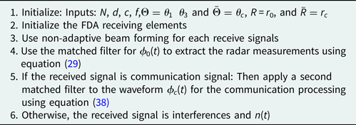
To summarize section “Simultaneous signal reception”, the received waveform steps can be concluded as in Table 1.
Algorithm

Finally, we analyze the link budget of our proposed system of joint radar and communication system based on silent mode. In our proposed system, the maximum radar range is an important parameter. Let the distance between joint radar–communication receivers denoted as d max. The link budget for maximum radar range can be calculated as given in [Reference Gaglione, Clemente, Ilioudis, Persico, Proudler, Soraghan and Farina30] as
 $$\eqalign{r_{{\rm max}} = &\left( {\displaystyle{{P_tG_{t,\,{\rm radar}}G_{r,\,{\rm radar}}} \over {{\rm \;\;} \tau \,{\rm PRF}\,F_{{\rm radar}}}}} \right. \left. { \times \displaystyle{\rho \over {(4\pi^3)}} \displaystyle{{\lambda^2L_{{\rm loss}}} \over { k_0B_w{\rm SN}{\rm R}_r}}n^{0.5}{\rm Gsp}} \right)^{1/4}.} $$
From the above equation, the radar receives echo signal power inversely proportional to the 4th power of distance, while in communications this becomes stronger and it goes to 2nd power. The communication link budget can be given as
 $$\eqalign{d_{{\rm max}} = &\left( {\displaystyle{{P_tG_{t,\,{\rm comm}}G_{r,\; \,{\rm comm}}} \over {{\rm \;\;} \tau \; \,{\rm PRF}\,F_{{\rm comm}}}}} \right. \left. { \times \displaystyle{\rho \over {(4\pi^3)}} \displaystyle{{\lambda^2L_{{\rm loss}}} \over { k_0B_w\,{\rm SN}{\rm R}_r}}} \right)^{1/2},} $$
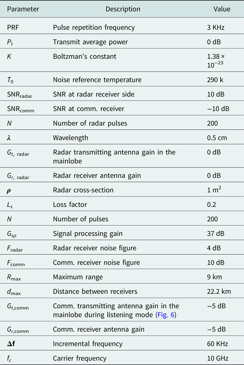
where d max is the maximum radar–communication receiver distance. The link parameters are listed in Table 2 below.
Link budget parameters

Simulation result
In this section, we performed an extensive simulation to illustrate the performance features of the proposed scheme.
Example 1. Communication performance within radar active mode:
For the sake of comparison between the behavior of communication transmissions during the radar active and listening modes. We have first proposed a communication transmission via radar sidelobes during the active mode to show the simultaneous operation for dual-function radar–communication system. We synthesized the power radiation toward the target and proposed four communication directions in the sidelobe region. We consider 11 elements at the FDA transmitter with the same number at the receiver side and all elements having a half wavelength spaced antenna apart. In this example, we use an optimization problem for the simultaneous transmission of desired radar waveform in the mainlobe (as a primary function) and communication waveform in the sidelobe region (as a secondary function) is given by the following expressions:
 $$\matrix{ {{\rm min}} \cr {{\bf w}_1} \cr} \matrix{ {{\rm max}} \cr \theta \cr} \vert {{\bf w}_1^{^H} {\bf a}\lpar \theta \rpar } \vert \; \; \;, $$
 $${\rm s}.{\rm t\;} \,\,\,{\bf w}_1^H {\bf a}\lpar {\theta_{{\rm radar}}} \rpar = 1,\,\,\theta _t\in \Theta \; {\rm \;,} $$
 $${\bf w}_1^H {\bf a}\lpar {\theta_{ci}} \rpar = \Delta _{i\;} \,\,{\rm for}\,1 \le i \le k-1.$$
In the above expressions,  ${\bf w}_1$ is the M × 1 weight vector,
 ${\bf a}\lpar {\theta_t} \rpar $ is the M × 1 steering vector toward the target at θ radar in the radar spatial sector θ,
 ${\bf a}\lpar {\theta_{ci}} \rpar $ is the M × 1 steering vector toward a pre-defined i th communication receiver at angle (θ ci).
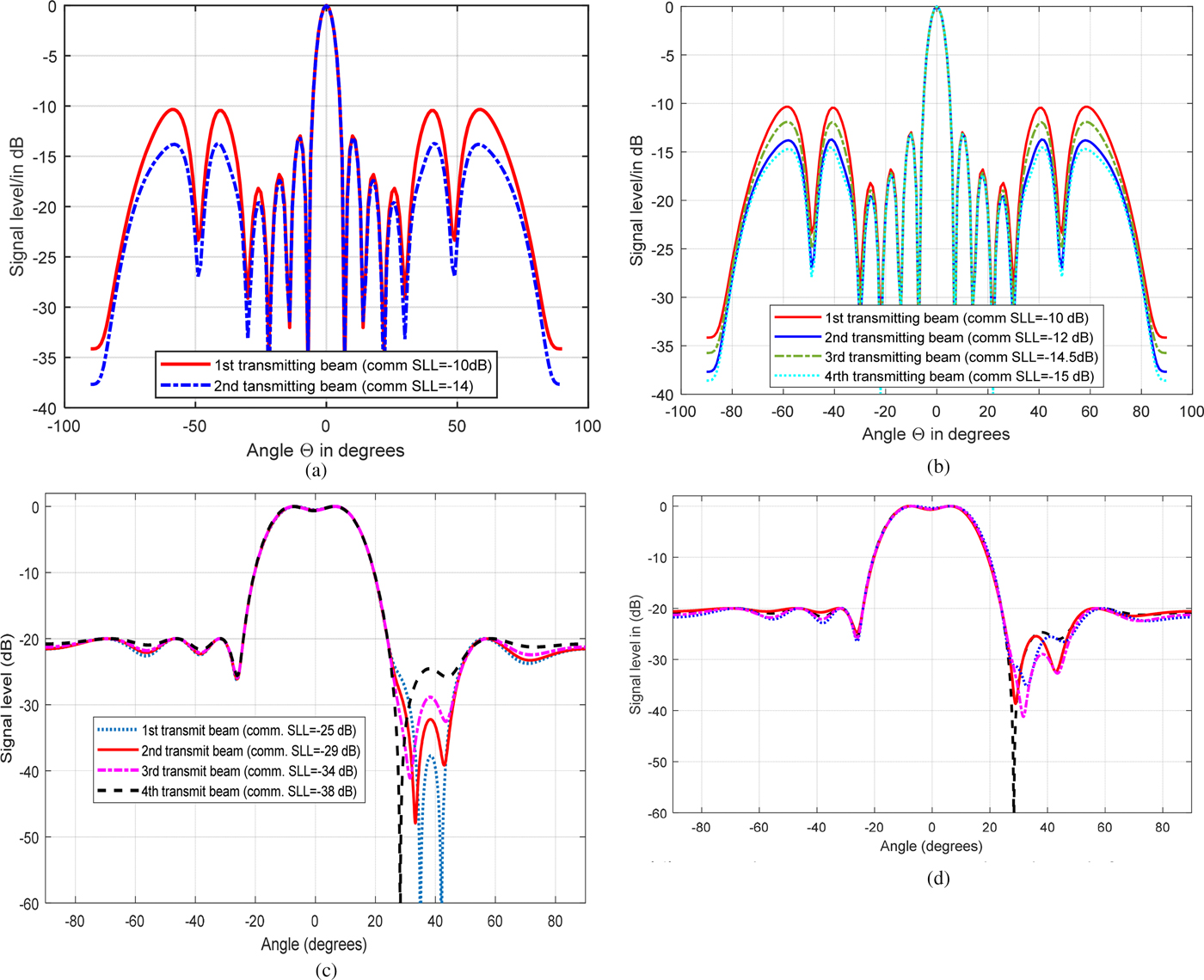
For communication purpose, we changed the sidelboe level by changing the sidelobe power and kept the radar beam with unity power. The power of the two transmitted beampatterns of the mainlobe assumed to be directed toward a radar target at θ radar = 0°, and four communication receivers assumed to be located at θ c1 = −60°, θ c1 = −40°, θ c3 = 40°, and θ c4 = 60°, respectively. The variation of sidelobe levels (SLLs) of the two beampatterns as in Fig. 4(a) represents the communication information transmitted toward the communication directions. The communication achieved in SLL associated with the higher beampattern (red line) is constrained at −10 dB and represents the transmitted bit “1”. Whereas the communication in SLL associated with the lower beampattern (blue dashed line) is constrained at −14 dB and represents the transmitted bit “0”. Even if we increase the number of information bits or throughput as in Fig. 4(b), then we have to increase the number beampattern transmission, which means more SLL occurrence at SLL1 = −10 dB, SLL2 = −12 dB, SLL3 = −14 dB, and SLL4 = −15 dB. By doing so, the system performance in terms of direction of arrival (DOA) will be degraded. However, the throughput of the amount of data rate transmitted is limited in such systems. In order to increase the achievable data rate while reducing the number of beampatterns and improve the DOA performance, we exploit the radar listening mode for communication transmission. This technique allowed for high throughput in terms of more bits per second that can be transmitted and leads to the direction of arrival improvement as well as explained in the next examples. Moreover, for the sake of comparison, we implement the ASK and QAM used in [Reference Ahmed, Zhang and Gu25] as shown in Figs 4(c) and 4(d) in which the authors synthesized the power in one sidelobe region only toward one or two communication receivers. Whereas in our example mentioned in Figs 4(a) and 4(b), we transmit the communication signals during active mode toward four communication receivers which definitely leads to throughput increment and BER enhancements.
Example 2. Radar system performance within active mode:
For the same setup in example 1, except that the two beampatterns are considered to be transmitted sequentially according to our proposed design. In this example, we used two different beampatterns, one radiated during the radar active mode as a primary radar function, followed by the second beampattern carrying OFDM communication signal in listening mode as a secondary function.
(a) Power beampattern versus spatial angle with two sidelobe levels using ASK transmission. (b) Power beampattern versus spatial angle with four SLLs using ASK transmission. (c) Power beampattern versus spatial angle with four SLLs using ASK transmission. (d) Power beampattern versus spatial angle with four SLLs using QAM transmission.

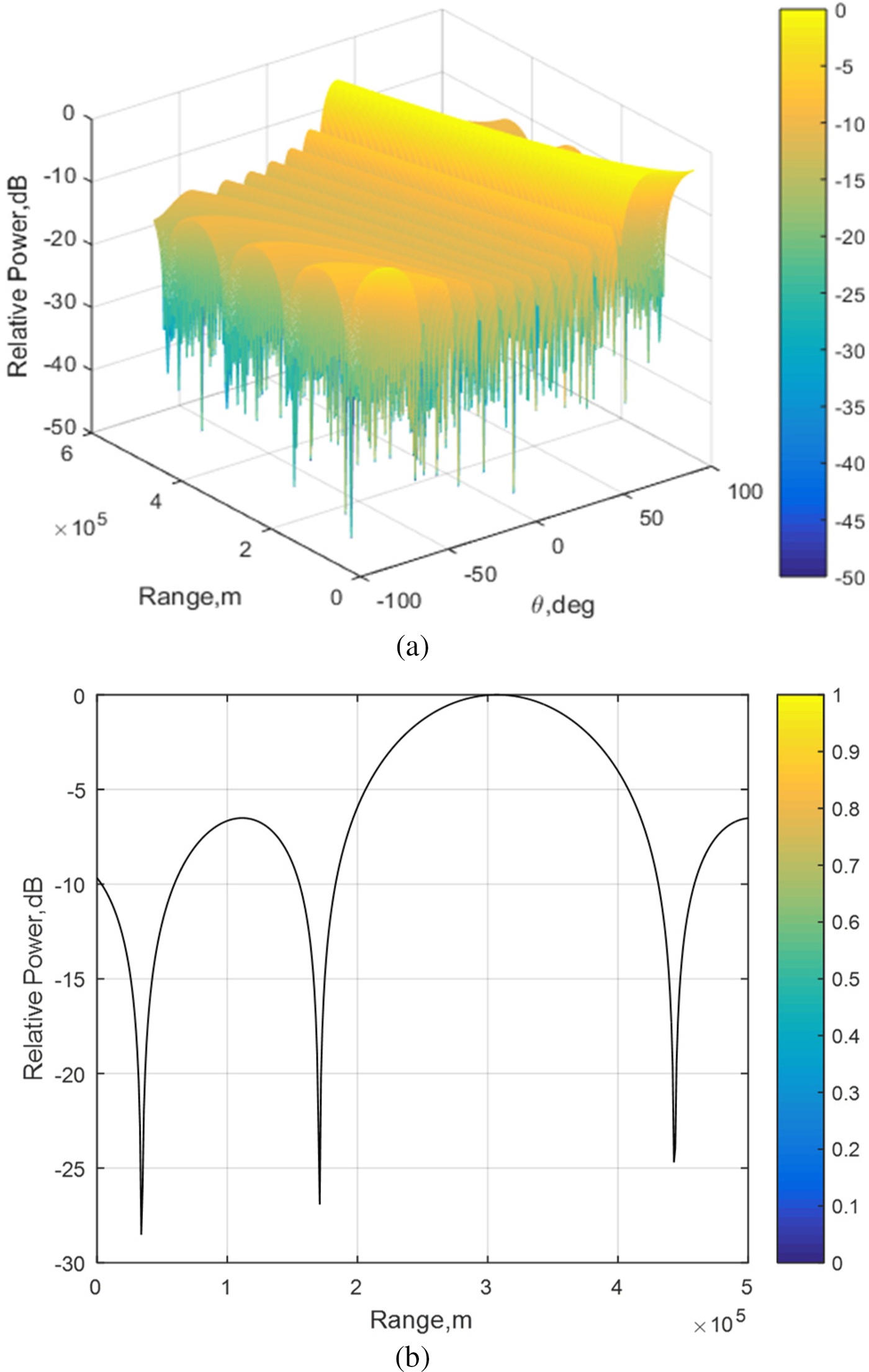
The performance of the first beampatterns for radar transmission during the active mode is bounded by (0 ≤ t ≤ t b) interval, whereas the second beampattern bearing communication during the radar listening mode is bounded by (t b <t ≤ T r) interval. As both systems are running in different time modes, the radar beam will not be affected by the second beam bearing information and will operate as the conventional FDA radar as shown in Figs 5(a) and 5(b). By doing so, the performance of DOA estimation is improved.
Example 3. Communication performance within radar listening mode:
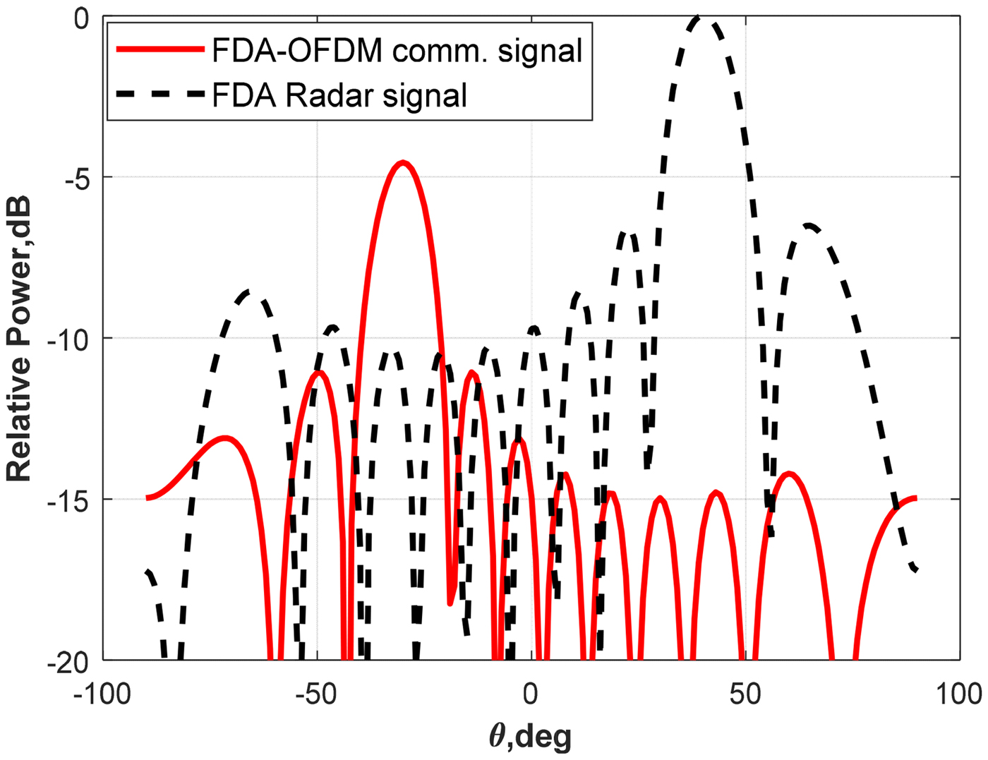
A part from example (1), we analyze here the performance of the second beampattern during the radar listening mode. Figure (6) shows two mainlobes having distinct functions. The mainlobe with a black dashed line represents the radar beampattern with spatial sector [−90 90] and power maximization toward the target at θ radar = 40°. Whereas the mainlobe with a red line represents the information embedded in the second beampattern as a communication signal with power maximization toward a communication receiver located at θ com = −30°. The maximum peak power transmitted from the array is 0 dB for radar beam, while the second beam which carries communication is less than radar in term of power by −5 dB. It is worth mentioning that there is no interference between radar and communication signal as shown in Fig. 6, because they are running in different time interval modes. The communication signal is secured at a physical layer level due to the angle fixation toward a specific receiver by directing the energy radiation toward a specific direction. This will enhance the LPI property against any eavesdropper located outside the boreside transmission.
Example 4. Data rate analysis:
Here we evaluate the communication performance operation during radar listening mode, to recover the information data transmitted during this mode, we re-call equation (21) as
 $$s_2\lpar t \rpar = \mathop \sum \limits_{m = 1}^M b_m^H \; e^{\,j2\pi \,f_mt}\; e^{-j\Phi _m}.$$
(a) FDA transmit beampattern. (b) Slant range versus relative power of FDA.

FDA and FDA-OFDM transmitted beampatterns versus spatial angle toward a specific angle for LPI property.

For the purpose of checking the orthogonal property of the above equation, we may re-write it as
 $$\eqalign{s_2\lpar t \rpar = &\mathop \sum \limits_{m = 1}^M {\bf b}_m^H \,e^{-j\Phi _m}\; e^{(\,j2\pi \; f_mRm)/c} \cr & \times \int\limits_{\varepsilon /\Delta f}^{(\varepsilon + i)/\Delta f} {e^{\,j2\pi \lpar {m-1} \rpar \Delta ft}\,e^{\,j2\pi \lpar {n-1} \rpar \Delta ft}} \,dt,} $$
where ε represents a positive real number and n & m represents different frequencies to show the orthogonality among them, where n ≠ m in case of zero and n = m in case of one. Taking the Fourier transform after multiplying the above equation by the rectangular function we get
 $$z\lpar t \rpar = \mathop \smallint \limits_{-\Delta T/2}^{\Delta T/2} s_2\lpar t \rpar \,{\rm rect}\left( {\displaystyle{t \over {\Delta T}}} \right)\,e^{\,j2\pi \; f_mt}\,dt.$$
The corresponding result after the analysis is
 $$z\lpar t \rpar = \mathop \sum \limits_{m = 1}^M b_m^H \,e^{-j\Phi _m}.\Delta T.\sin c\lpar {\,f + \; f_m} \rpar \Delta T.$$
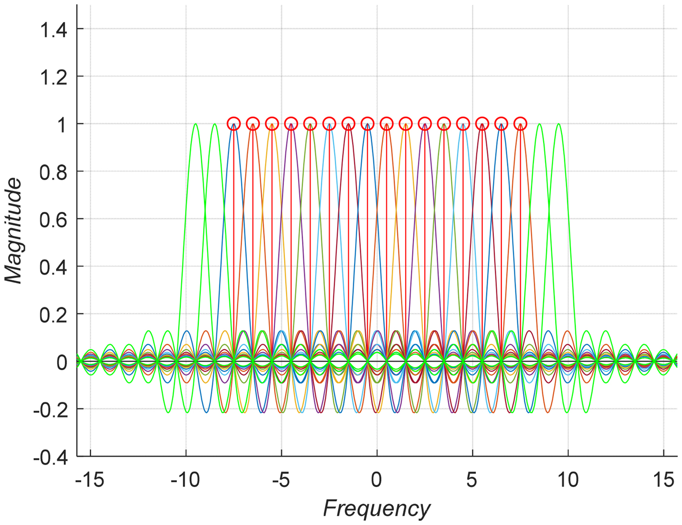
The above equation shows that, each carrier frequency is orthogonal with each other in the frequency domain for the second beam during radar listening mode and confined within a limited range time ΔT as shown in Fig. 7.
Frequency spectrum of each carrier shows the confined symbol duration within a range timing.

The BER for this system may be given as
 $${\rm BER} = Q(\sqrt {2.E_s/N_o)} \;, $$
where E s/N o is the signal-to-noise ratio and Q(.) is the complementary Gaussian error function.
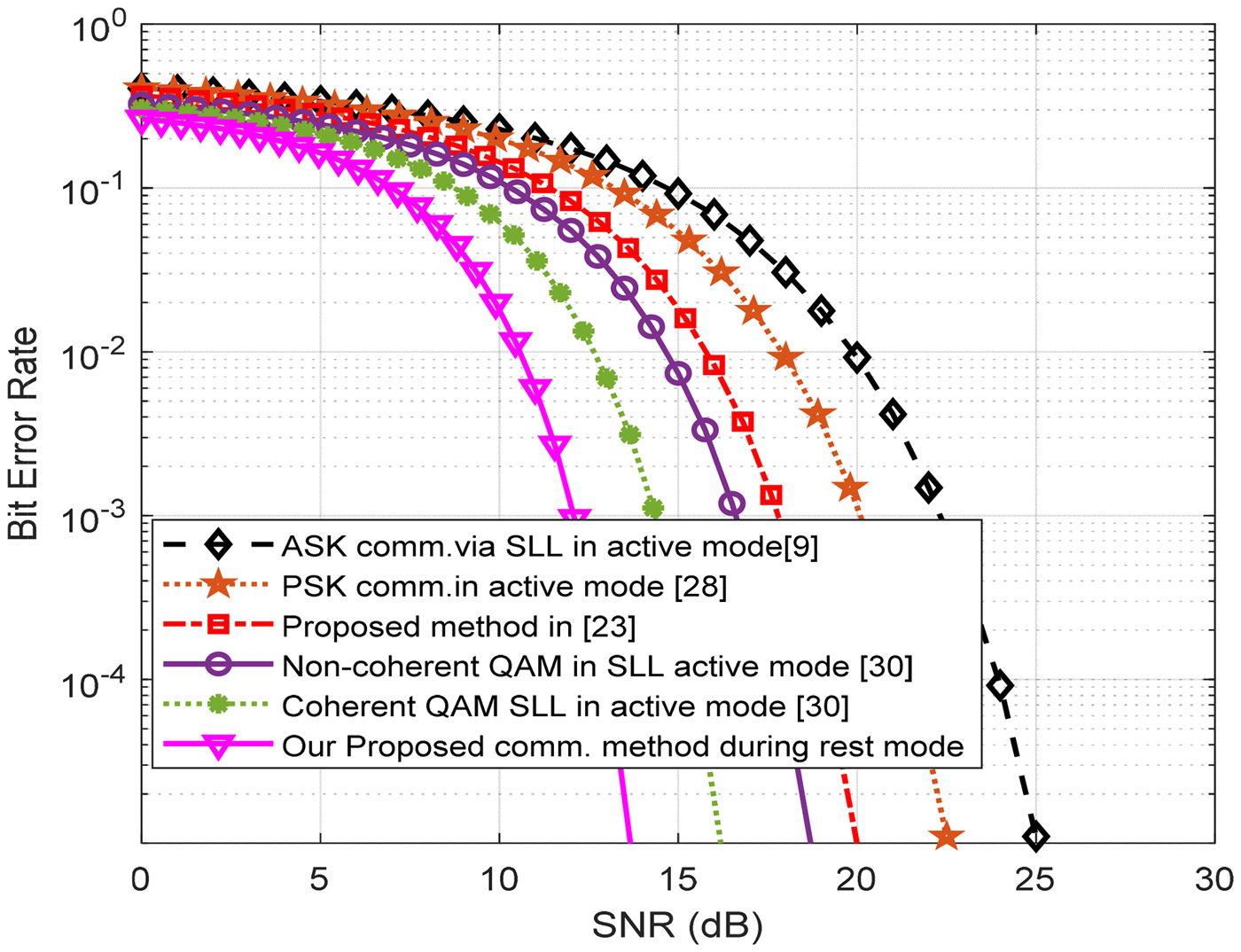
Hence, the achievable data rate can be calculated as the number in bits per symbol transmitted during radar listening mode time. Where the radar pulses T p are associated with their corresponding time intervals T s available for listening mode. So the achievable data rate in bits per second can be defined as the number in bits per symbol B times the number of symbol Q times the duration intervals T s available for uplink transmission times. In Fig. 8, the communication transmission occurred in the mainlobe of the second beampattern leads to improve the BER as compared to the sidelobe design of the previously existing systems [Reference Hassanien, Amin, Zhang and Ahmad9, Reference Ji, Chen, Hu, Pan and Shao22, Reference Nusenu, Huaizong, Ye, Xuehan and Basit23, Reference Ahmed, Zhang and Gu25]. To test BER, a sequence of 105 symbols is transmitted. It is evident that our proposed system have better achievement and shows some improvement of overall throughput or sum data rate because the transmission occurred in the mainlobe of communication for a longer time rather than that which used in active mode. In our proposed scheme, the communication transmission has gone through the high gain transmission of the second beampattern. The BER is improved when high gain lobe is transmitted toward a communication receiver. This also proved the superiority of the proposed system among existing techniques. It is very vivid from the figure above that the utilization of high gain mainlobe for communication in the absence of radar target yields a better BER as compared with the sidelobe-based communication.
Example 5. SINR versus SNR parformance Analysis for the joint FDA platform:
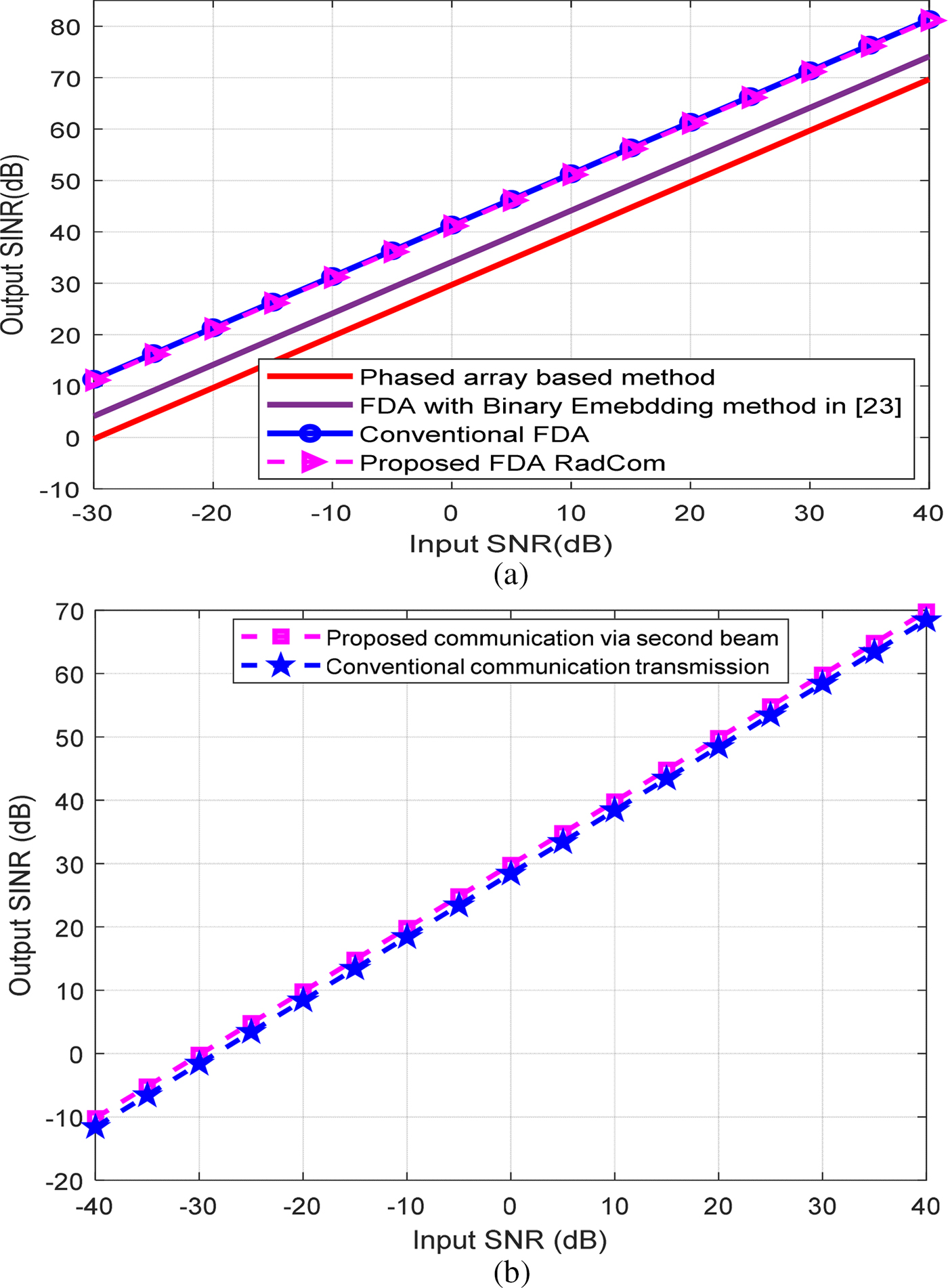
In this example, the performance analysis of our proposed RadCom system in terms of SINR is shown and compared with the performance FDA conventional, phased array system and FDA RadCom proposed in [Reference Ji, Chen, Hu, Pan and Shao22]. The SINR for these systems has been plotted against SNR as shown in Fig. 9(a). For radar evaluation, we consider an interference located at (−30°, 9 km). Hence the proposed scheme has the ability to suppress the interference in both angle and range dimensions; the expected results are better than that of the phased array techniques. Moreover our system does not alter the radar waveform with any binary information embedding during radar active mode; this leads to the identical result of the FDA conventional. Our proposed system radiated toward the intended area and gives better SINR versus SNR as compared with [Reference Ji, Chen, Hu, Pan and Shao22]. We have achieved a slightly improved performance than conventional FDA. Similarly, for communication evaluation, we consider the second beampattern transmission with interference located at 40°. The SINR versus SNR simulation in Fig. 9(b) shows that our proposed system during radar listening mode outperforms the conventional communication transmission. Overall our proposed system has better robustness characteristics against any eavesdropping and noise occurrence.
Example 6. CRLBs:
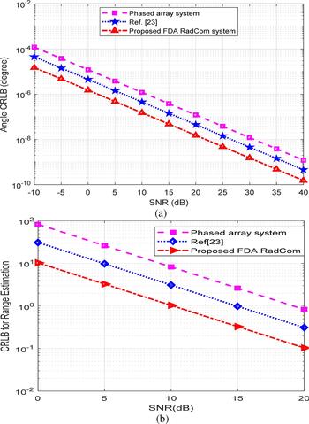
To investigate the radar performance system within the active mode, CRLBs have been plotted in both angle and range as shown in Figs 10(a) and 10(b), respectively. We comparatively simulate the following radar systems: (i) phased array system; (ii) FDA RadCom given in [Reference Ji, Chen, Hu, Pan and Shao22]; (iii) our proposed RadCom scheme. By using equation (35), we simulate the target signal of interest reflected from angle 30° and equation (36) to compute the range for the proposed system at 9 km. The CRLB for three radars is quite good; however, the proposed RadCom outperforms the phased array radar and FDA RadCom in [Reference Ji, Chen, Hu, Pan and Shao22].
BER versus SNR for joint function radar–communication.

(a) SNR versus SINR for FDA functionalities under both cases (conventional and RadCom). (b) SNR versus SINR for second beampattern bearing communication.

(a) CRLB for estimating angle versus SNR. (b) CRLB for estimating range versus SNR.

This improvement in estimation performance occurred because we did not alter or embed any communication signal during radar active mode radiation as authors did in [Reference Ji, Chen, Hu, Pan and Shao22]. They used to alter the radar functionalities during active mode, which led to keep the system ranging in the middle between conventional FDA and phased array systems. Therefore, they limited their results by upper and lower bound of angle to maintain an adequate performance. It is worth noting that increasing or decreasing the incremental frequency does not have a sever influence on CRLB, while that the CRLB can be improved if the antenna elements are increased.
Conclusion
In this paper, we have developed a novel approach for the dual function of FDA radar–communications system. We have availed the listening mode of FDA pulsed radar for the communication transmission in order to get a unified transmitter/receiver platforms. Communication transmission is achieved via radiating a communication signal during the radar listening mode. The uplink/downlink of communication takes place when the radar is in listening mode. The approach has first performed the radar functionalities during the active mode and steers the main beam toward a target. Then, the hybridization-based FDA-OFDM information-bearing communication beampattern was transmitted during the FDA listening mode toward the pre-defined receiver. At the receiver side, two matched filters are used to separate the incoming beampatterns of radar and communication from different spatial angles. Results in terms of transmit/receive beampattern for the joint system has been presented to show the feasibility of the proposed system. We have achieved good results in communication side with high capability of interference rejection and improved BER. Finally, we showed that the designed joint system does not suffer from the interference emissions of each other in their main beam directions. Simulation results have shown the effectiveness of the proposed scheme.
 Abdul Rahman Al-Salehi is a PhD scholar in Electrical Engineering from IIUI. He received his BSc. degree in Electrical Engineering from the University of Engineering and Technology (UET) Peshawar in 2007 and his Master degree in Electrical Engineering from University of Engineering and Technology (UET) Lahore in 2010. His area of interest is radar signal processing, frequency diverse array radar (FDA), optimization techniques, MIMO radar, optical communication, and an integration of radar and communication techniques.
 Ijaz Mansoor Qureshi received the B.E. degree in avionic engineering from NED University Karachi, Pakistan, the M.S. degree from Department of Electrical Engineering, METU, Ankara, Turkey, in 1980. He did his PhD from University of Toronto, Canada, in 1985. He has worked as professor at various universities in Pakistan including Quaid -e Azam University (1987–2002), Muhammad Ali Jinnah University (2002–2007), International Islamic University (IIU) (2007–2009). Since 2009, he has been working as a professor and Incharge graduate program with Department of Electrical Engineering, Air University, Islamabad, Pakistan. He is also the director of Institute of signals, systems and soft computing (ISSS), Islamabad, Pakistan. He has around 300 publications in the various fields of engineering. His research interests are digital communication, radar signal processing, image processing, soft computing and Engineering computational mathematics.
 Aqdas Naveed Malik received the Ph.D. degree from MAJU, Pakistan, in 2006. He has over 15 years post Ph.D. experience in teaching and research at different intuitions of good repute in Pakistan. More than three Ph.D.s have been produced in his supervision. He is currently the Vice President of Higher Studies & Research (HS&R) and the Dean Faculty of Engineering and Technology, International Islamic University Islamabad, Pakistan. His research interests include digital/wireless communications, digital signal processing, information, and power electronics.
 Wasim Khan received his B.S. degree in computer engineering from COMSATS University, Abbottabad, Pakistan, in 2005. And he received his M.S. and PhD degrees in Electrical Engineering from International Islamic university, Islamabad (IIUI), Pakistan, in 2008 and 2016 respectively. Since 2009, he has been working as a Lecturer in Department of Electronic Engineering at IIUI, Pakistan. His research interests are Radar signal processing, MIMO radar, frequency diverse array (FDA) radar and Hybrid of MIMO radar with phased array and FDA radar.
 Abdul Basit received his B.S. degree in Electronic Engineering from Muhammad Ali Jinnah University Islamabad in 2007 and M.S. and PhD degrees in Electrical Engineering from International Islamic university, Islamabad (IIUI), Pakistan, in 2009 and 2016 respectively. He is currently a Lecturer in Department of Electronic Engineering at IIUI, Pakistan. His main areas of research are Radar signal processing, cognitive radar, frequency diverse array radar (FDA) and Hybrid of cognitive radar with phased array and FDA radar.