1. Introduction
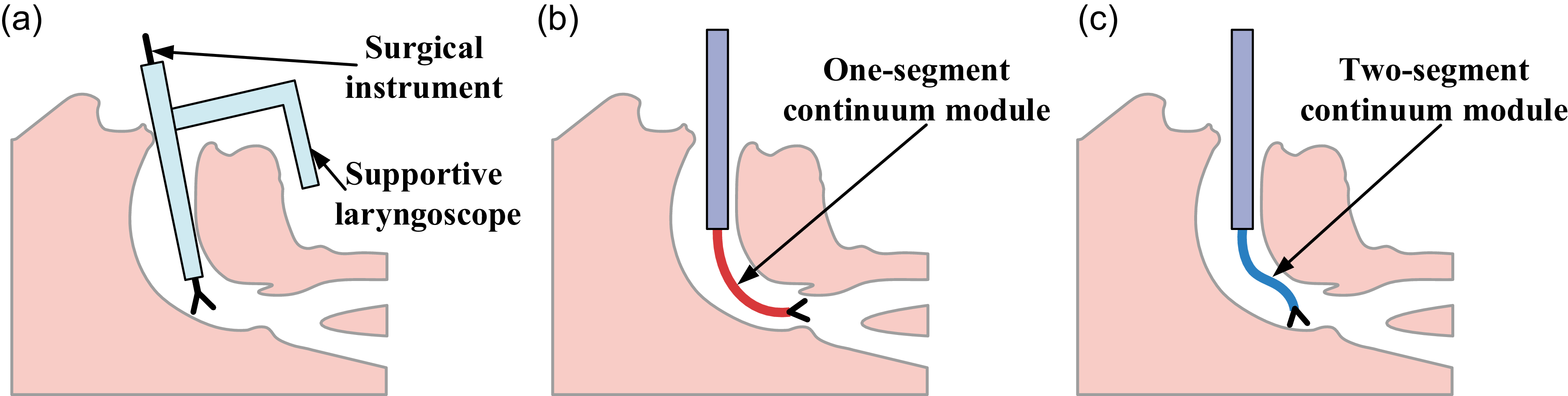
The larynx is a vital organ responsible for multiple functions, including breathing and vocalization. [Reference Dziegielewski, Kang and Ozer1]. The lesions of the larynx may cause narrowing of the laryngeal cavity, affecting breathing and, in severe cases, endangering life. To treat laryngeal diseases, especially laryngeal cancer, doctors perform open or minimally invasive surgery [Reference Poon, Li, Gao, Ren and Lim10, Reference Xu, Zhao and Zheng36]. In open surgery, an external incision is made to access and treat the affected laryngeal tissue. This surgical approach is less commonly adopted due to its higher risk of infection, prolonged recovery, and frequent complications [Reference Obid, Redlich and Tomeh15]. In minimally invasive surgery, a supportive laryngoscope establishes a surgical channel within the patient’s cavity. Doctors hold rigid surgical instruments and perform treatment through the channel [Reference Piazza, Peretti and Poorten2], as shown in Figure 1(a). This narrow surgical pathway constrains the range and precision of operation with long-handled rigid instruments. Furthermore, some lesions fail to be observed due to the limited field of view [Reference Li, Gu, Xiao, Lim and Ren11].
Different methods of laryngeal surgery. (a) Traditional laryngeal surgical method. (b) Laryngeal surgical method based on a one-segment CR. (c) Laryngeal surgical method based on a two-segment CR.

The emergence of CRs provides new ideas for solving the above problems. CRs, with compact size, spatial flexibility, and agility, can perform surgical procedures within a constrained cavity canal [Reference Mao, Yang, Tian, Shen, Wang, Zhang, Meng and Xie26, Reference Schäfer, Glöckner, Friedrich, Meiringer and Pott32, Reference Chen, Ming and Qin35]. In laryngeal surgery, the bending ability of CRs expands the surgical view and operating space. In ref. [Reference Wang, Wang, Yang, Du and Yan4], a notch continuum manipulator was developed for laryngeal surgery. In ref. [Reference Kong, Wang, Zhang, Song and Li5], a CR with in situ torsion was developed, which can maintain the position and approach vector of the end-effector during the operation. In ref. [Reference Xu, Song, Zhang, Wang and Shi6], an extensible CR with growing motion capability was developed for improved flexible access in transoral laryngeal procedures. However, these robots can only achieve overall bending, as shown in Figure 1(b). Their limited configurations lack the dexterity required to access specific lesion sites. Therefore, a CR composed of multiple segments is required.
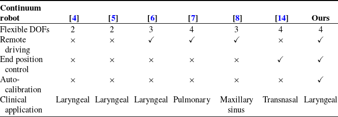
As the number of segments in a CR increases, controlling it becomes progressively more challenging [Reference Chen, Renda, Gall, Mocellin, Bernabei, Dangel, Ciuti, Cianchetti and Stefanini9]. To balance flexibility and control precision, a two-segment CR is an appropriate choice for laryngeal surgery, as shown in Figure 1(c). Although some two-segment CRs have been developed for other surgeries, the requirements differ for each type of operation. A two-segment CR was developed for maxillary sinus surgery [Reference Hong, Feng, Xie and Yang8]. The proximal segment of the CR can only bend in one direction, resulting in limited flexibility. The end-effector position of the two-segment CR in ref. [Reference Bian, Wang, Li, Zhang, Wang, Wu, Guo and Li7] is not controllable, increasing operational difficulty. The Da Vinci SP system was primarily developed for single-port laparoscopic surgery [Reference Van Abel, Yin, Price, Janus, Kasperbauer and Moore37]. However, it struggles to reach the deep laryngeal due to its large structure. The concentric wire-driven robot in ref. [Reference Kong, Zhang, Lin, Wang, Song and Li14] demonstrates good dexterity, workspace, and operational precision, making it suitable for transnasal procedures. However, its large actuation unit poses potential risks of interference with the human body when applied to transoral laryngeal surgery. Therefore, a remote actuation structure is indispensable. In summary, it is crucial to design a highly flexible, positionally controllable, and remote-actuation two-segment CR for laryngeal surgery.
The modeling approaches of CRs can be categorized into two types: model-free methods and model-based methods. Model-free methods rely on sampled data to fit the relationship between the actuation inputs and the end-effector pose. In ref. [Reference Thuruthel, Falotico, Renda and Laschi29], a nonlinear autoregressive network with exogenous inputs was used to construct the forward dynamic model, achieving long-term predictions. In ref. [Reference Wang, Wang, Yang, Du and Yan4], a machine learning model was employed to capture the inverse kinematics. The end position of the CR is used as the input, and the driving force is used as the output. During the inverse kinematics solution, a particle swarm optimization-based back propagation neural network was proposed to compensate for the errors caused by assembly tolerances and friction [Reference Bian, Wang, Li, Zhang, Wang, Wu, Guo and Li7]. In ref. [Reference Ji, Yan, Du, Yan, Chen, Lu, Rojas and Cheng34], a model-free multi-agent reinforcement learning, namely multi-agent deep Q network, is adopted to control a 2-degree-of-freedom cable-driven CR. However, collecting large amounts of real-world data may lead to issues such as mechanical wear and tendon slackening.
In contrast, model-based methods establish the motion mapping through physical and geometric analysis. Currently, the model-based methods mainly rely on the constant curvature hypothesis [Reference Peng, Wang and Lu20, Reference Du, Zhang, Zhang and Wang31, Reference Cobos-Guzman, Palmer and Axinte33] or variable curvature hypothesis [Reference Iqbal, Esfandiari, Amirkhani, Hoshyarmanesh, Lama, Tavakoli and Sutherland21, Reference Zhang, Gao and Ren22], where each segment is considered to bend with continuous or discontinuous curvatures. In the inverse kinematics, the Jacobian matrix is commonly used to map end-effector position change to actuation [Reference Wang, Fang, Wang, Xie, Lee, Ho, Tang, Lam and Kwok16]. Due to singularity when the continuum segments approach straightened states (the curvatures approach zeros), even small position changes can result in large variations in deflection angles. The phenomenon may cause the inverse kinematics to become unreliable [Reference Wang, Ye, Kang, Wang, Luo, Chen and Tang18, Reference Armanini, Boyer, Mathew, Duriez and Renda19]. To address the singularity, modal basis functions are used to represent the position components in the homogeneous transformation matrix [Reference Lai, Huang, Lu, Zhao and Chu12, Reference Godage, Guglielmino, Branson, Medrano-Cerda and Caldwell17]. Although the representation can describe the state of continuum segments when straightened, it still fails to handle disturbances caused by the large deflection angle variations over a short period. DLS, task-priority redundancy resolution, and modal approaches are common and robust inverse kinematics solution methods [Reference Lai, Huang, Lu, Zhao and Chu12, Reference Zhang, Du, Qin, Zhao and Yang30, Reference Villalobos, Sanchez and Martell38], but their performance in CR motion remains to be considered. As a result, the failure of the inverse kinematics may cause the CR to abruptly halt during motion planning, preventing it from reaching the intended target.
The effectiveness of the modeling relies on the calibration of the initial state, where the continuum segments are fully straightened. Accurate calibration ensures that the control of CRs closely follows the modeling principle [Reference Lai, Huang, Lu, Zhao and Chu12]. Due to the stringent hygiene requirements in surgical environments, the continuum components, as the parts that come into direct contact with the patient, will be frequently replaced [Reference Blanco, Ha, Califano and Saunders3]. Therefore, the calibration will often occur.
During the manual calibration, each motor corresponding to a tendon is adjusted individually and repeatedly based on expert experience. The process is tedious and complex, which may increase the surgery preparation time. At this point, an automatic calibration algorithm is desired. To quantitatively assess the state of drive tendons, force sensors are typically applied [Reference Bian, Zhang, Ye, Ren, Zhai, Ma and Li23, Reference Bian, Zhang, Ye, Ren, Zhai and Ma24]. However, the introduction of multiple sensors would complicate the CR system [Reference Deng, Wei, Pan, Li and Hu25]. Hence, it is valuable to achieve autonomous calibration without additional force sensors.
Currently, laryngeal surgery faces the limitation in operational flexibility. To address the issue, a novel two-segment CR system is proposed with a robust inverse kinematics algorithm and a sensorless automatic calibration method. The contributions of this paper are summarized as follows:
-
1. A CR system is proposed for laryngeal surgery, which provides sufficient surgical DOFs. The ample DOFs enable the CR to be controlled in both angles and end-effector position, offering operational flexibility. Phantom and animal experiment results demonstrate the flexibility, practicality, and reliability of the proposed CR system.
-
2. To address the singularity, an improved Jacobian-based inverse kinematics algorithm is proposed. The algorithm effectively mitigates potential disturbances caused by curvature hypotheses, ensuring continuity of motion planning near the singular point.
-
3. An automatic calibration algorithm is proposed for CRs. The algorithm enables efficient and automatic calibration of the initial state without additional sensors, which reduces human intervention and shortens the preparation time for laryngeal surgery.
2. Continuum robot system design
According to clinical studies on laryngeal surgery [Reference Sampieri, Costantino, Pirola, Kim, Lee and Kim13, Reference Ushiro, Watanabe, Kishimoto, Kawai, Fujimura, Asato, Tsujimura, Hori, Kumabe, Yasuda, Tamaki, Iki, Kitani, Kurata, Kojima, Takata, Kada, Takebayashi, Shinohara, Hamaguchi, Miyazaki, Ikenaga, Maetani, Harada, Haji and Omori27, Reference Kuroki, Shibata, Kobayashi, Matsubara, Akita, Yamada, Kato, Iinuma, Kawaura, Okuda, Mori, Ueda, Miyazaki and Ogawa28], the laryngeal cavity is narrow and curved, with a diameter of approximately 25 mm. Therefore, the CR’s manipulation arm must be compact. Functionally, the manipulation arm should be capable of overall bending and insertion, while maintaining dexterous movement under curved conditions. Moreover, the end of the CR should accommodate surgical instruments, such as grippers and endoscopes. Based on these requirements, the CR system is designed to include a continuum module, a linkage, an actuation module, a linear slide, and a collaborative robot, as shown in Figure 2.
Continuum robot system for laryngeal surgery, mainly including a continuum module, a linkage, an actuation module, a linear slide, and a collaborative robot.

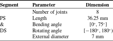
The core component of the CR is the continuum module. To enhance operational flexibility, the continuum module is composed of two segments: the proximal segment (PS) and the distal segment (DS). Each segment is driven by 3 tendons distributed at
 $120^\circ$
intervals. Adjacent tendons from different segments are separated by
 $60^\circ$
. The drive tendons are fixed at the ends of their respective segments. Based on this drive pattern, each segment has 2 DOFs independently, enabling bending and rotation. At the same time, PS and DS can also be viewed as a single continuum segment, enabling overall bending and rotation. The specific parameters of the segments are shown in Table I. The central lumen is used as a functional channel. The functional lines of the surgical instruments can pass through this channel, such as drive lines for grippers and signal lines for endoscopes. The continuum module, combined with the instruments, constitutes the manipulation arm.
Segment parameters of continuum module.

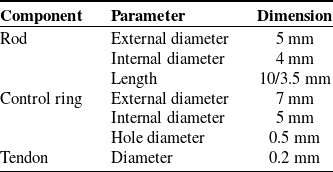
Component parameters of continuum module.

The basic components of the continuum module include rods, control rings, and tendons. To ensure the continuum module can bend in all directions, adjacent rods are connected by orthogonal joints. The opening between adjacent rods is designed to be 1 mm. In this condition, each joint has sufficient bending curvature. The control rings are welded onto each rod to ensure the tendons are securely aligned along the module, thereby guaranteeing effective control over the module. Among all the control rings, there are three special types: the base control ring, the PS control ring, and the DS control ring. The base control ring is closest to the linkage. The PS and DS control rings are used to fix the PS tendons and DS tendons, respectively. The specific parameters of the components are shown in Table II.
To facilitate entry into the oral cavity and larynx, a remote driving structure is designed. The slender linkage connects the manipulation arm to the actuation module. To prevent the tendons from tangling, a support frame is installed inside the linkage. The support frame consists of tubes and supports. Each tendon corresponds to a tube and passes through it. The support frame maintains the position and phase relationship of the tubes. The actuation module primarily drives the manipulation arm, with motor rotation translated into tendon tension via pulleys. The linear slide is designed to facilitate insertion into and withdrawal from the cavity. The collaborative robot is used to adjust the overall pose of the CR. Different modules are secured together using connectors.
Based on the aforementioned designs, the manipulation arm can easily access the cavities and achieve dexterous end-effector movement following the intervention. Equipped with different surgical instruments, the CR system is capable of performing a variety of surgical tasks.
3. Kinematic modeling
In this section, we present the kinematic models of the CR, including the overall and segmented models. In the overall model, PS and DS are modeled as a single segment, achieving overall bending and rotation. The overall motion is crucial during cavity intervention. In the segmented model, the motion of PS and DS is, respectively, modeled, enabling end-effector position control. This feature contributes to the dexterous movement of the surgical tools.
3.1. Overall model
The overall model is an improvement based on the constant curvature hypothesis. As illustrated in Figure 3, the overall segment consists of
 $n$
joints. Since adjacent joints are orthogonal, every two joints are considered as a unit. Hence, there are a total of
 $n/2$
units. All the units are in the same bending plane
 $\alpha$
. The angle corresponding to bending unit
 $i$
is
 $\beta _i$
. The relationship among
 $\beta _1$
,
 $\beta _2$
,…, and
 $\beta _{n/2}$
is:
 \begin{equation} \beta _1=\beta _2=\cdots =\beta _{n/2} \end{equation}
Therefore, the overall segment is considered a circular arc with uniform curvature. The bending angle of the overall segment is
 $\beta$
:
 \begin{equation} \beta =\overset {n/2}{\underset {i=1}{\sum \beta _i}}=\frac n2 \beta _1 \end{equation}
Kinematic model of the continuum module. (a) Overall model with bending parameters
 $\beta$
(bending angle) and
 $\alpha$
(deflection angle). (b) Segmented model with bending parameters
 $\beta _i$
(bending angle) and
 $\alpha _i$
(deflection angle) in the segment
 $i$
.

The relationship between tendon displacement
 $\Delta l=\left \{\Delta l_{kj}\vert k=1,2;\;j=1,2,3\right \}$
and angle parameters
 $\Theta =\left \{\alpha ,\;\beta \right \}$
is as follows:
 \begin{equation} \triangle l_{kj}={-}\left(\frac {L_1}{L} \right)^{2-k}\beta d (c\alpha _{kj}) \end{equation}
 \begin{align} \alpha _{kj}=\left \{\begin{array}{l} \left(\dfrac 23j-\dfrac 13 \right)\pi -\alpha ,\;k=1\\[12pt] \left(\dfrac 23-\dfrac 23j \right)\mathrm \pi +\alpha ,\;k=2\end{array}\right . \end{align}
where
 $d$
is the distance between the tendon center axis and the overall segment center axis.
 $L_1$
and
 $L$
denote the lengths of the overall segment and PS centerlines, respectively.
The coordinate systems are defined on the end face of the control rings. The center of each control ring’s end face is taken as the origin. The
 $Z$
axis of each coordinate system is perpendicular to the end face of the control ring, pointing upwards. The
 $X$
axis passes through the centerline of the DS tendon
 $l_{21}$
, pointing outwards.
The transformation matrix
 $T_i$
between
 $X_{i-1}-Y_{i-1}-Z_{i-1}$
and
 $X_{i}-Y_{i}-Z_{i}$
is as follows:
 \begin{equation} T_i=e^{\left [S_i\right ]\beta _i},\quad \left [S_i\right ]= \left[\begin{array}{c@{\quad}l}\left [w_i\right ]&v_i\\0_{1\times 3}&0\end{array}\right],\quad v_i=-w_i\times c_i \end{equation}
where
 $w_i$
is the axis of rotation,
 $\left [S_i\right ]$
is the skew-symmetric matrix of the rotation axis, and
 $c_i$
is the center of rotation. The calculations yield
 $w_i=\lbrack -s\alpha ,\;c\alpha ,\;0\rbrack ^T$
and
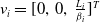 $v_i=\lbrack 0,\;0,\;\frac {L_i}{\beta _i}\rbrack ^T$
, where
 $c$
is the abbreviation for
 $cos$
,
 $s$
is the abbreviation for
 $sin$
, and
 $L_i$
is the length of the centerline between
 $X_{i-1}-Y_{i-1}-Z_{i-1}$
and
 $X_{i}-Y_{i}-Z_{i}$
. Based on the above assumptions, the following conclusions can be drawn:
 \begin{equation} w_1=\cdots =w_{n/2},\quad v_1=\cdots =v_{n/2},\quad \left [S_1\right ]=\cdots =\left [S_{n/2}\right ] \end{equation}
The forward kinematics
 $T_O$
of the overall segment can be obtained by the exponential product method:
 \begin{equation} T_O=\prod _{i=1}^{n/2}e^{[S_i] \beta _i} T_0=e^{[S_1]\beta } T_0,\quad T_0 = \left[\begin{array}{l@{\quad}l}I_{3\times 3}& [\begin{array}{l@{\quad}l@{\quad}l} 0 & 0 & L]\end{array} ^T\\0_{1\times 3}&1\end{array}\right] \end{equation}
Convert
 $T_O$
into a homogeneous transformation matrix:
 \begin{equation} T_O = \left[\begin{array}{l@{\quad}l}R&b\\[3pt] 0&1\end{array}\right],\quad b=\begin{bmatrix}-L c\alpha (c\beta -1)/\beta \\[4pt] -L s\alpha (c\beta -1)/\beta \\[5pt] L s\beta /\beta \end{bmatrix} \end{equation}
In the initial state,
 $\beta$
approaches
 $0$
, which leads to the numerical singularity in
 $b$
. Specifically, each term in
 $b$
exhibits a
 $0/0$
form. In floating-point computations, when both the numerator and denominator are close to zero, catastrophic cancellation can occur, leading to substantial numerical errors. To avoid the issue,
 $b$
is expanded by a sixth-order Taylor series:
 \begin{equation} b = \left[\begin{array}{l}L (c\alpha ) \beta \left(\dfrac 12-\dfrac {\beta ^2}{24}+\dfrac {\beta ^4}{720} \right)\\[12pt] L (s\alpha ) \beta \left(\dfrac 12-\dfrac {\beta ^2}{24}+\dfrac {\beta ^4}{720}\right)\\[12pt] L \left(1-\dfrac {\beta ^2}6+\dfrac {\beta ^4}{120}-\dfrac {\beta ^6}{5040}\right)\end{array}\right] \end{equation}
Assume
 $\beta$
is 3°, the relative computational error caused by Eq. (9) is less than
 $10^{-12}$
. Moreover, Eq. (9) replaces the original sine and cosine evaluations with approximately ten multiplications and additions, significantly improving computational efficiency. Therefore, this treatment avoids catastrophic cancellation while maintaining both numerical computational and efficiency.
From the above description,
 $\alpha$
and
 $\beta$
are used as control parameters to manage the bending direction and degree of the overall segment.
3.2. Segmented model
The segmented model follows the previous assumption. The relationship between
 $\Delta l$
and
 $\Theta =\left \{\alpha _k,\;\beta _k\vert k=1,2\right \}$
is as follows:
 \begin{align} \Delta l_{kj}=-\sum _{t=1}^k\beta _t d \! \left(c\alpha _{kj}^t \right) \\[-28pt] \nonumber \end{align}
 \begin{align} \alpha _{kj}^t=\left \{\begin{array}{l}\dfrac{2}{3}(1-j)\mathrm \pi +\alpha _{t},\;t=k\\[12pt] \left(\dfrac{2}{3}j-1 \right)\pi -\alpha _t,\;t\lt k\end{array}\right . \\[6pt] \nonumber \end{align}
The transformation matrix
 $T_1$
between
 $X_0-Y_0-Z_0$
and
 $X_P-Y_P-Z_P$
is as follows:
 \begin{equation} T_1=T_{11} T_{12},\;T_{12}= \left|\begin{array}{c@{\quad}c}Rot\!\left(z,\;-\dfrac{\pi}{3} \right)&0_{3\times 1}\\[5pt] 0_{1\times 3}&1\end{array}\right| \end{equation}
where
 $T_{11}$
follows the method of Eq. (8), and
 $T_{12}$
adjusts
 $X_P$
to pass through the centerline of
 $l_{21}$
. The transformation matrix
 $T_2$
between
 $X_P-Y_P-Z_P$
and
 $X_D-Y_D-Z_D$
also follows Eq. (8).
The segmented forward kinematics is:
 \begin{equation} T=T_1 T_2=f(\Theta ) \end{equation}
Since the linear slide can move along the
 $Z_0$
direction, only movements in the
 $X_0$
and
 $Y_0$
directions require to be considered in the segmented inverse kinematics, which are represented by
 $b^{xy}$
.
 \begin{equation} b^{xy}=f_b(\Theta ) \end{equation}
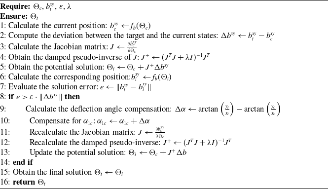
To overcome the singularity near the initial state, a novel inverse kinematics algorithm is proposed, as shown in Algorithm 1. In this algorithm,
 $\Theta _c$
is the current angle vector,
 $b_t^{xy}$
is the target end-effector position,
 $\varepsilon$
is the allowable error coefficient, and
 $\lambda$
is the damping factor. To obtain the target angle vector
 $\Theta _t$
, the Jacobian matrix
 $J$
of the current state is first computed. Referring to Eq. (15), the initial solution
 $\Theta _i$
is derived by substituting small displacement changes
 $\Delta b^{xy}$
for
 $\overset \cdot {b^{xy}}$
.
 \begin{equation} \overset \cdot {\Theta }=J^+\overset \cdot {b^{xy}} \end{equation}
where
 $J^+$
represents the damped pseudo-inverse.
 $\lambda I$
is the damping term. Then, determine whether the error
 $e$
corresponding to
 $\Theta _i$
satisfies the solving condition. If the condition is not met, it is concluded that the solution has failed due to large potential changes in
 $\alpha _{1}$
or
 $\alpha _2$
. Moreover,
 $\beta _1$
and
 $\beta _2$
approach zeros. The conclusion relies on three preconditions:
Inverse Kinematics Algorithm

Precondition 1:
 $b^{xy}$
is continuous.
Precondition 2: In the inverse kinematics based on the Jacobian matrix,
 $\Theta _t$
is required to be close to
 $\Theta _c$
.
Precondition 3: When
 $\beta _1$
and
 $\beta _2$
approach zeros, the displacement induced by significant changes in
 $\alpha _1$
or
 $\alpha _2$
is small.
As shown in Figure 4 (a), the workspace of the CR is simulated in the
 $X_0$
-
 $Y_0$
plane using the Monte Carlo method. It is observed that the workspace is continuous, thereby satisfying Precondition 1. Precondition 1 ensures the existence of the solution. In the inverse kinematics solution based on the Jacobian matrix, changes in
 $b^{xy}$
and
 $\Theta$
are small, as they are used to substitute for
 $\overset \cdot {b^{xy}}$
and
 $\overset \cdot {\Theta }$
in Eq. (15). Consequently, Precondition 2 holds. It can be inferred from Eq. (9) that when
 $\beta _{k=1,2}$
approaches zero:
 \begin{align} \underset {\beta _k\rightarrow 0}{\lim }b_{k}^x=\underset {\beta _k\rightarrow 0}{\lim }L (c\alpha _k) \beta _k \!\left(\frac 12-\frac {\beta _k^2}{24}+\frac {\beta _k^4}{720}\right)=0 \\[-29pt] \nonumber \end{align}
 \begin{align} \underset {\beta _k\rightarrow 0}{\lim }b_{k}^y=\underset {\beta _k\rightarrow 0}{\lim }L (s\alpha _k) \beta _k \!\left(\frac 12-\frac {\beta _k^2}{24}+\frac {\beta _k^4}{720} \right)=0 \\[6pt] \nonumber \end{align}
At this point, regardless of how
 $\alpha _k$
varies, both
 $b_{k}^x$
and
 $b_{k}^y$
consistently approach zeros. Expanding Eq. (14) yields:
 \begin{equation} \underset {\beta _1,\beta _2\rightarrow 0}{\lim }b^{xy}=\underset {\beta _1,\beta _2\rightarrow 0}{\lim }{R_1b_2+b_1}=0 \end{equation}
Thus, Precondition 3 is satisfied. When
 $e\gt \varepsilon ||\Delta b^{xy}||$
, it can be inferred that a small
 $\Delta b^{xy}$
corresponds to a large
 $\Delta \Theta$
.
 $\beta _1$
and
 $\beta _2$
are positively correlated with
 $b^{xy}$
. When
 $\beta _1$
or
 $\beta _2$
are nonzeros, changes in
 $\alpha _1$
or
 $\alpha _2$
are similarly reflected in
 $b^{xy}$
. Therefore, the solution is limited to the single scenario where
 $\beta _1$
and
 $\beta _2$
approach zeros, and
 $\alpha _1$
or
 $\alpha _2$
undergo substantial changes.
Supplementary explanation of the inverse kinematics. (a) Workspace simulation in the
 $X_0$
-
 $Y_0$
plane. (b) Explanation of the compensation for
 $\alpha _{1c}$
.

To address the issue, compensation
 $ \Delta \alpha$
is applied to
 $\alpha _{1c}$
, as illustrated in Figure 4 (b).
 $\alpha _{1c}$
is chosen because, after the compensation,
 $b_c^{xy}$
and
 $b_t^{xy}$
lie on the same line extending from the zero-crossing point. Since DS is stacked on top of PS, compensating
 $\alpha _{2c}$
would be affected by PS, making it difficult to estimate. Given that both
 $\beta _{1c}$
and
 $\beta _{2c}$
approach zeros,
 $b_c^{xy}$
remains largely unchanged before and after the compensation. The compensated
 $\Theta _c$
is then inputted to Eq. (15) to obtain the final solution
 $\Theta _t$
.
The proposed inverse kinematics algorithm effectively addresses the singularity, ensuring continuity in motion planning. Based on the segmented model, the end-effector position can be used as the control parameter to approach potential targets. The proposed models allow both the angle-based and end-effector position-based control of the CR, ensuring operational convenience.
4. Automatic calibration
To reduce human intervention, an automatic calibration algorithm is proposed. The straightened state serves as the zero-reference point of the kinematic model. As force sensors are inconvenient to install on the CR system, how to measure the tension on the tendons should be considered. Instantaneous current
 $I_I$
of the drive motors can be used to evaluate the tendon tension indirectly.
 \begin{equation} G_{I}=F_{I} r=h_t I_{I} \end{equation}
where
 $G_I$
is instantaneous torque,
 $F_I$
is instantaneous tension,
 $r$
is the length of the lever arm, and
 $h_t$
represents torque constant. Since
 $r$
can also be regarded as a constant, the relationship between
 $F_I$
and
 $I_I$
is approximately linear:
 \begin{equation} F_{I}=h_t I_{I}/r \end{equation}
However, influenced by nonlinear factors such as dynamic effects, the instantaneous current tends to fluctuate significantly. As a result, the relationship between the effective tension
 $F$
and the current
 $I$
can only be considered positively correlated rather than strictly proportional:
 \begin{equation} F \propto I \end{equation}
To address the issue, distribution parameters of the current data
 $m$
and
 $s$
are used as indicators, where
 $m$
represents the mean value, and
 $s$
represents the standard deviation.
When tendon
 $j$
is properly pre-tensioned, the current distribution range
 $r_{Pj}$
corresponding to motor
 $j$
is calculated:
 \begin{equation} r_{Pj}=\lbrack m_{Pj}-2s_{Pj},\;m_{Pj}+2s_{Pj}\rbrack \end{equation}
 $R_{P}=\lbrack r_{P1},\;r_{P2},\ldots ,\;r_{P6}\rbrack$
is the standard applied to determine whether the tendons meet the condition.
Based on
 $R_P$
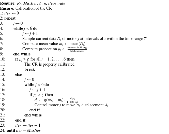
, the automatic calibration algorithm is shown in Algorithm 2.
 $MaxIter$
is the maximum iterations,
 $\zeta$
represents the proportion threshold,
 $\eta$
represents the current-displacement proportionality constant,
 $step_0$
is the initial motor step size, and
 $rate$
is the step update rate.
CR Automatic Calibration Algorithm

To assess the state of the CR, the current data are first collected and analyzed. If the following condition is met, the distribution of
 $D_j$
is considered to coincide closely with
 $r_{Pj}$
.
 \begin{equation} p_j \geq \zeta \end{equation}
In this case, the tendon corresponding to motor
 $j$
is considered to be well pre-tensioned. The CR is calibrated well only when all the tendons are simultaneously and properly pre-tensioned.
If
 $p_j$
does not meet the condition, motor
 $j$
will rotate by a displacement
 $d_j$
:
 \begin{equation} d_j=\eta (m_{Pj}-m_j) \frac {step_0}{1+rate\times iter} \end{equation}
The direction of the rotation is determined by
 $\operatorname {sgn}(m_{Pj}-m_j)$
. When the tendon is slack (
 $m_j\lt m_{Pj}$
), motor
 $j$
rotates in the forward direction; when the tendon is over-tensioned (
 $m_j\gt m_{Pj}$
), motor
 $j$
rotates in the reverse direction. Therefore, the algorithm can handle both slack and over-tensioned situations. Since
 $|m_{Pj}-m_j|$
represents the deviation of tendon
 $j$
from the current state to the pre-tensioned state,
 $|d_j|$
is designed to maintain a proportional relationship with it. Moreover, considering that the CR gradually approaches the calibrated state as the number of iterations increases, a decay mechanism
 $\frac {1}{1+rate\times iter}$
is introduced. The algorithm proceeds iteratively until all
 $p_{j=1,\ldots ,6}$
satisfy Eq. (24). Once the condition is met, the CR is considered successfully calibrated.
5. Experiments and analysis
5.1. Experimental setup
To evaluate the performance of the proposed CR system, simulation experiments and an animal experiment are conducted. Accordingly, two experimental setups are designed, as illustrated in Figure 5.
Experimental setup. (a) Simulation experiment setup. (b) Animal experiment setup.

5.1.1. Simulation experiment setup
The simulation experiments include an automatic calibration test, an inverse kinematics algorithm test, a trajectory tracking test, a tube intervention test, and a phantom test. These experiments are conducted to analyze and discuss the calibration and motion capabilities of the CR system.
In the CR system, grippers and an endoscope are used as the instruments. The maximum allowed values of the bending angle parameters
 $\beta _1$
and
 $\beta _2$
are preset (
 $75^\circ$
). When
 $\beta _1$
and
 $\beta _2$
reach their respective limits during motion, the CR halts and triggers an alert. This approach helps to prevent DS hyperextension. The tendons used in the experiments are made of NiTi alloy, which possesses sufficient strength to prevent failure and exhibits almost no deformations after autoclaving [Reference Shahawi and Aboalnaga39, Reference Sastri40]. Protescap 16ECP36 motors are used in the actuation module, and the specification of the gearbox is R16 (121:1). The driver model is Elmo Gold Twitter. An industrial computer with an Intel i7 processor is used as the controller.
A binocular positioning device (RuiTong Max, Ariemedi, Inc., China) and reflective marker balls are utilized for capturing the end-effector position of the CR. During the measurement, the markers are fixed on the end-effector, and the positioning device infers the end-effector position by capturing the location of the markers.
5.1.2. Animal experiment setup
The animal experiment is conducted to validate the performance of the CR system in a real surgical scene. The experimental subject is a pig, which is anesthetized prior to the experiment. A mouth opener is used to create an access pathway. In the CR system, a gripper is mounted at the end of the manipulation arm. The electromechanical and control systems adopt the design from the simulation experiments. The CR is fixed at the end of a collaborative robot. The model of the collaborative robot is ROKAE CR7. An endoscope system is used to observe the status of the manipulation arm and the experimental scenario. The endoscope view is displayed on a monitor. Contact between the CR and tissue is monitored via endoscopic observation, using tissue deformation as an indicator of contact force.
5.2. Automatic calibration test
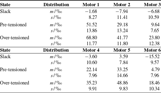
The first step is to verify the effectiveness of the instantaneous current as an evaluation indicator. The current of the motors is collected in the slack, the pre-tensioned, and the over-tensioned state. The current is sampled every 1 ms, for a total of 500 times. As shown in Table III, the current exhibits a clear difference among different states (
 $m$
represents the mean value, and
 $s$
represents the standard deviation. The values in the table represent the ratios of the motor currents to the peak value, multiplied by 1000. The positive and negative signs indicate the direction of motor rotation). It proves the effectiveness of the current in evaluating the calibration effect.
Current distributions of different states.

To construct
 $R_P$
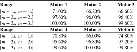
, the distribution of the pre-tensioned current data requires to be analyzed. Proportions of the data within different standard deviation ranges are shown in Table IV. These proportions are close to the ones of the normal distribution, which are
 $68.27\%$
,
 $95.45\%$
, and
 $99.73\%$
, respectively. Hence, the current data are approximately regarded as following the normal distribution. Let
 $R_P=\lbrack m-2s, \;m+2s\rbrack$
and
 $\zeta =0.95$
. The pre-tensioned state is considered to be reached when 95% of the current data fall within
 $R_P$
. This condition is based on the property of the normal distribution and accounts for the fluctuation of the current data.
Current distribution proportion of pre-tensioned state.

Continuum module automatic calibration sequence. (a)–(d) Transition of the continuum module from uncalibrated to calibrated state. (e)–(h) Transition of the tendons from slack to pre-tensioned states.

To validate the effectiveness of the algorithm, fifteen sets of autonomous calibration experiments are conducted. The ideal condition is that when the tendons are properly pre-tensioned, the continuum module reaches the straightened state. As shown in Figure 6, the tendons are randomly slackened to a certain extent in each experiment. Following Algorithm 2, each motor autonomously rotates until the ideal condition is achieved.
The hyperparameters utilized in the experiments are as follows:
 $MaxIter$
is 20,
 $\zeta$
is 0.95,
 $T$
is 5 s,
 $t$
is 1 ms,
 $step_0$
is 3500 counts, and
 $rate$
is 0.05. The end position of the continuum module is measured using the binocular positioning device. The experimental results indicate that no calibration failures are observed, and every calibration is successfully completed within 50 s. The mean absolute position error is 1.23 mm (1.70% of its length). In addition, fifteen manual calibration trials are performed, and their average calibration time is recorded. Compared to the manual calibration taking approximately 210 s, the proposed method reduces the calibration time by 160 s, improving the calibration efficiency by 76.19%. The experimental results indicate that the proposed algorithm achieves automatic calibration of the continuum module efficiently.
5.3. Inverse kinematics algorithm test
To evaluate the proposed inverse kinematics algorithm, a test is conducted. In the test, the DLS method, a widely used and robust inverse kinematics solver [Reference Lai, Huang, Lu, Zhao and Chu12, Reference Zhang, Du, Qin, Zhao and Yang30], is employed as the state-of-the-art (SOTA) benchmark for comparison. As shown in Figure 7,
 $ \beta _{1c}$
and
 $ \beta _{2c}$
are randomly initialized within different angle ranges, while
 $ \alpha _{1c}$
and
 $ \alpha _{2c}$
are randomly initialized within the range of
 $[\!-180^\circ , 180^\circ )$
. The variations in the
 $ X_0$
and
 $ Y_0$
directions are randomly initialized within the range of
 $[\!-0.1, 0.1]$
mm. A total of six groups of experiments are performed, each consisting of 30,000 samples.
Inverse kinematics solving error of different
 $\beta _c$
distributions. (a)
 $\beta _{c1} \in [0^\circ ,0.5^\circ )$
,
 $\beta _{c2} \in [0^\circ ,0.5^\circ )$
. (b)
 $\beta _{c1} \in [0^\circ ,1^\circ )$
,
 $\beta _{c2} \in [0^\circ ,1^\circ )$
. (c)
 $\beta _{c1} \in [0^\circ ,2^\circ )$
,
 $\beta _{c2} \in [0^\circ ,2^\circ )$
. (d)
 $\beta _{c1} \in [0^\circ ,3^\circ )$
,
 $\beta _{c2} \in [0^\circ ,3^\circ )$
. (e)
 $\beta _{c1} \in [0^\circ ,75^\circ )$
,
 $\beta _{c2} \in [3^\circ ,75^\circ )$
. (f)
 $\beta _{c1} \in [3^\circ ,75^\circ )$
,
 $\beta _{c2} \in [0^\circ ,75^\circ )$
.

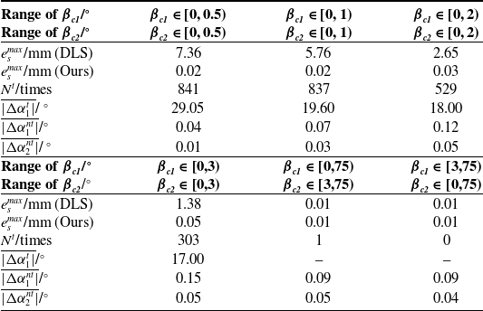
Table V presents the evaluation metrics, including the solving error
 $e_s$
, number
 $N^t$
of the triggered condition
 $e\gt \varepsilon ||\Delta b^{xy}||$
(
 $\varepsilon =0.2$
), mean absolute change
 $\overline {|\Delta \alpha _{1}^{t}|}$
of
 $\Delta \alpha _{1}$
under the triggered condition, and mean absolute changes
 $\overline {|\Delta \alpha _{1}^{nt}|}$
and
 $\overline {|\Delta \alpha _{2}^{nt}|}$
of
 $\Delta \alpha _{1}$
and
 $\Delta \alpha _{2}$
under the non-triggered condition. It is worth noting that the solving error
 $e_s$
is calculated using the following formula:
 \begin{equation} e_{s}=||b_t^{xy}-f_b(\Theta _t)|| \end{equation}
Statistical analysis of inverse kinematics test data.

It can be observed that as
 $ \beta _{c1}$
and
 $ \beta _{c2}$
approach zeros, failures in the DLS method become increasingly probable (as indicated by greatly increasing
 $ N_t$
and higher
 $ e_p^{max}$
). In contrast, the proposed algorithm demonstrates high solving accuracy across all experiment groups, with
 $e_s$
consistently approaching zero. Moreover, the variations in
 $ \alpha$
when the condition is triggered are significantly larger compared to when the condition is not triggered (Since the proposed algorithm compensates only for parameter
 $ \alpha _{1c}$
, only parameter
 $ \overline {|\Delta \alpha _{1}^{t}|}$
is analyzed under the triggered condition). These experimental results validate the proposed explanation for the occurrence of singularity and demonstrate that the proposed algorithm can effectively handle it. In addition, we add comparisons with the task-priority redundancy resolution and the modal methods, both of which are also commonly used singularity-robust inverse kinematics solvers [Reference Zhang, Du, Qin, Zhao and Yang30, Reference Villalobos, Sanchez and Martell38]. Since their experimental results are unsatisfactory and of limited comparative value, they are included in the supplementary material.
To present the effectiveness of the proposed algorithm in trajectory planning, several illustrative examples are provided, as shown in Figure 8. Based on the reference paths, solution sequences are generated using both the DLS and proposed algorithms. The sequences are substituted into Eq. (14) to obtain the corresponding planned trajectories. The experimental result indicates that the trajectories generated by the DLS method exhibit significant deviations near the singular point, whereas the trajectories planned by the proposed algorithm remain consistently aligned with the reference paths.
Trajectory planning comparisons between the DLS and our inverse kinematics algorithms. The proposed algorithm effectively suppresses the potential risk of severe oscillations during movements near the singular point.

5.4. Trajectory tracking test
To test the CR’s capability in end-effector movement, a tracking experiment is conducted. The square paths are first marked on the grid paper. With reference to the radius of the laryngeal cavity, the side lengths are chosen to be 7, 10, 13, and 16 mm, respectively. The CR’s end-effector is teleoperated to follow the designated paths. To facilitate visualization, the plotted patterns are shifted to center around
 $O$
. The evaluation metrics include the mean tracking error
 $e_t^{mean}$
, relative mean tracking error
 $re_t^{mean}$
(with respect to the continuum module length), maximum tracking error
 $e_t^{max}$
, and relative maximum tracking error
 $re_t^{max}$
. The tracking results are shown in Figure 9(b.1)–(b.4). Influenced by factors such as system hysteresis and cross-talk, the motion of the CR may occasionally deviate slightly from the predetermined trajectory. However, with visual feedback, the movement direction can be promptly adjusted. Ultimately, the CR achieves smooth and complete tracking of the predetermined trajectories, with the average tracking error controlled within 0.9 mm, as presented in Table VI.
Trajectory tracking experiment. (a.1)-(a.2) Tracking demonstration under no-load and load conditions. (b.1)–(b.4) Tracking results of
 $7\times 7$
,
 $10\times 10$
,
 $13\times 13$
, and
 $16\times 16$
square paths based on teleoperation. (b.5) Tracking result of the
 $16\times 16$
square path with a 50 g weight. (b.6) Tracking result of the
 $16\times 16$
square path based on closed-loop control.

Statistical analysis of trajectory tracking.

To further assess the system’s robustness against disturbances, a 50 g load is attached to the end-effector, and the
 $16\times 16$
square trajectory is tracked again, as shown in Figure 9(b.5). While a slight decrease in accuracy is observed compared to the unloaded condition, the average tracking error remains 1.00 mm, and no oscillations are detected. Therefore, even in the presence of disturbances from hysteresis, cross-talk, or load, the teleoperation based on visual feedback is capable of suppressing the perturbations, ensuring the feasibility of clinical operations. In addition, a closed-loop controller (proportional control) based on the proposed kinematic algorithm is developed and tested on the
 $16\times 16$
square trajectory, as shown in Figure 9(b.6). Despite minor jitter, the controller exhibits excellent tracking accuracy. Collectively, both visual feedback-based teleoperation and closed-loop control can effectively mitigate disturbances arising from factors such as hysteresis and cross-talk effects. The experimental results demonstrate that the proposed CR system exhibits strong end-effector tracking performance. During the tracking, no motion planning failures occur, demonstrating the robustness of the proposed inverse kinematics algorithm.
In addition, the average solving time of the inverse kinematics algorithm is 48 μs during the tracking. The end-to-end delay, including motion planning, inverse kinematics computation, and the CR’s initiation of movement, is only 63 μs. Such real-time performance is fully capable of meeting the requirements of laryngeal surgery.
5.5. Cross-talk test
The experiment is conducted to evaluate the cross-talk effect between PS and DS. To visually demonstrate the cross-talk state, keep one segment stationary while bending the other segment. First, the effect of PS bending on DS is tested. DS is controlled to remain at 0°, while PS bends to 60°in both the horizontal and vertical planes. The mean absolute end position error
 $e_c^{mean}$
of DS relative to PS is used as the evaluation criterion. The effect of DS bending on PS is tested in the same manner. After ten repeated experiments, the experimental results are shown in Figure 10 and Table VII.
 $e_c^{mean}$
does not exceed 1 mm. Based on the trajectory tracking experiment results, disturbances caused by cross-talk effects can be effectively suppressed by visual feedback-based teleoperation or closed-loop control strategies.
Cross-talk error.

Cross-talk effect demonstration. (a) PS bending, DS not moving. (b) DS bending, PS not moving.

Tube intervention test. (a.1)–(a.4) Tube intervention process of the manipulation arm based on the overall and segmented models. (b.1)–(b.8) Target contact process based on the overall and segmented models. (c.1)–(c.3) Tube intervention process only based on the overall model. (c.3) Illustrates the failed intervention result. (c.4) Target contact failure only based on the overall model.

5.6. Tube intervention test
This test is conducted to evaluate the ability of the manipulation arm to access and operate within the laryngeal cavity. A transparent tube with an inner diameter of 25 mm and an opening angle of 120
 $^\circ$
is used to simulate the laryngeal cavity. As shown in Figure 11(a.1)–(a.4), the gripper without bending capability is mounted at the end of the continuum module. Despite the reduced flexibility caused by the long rigid gripper, the manipulation arm successfully navigates into the tube through coordinated control of bending angles in the overall or segmental modes. In addition, to compare the advantages of the proposed system with the one-segment configuration, the manipulation arm is controlled again only in the overall mode, as shown in Figure 11(c.1)–(c.3). The manipulation arm is unable to enter the tube as a result of interference with the inner wall.
Then, the gripper is removed. Fifteen rectangular markers, each measuring 6 mm in length, are randomly attached to the sidewall of the tube. As shown in Figure 11(b.1)–(b.5), the manipulation arm is guided into the tube and used to touch these markers with its end-effector. The experiment is repeated with the tube rotated, as illustrated in Figure 11(b.6)–(b.8). Ultimately, by adjusting the bending angles and directions, the end successfully contacts all markers. In contrast to the two-segment configuration, the one-segment setup exhibits 3 instances of failure. One failure is shown in Figure 11(c.4). These results demonstrate that the two-segment configuration provides enhanced flexibility for accessing the laryngeal cavity and enables more dexterous manipulation.
5.7. Phantom test
Phantom experiment. (a)–(b) Oral intervention process of the manipulation arm. (c)–(e) Laryngeal intervention process of the manipulation arm. (f)–(h) Endoscopic view adjustment process of the manipulation arm.

A phantom test is conducted to verify the feasibility of the proposed CR in laryngeal examination. The phantom (DM-CS6279, DM MODEL, China) accurately simulates the larynx and its lesions. The endoscope equipped with LED lights is fixed to the end of the CR. Figure 12(–.1) and (–.2) represent the external camera and endoscope view, respectively. Initially, the CR is advanced into the oral cavity via the linear slide, as shown in Figure 12(a) and (b). Figure 12(c)–(e) shows the laryngeal intervention process of the manipulation arm. Considering that the laryngeal cavity roughly follows a C-shaped curve, the overall bending mode is employed as the primary movement pattern of the arm, accompanied by advancement via the linear slide. Subsequently, the arm switches to the segmented mode, and the DS angle parameters are adjusted to slightly move the end-effector, enabling a more precise intervention. To clearly present the lesions within the endoscopic view, the end-effector position is used as the control parameter. Specifically, during the process from Figure 6(e)–(h), the motion primarily occurs along the
 $-X_D$
and
 $Y_D$
directions, accompanied by slight adjustments of the linear slide. Ultimately, all lesions are clearly visualized. The entire process takes no more than 120 s, during which the CR has no collision with human tissue. The experimental results indicate that the CR facilitates rapid lesion inspection and localization in laryngeal surgery.
5.8. Animal test
To evaluate the performance of the CR system in the real scene, an animal test is conducted. The distal end of the CR system is guided to the entrance of the subject’s oral cavity via the collaborative robot. The experiment is guided by professional surgeons. The experiment primarily consists of two parts: oral and laryngeal intervention, as well as laryngeal manipulation. The operator successfully guides the manipulation arm into the oral and laryngeal by adjusting the movement of the linear slide and the bending and deflection angles of the continuum module. Figure 13(a.1)–(a.4) illustrates the process of the manipulation arm entering the oral cavity, while Figure 13(a.5)–(a.8) depicts its intervention in the larynx. In the laryngeal manipulation, the end-effector position of the manipulation arm serves as the controlled variable, approaching targets. Then, the gripper is used to grasp the targets. Figure 13(b.1)–(b.3) illustrates the process of grasping the lateral wall of the larynx from an endoscopic view. Figure 13(b.4) shows the grasping from an external view.
Animal experiment. (a.1)–(a.4) Oral intervention process of the manipulation arm. (a.5)–(a.8) Laryngeal intervention process of the manipulation arm. (b.1)–(b.3) Endoscopic view of laryngeal manipulation process. (b.4) External view of laryngeal manipulation.

Comparison with state-of-the-art CR systems.

The experimental result demonstrates the practicality and flexibility of the proposed CR system in laryngeal surgery. Throughout the CR’s operation, no motion planning failures occur, thereby validating the reliability of the inverse kinematics algorithm. No injuries caused by excessive contact forces occur. The entire animal experiment lasts two hours, during which the CR system exhibits no issues such as power failure, motor communication errors, or motion malfunctions, demonstrating its robustness and reliability.
5.9. Discussion
Table VIII summarizes the performance comparisons of the work in this paper with the state-of-the-art. Given the substantial differences among CR systems in terms of structure and intended clinical applications, it is not appropriate to directly compare algorithmic metrics such as calibration performance or inverse kinematics accuracy. Therefore, the comparison and discussion in this subsection are primarily conducted from a functional perspective. Regarding flexibility, the continuum module of our CR has 4 flexible DOFs, which is the highest. To avoid collisions between the CR’s drive system and the human body, remote actuation is essential. The ability to directly control the end-effector position helps doctors with operations. In addition, among all CR systems, only ours achieves automatic calibration. Such functionality contributes to shortening the preoperative preparation process. In summary, our CR has advantages regarding flexibility, locomotion, and ease of operation.
6. Conclusion
In this paper, a novel CR system with a robust inverse kinematics algorithm and a sensorless automatic calibration method is proposed for laryngeal surgery. The proposed CR system offers sufficient surgical DOFs, enabling both angle-based and end-effector position-based control. The inverse kinematics algorithm is proposed to address the singularity of the curvature hypotheses. Compared with the DLS method, the algorithm effectively mitigates the disturbance, reducing the maximum solving error from 7.36 to 0.05 mm. The suppression of the singularity ensures the continuity of motion planning. The calibration algorithm enables efficient and automatic calibration of the initial state without additional sensors, which reduces human intervention and shortens the preparation time for laryngeal surgery. The average calibration error is 1.23 mm. Compared with the manual calibration, the calibration time is reduced by approximately 160 s. The tube intervention experiment represents the CR’s capability for dexterous movement within narrow and curved cavities. The phantom and animal experiment results demonstrate the flexibility, practicality, and reliability of the proposed CR system for laryngeal surgery.
In future work, we will proceed along two directions. On the one hand, we will optimize the system design to integrate additional surgical instruments (such as suction channels and electrocautery devices) in a modular and interchangeable manner, thereby enhancing clinical practicality. Furthermore, fiber Bragg grating (FBG) sensors will also be integrated to enhance perceptual capability during tissue interaction. On the other hand, we will design a robust controller to further mitigate disturbances arising from tendon hysteresis and cross-talk effects.
Supplementary material
The supplementary material for this article can be found at https://doi.org/10.1017/S0263574725102725.
Author contributions
Sihan Zhao proposed the modeling and calibration methods and wrote the manuscript. Rui Tao designed the robotic system. Yichen Fu and Jun Hou participated in the animal experiment. Yunkai Ma, Junfeng Fan, Fengshui Jing, and Gui-Bin Bian reviewed the manuscript.
Financial support
This work was supported by the National Key Research and Development Program of China under Grant 2023YFB4706800; the National Natural Science Foundation of China under Grant 62173327; the China Postdoctoral Science Foundation under Grant Number 2024M763536.
Competing interests
The authors declare no conflicts of interest exist.
Ethical approval
This work involved animals in its research. Approval of all ethical and experimental procedures and protocols was granted by the Peking University First Hospital Laboratory Animal Center under Applicant No. J2025041.