I. INTRODUCTION
Polarization has a great influence in determining the performance of communication systems. In fact, multipath reflections can vary the polarization of the propagating signal. However, this is not challenge if both of transmitter and receiver antennas are circularly polarized, and polarization alignment is ignored. Planar circularly polarized (CP) antennas have obvious features such as lightweight, low-profile and ease of fabrication that highly suitable for wireless communications. Circular polarization is constructed by exciting two orthogonal modes in antennas. In conventional patch antennas, axial-ratio (AR) bandwidth is unacceptable (narrow bandwidth due to inherent characteristics). The printed CP slot antennas have very interesting capabilities for providing wide impedance and axial-ratio (AR) bandwidths, while it maintains the low profile. Different methods are used to feed these antennas that microstrip lines and coplanar waveguide (CPW) are popular. Hitherto, many CP array antennas with various techniques to achieving circular polarization properties have been reported in [Reference Jin, Shen, Li and Alphones1–Reference Karamzadeh, Virdee, Rafii and Kartal10]. Some famous techniques are presented for obtaining CP feature in microstrip antennas, for example: (I) series feed [Reference Sood, Jyoti and Sharma11], (II) parallel feed [Reference Huang12], and (III) sequentially rotation feed [Reference Pourahmadazar and Rafii13]. Two first types of these methods are traditional and have many limitations such as: hard to realize and increased length of array in method I, unacceptable mutual coupling effect between elements and feed network and unbalanced pattern in method II. In recent years, many researches have been introduced the corporate-fed arrays consist of sequentially rotated method [Reference Jin, Shen, Li and Alphones1, Reference Dashti and Neshati2, Reference Sood, Jyoti and Sharma11–Reference Pourahmadazar and Rafii13]. The results show that great improvement in AR operation has been achieved.
The sequentially rotated feed technique has many advantages in comparison of traditional coplanar corporate feed. These types of feeds improve the bandwidth, radiation pattern and execute purity in polarization efficiency over a wider frequency band. But, 3 dB AR bandwidth of arrays is restricted and usually <20%. For enhancing this failure the CP element is used. Also using CP element causes to have grater gain and balanced radiation pattern. Using sequentially rotated feed technique and reducing destructive mutual coupling among array elements is one of the most popular methods for exciting the CP array, but the gain of this technique is relatively low [Reference Rafii, Nourinia, Ghobadi, Pourahmadazar and Virdee9, Reference Karamzadeh, Virdee, Rafii and Kartal10]. Two main reasons decrease the gain of proposed antenna array. First, large amount of substrate current distribution and the second is high value of cross-polarization. Using cavity back substrate-integrated waveguide (CBSIW) slot antenna detract cross-polarization and mutual coupling between antenna elements and results to enhance the overall performance of sequentially rotated feed network in CP antenna arrays [Reference Dashti and Neshati2–Reference Shiqiang, Shaojun, Wang and Li7]. In this work, a novel broad band 2 × 2 antenna array by sequentially rotated feed is presented. Multi-layer SIW cavity back CP single element, has a relatively improved gain and low mutual coupling. The technique employed here to overcome decreasing in the AR bandwidth and enhance the purity of circular polarization consists of sequentially rotating the radiation elements in the array with respect to each other. For improving the overall gain of antenna array the CBSIW elements and combination of microstrip lines with different characteristic impedances at feeding network are utilized. Measured results illustrate that the fabricated antenna array has a 3 dB AR bandwidth of 2.1 GHz that extends between 9 and 11.05 GHz, and impedance bandwidth of 2.8 GHz between 8.7 and 11.5 GHz. Antenna gain is more than 15 dBi between 9 and 11 GHz. In different sections, the details of antenna configuration, simulation, and practical results are extracted and discussed. This paper is organized as follows. Section II describes the design and configuration of the SIW CP antenna element. Section III explains the design of the CP 2 × 2 antenna feed network. In Section IV, measured results are presented and discussed. Section V gives the conclusions.
II. SINGLE ELEMENT DESIGN
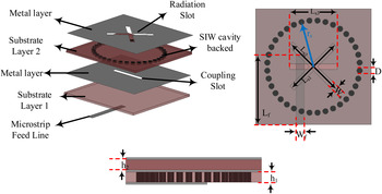
Figure 1 shows the geometrical configuration of the proposed CP single element. The antenna element is consisted of two layers that the top layer is RT/duroid 5880 with relative permittivity ε r = 2.2 and bottom layer is Rogers 4003 with relative permittivity ε r = 3.55, while both thickness are (=h) 0.508 mm. As shown in Fig. 1, element fed by aperture couple technique leads to isolate feed line and radiated antenna. At upper layer of top substrate, an X-shaped slot is clipped that provides CP conditions. The microstrip widths are set to 1.5 mm for 50 Ω characteristic impedance. All optimized parameters of proposed antenna are shown in Fig. 1. Parameters of the antenna element are optimized by High Frequency Structure Simulator (Ansoft HFSS v.15). Radius of the circular SIW cavity can be calculated by following formula (1), where B11 is the first root of the first-order Bessel function, and ε r is the permittivity of the substrate [Reference Dashti and Neshati14].
 $${r_s} = \displaystyle{{{\lambda _0}} \over {2.7\pi \sqrt {{\varepsilon _r}}}} {B_{11}}.$$
The average length of the slot is roughly a half equivalent resonant wavelength. Each slot length is equal to the average length with a slight difference. Its calculating formula is
 $${L_{S1,2}} = \displaystyle{{{\lambda _0}} \over {1.5\sqrt {{\varepsilon _r} + 1}}} \pm 1.1\displaystyle{h \over {\sqrt {{\varepsilon _r} + 1}}}.$$
Right-hand circular polarization or left-hand circular polarization (LHCP) radiation can be achieved by setting L s1 less or more than L s2 [Reference Luo, Hu, Liang, Li and Sun5].
Configuration of SIW cavity back slot antenna (W f = 1.1, L f = 13, L s1 = 11, L s2 = 10.5, L s3 = 8.2, W s = 1, r s = 8, D = 1, and t = 1.2, all value in mm).

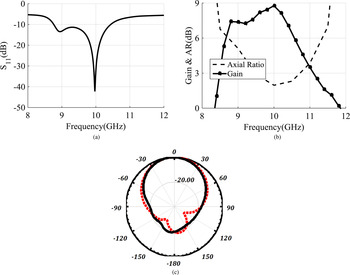
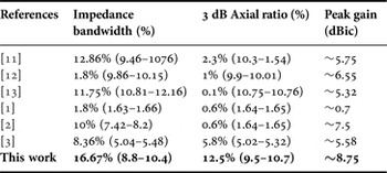
To attain a deeper insight of how the antenna's parameters influence its performance, a parametric study was necessary. The simulated return loss curve is illustrated in Fig. 2(a). The impedance bandwidth is from 8.8 to 10.4 GHz. The 3 dB AR is depicted in Fig. 2(b), it is obvious that the bandwidth is 1.2 GHz and wide speared from 9.5 to 10.7 GHz. Simulated radiation pattern of single element cavity back antenna at minimum value point of AR (10 GHz) is demonstrated in Fig. 2(c). The comparison of proposed element with previously reported SIW cavity back slot antennas is displayed in Table 1.
(a) Simulated return-loss of a single-element. (b) Simulated gain and AR. (c) Simulated LHCP radiation pattern at 10 GHz (straight line φ = 0° and dash line φ = 90°).

Comparison of proposed single element with same work.

III. FEED NETWORK DESIGN
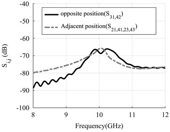
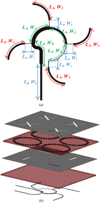
The array antenna is fed by sequentially rotated feed network. Configuration of the array network was designed and simulated by using Agilent™ Advance Design commercial software System. The proposed CP feed network consists of seven quarter wavelength transformers are linked together in a sequential rotated form with alternative parallel and series connections to form a four port network. Ports 1–4 are output ports, which are connected to respective microstrip patch elements with their impedance Z = 50 Ω (as shown in Fig. 4(a)) consequently, all elements are positioned symmetrically and realizing a circular polarization with sufficient purity is expected. Seven quarter-wave transformers were designed in a circular shape, to reduce the discontinuity. Hence, the network produces a phase shift of 90 and equal power split between adjacent output ports. In the other words, the signal amplitudes at output ports are theoretically identical, but there is a 90 phase difference among two adjacent ports [Reference Rafii, Nourinia, Ghobadi, Pourahmadazar and Virdee9, Reference Karamzadeh, Virdee, Rafii and Kartal10]. As mentioned in the previous section, use of aperture couple technique and CBSIW slot antenna, reduced cross-polarization and mutual coupling in antenna elements. Despite having been, metalized via between two radiated elements, acts like a conductor wall, which is caused to reduce mutual coupling. Figure 3 shows the mutual coupling between elements. It is clear that the result is acceptable and its value less than −65 dB. Figures 4(a) and 4(b) describe the feed network and final antenna, respectively.
Simulated mutual coupling between the array elements.

(a) Configuration of the sequentially rotated feed network: L 1 = 12, L f = 13.3, L t = 2.1, W 0 = 0.9, W 1 = 0.25, W 2 = 1.2, W 3 = 1, W 4 = 0.01, W f = 1.1, and W t = 0.01 (all value in mm) (L 1 = 90°, W 1 = 100 Ω, Lt ≈ 16°, W 4 = W t = 200 Ω, W 3 = 141 Ω, W 2 = 82 Ω, and W 0 = 58 Ω). (b) Photograph of the double-layer array antenna structure.

IV. MEASURED RESULTS AND DISCUSSION
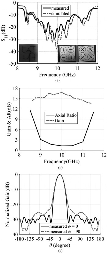
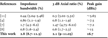
The schematic of proposed array is shown in Fig. 4(b). In this figure, the space between elements is 0.7λ 0 (λ 0 = wavelength in free space). Scattering parameters are measured by Agilent™ 8722ES vector network analyzer. Comparison of simulated and measured results is illustrated in Fig. 5(a). The impedance bandwidth is agreeable and acceptable correlation between extracted results is obtained. Peak gain and AR curves are illustrated in Fig. 5(b). The 3 dB AR bandwidth is from 9 to 11.05 GHz, while the minimum value is 1.8 dB at 10 GHz. The average value of measured gain is about 15.5 dBic and the maximum value is 16.7 dBic at center frequency of X-band. The theoretical maximum gain of array (for 2 × 2 layout) should be <15 dB, but by combining thin length of line with wide length of line in sequentially rotated feed network, as shown in Figs 1 and 4, the resonance (impedance matching) is enhanced. Therefore antenna radiation resistance is increased and leads to improve radiation efficiency and overall gain. Finally, antenna array can provided high gain of 16.7 dB at 10 GHz frequency. Normalized measured patterns are displayed in Fig. 5(c). Half-power bandwidth is 27.2° and side lobe level is less than −25 dB. Comparison between the proposed antenna and same works that were fed by arc feed-line is presented in Table 2.
(a) Comparison between the simulated and measured return loss for the fabricated antenna. (b) Measured gain and AR. (c) Measured LHCP radiation pattern at 10 GHz (straight line φ = 0° and dash line φ = 90°).

Comparison of proposed feed network structure and measured characteristics with other array antennas.

V. CONCLUSION
This paper presents a novel broad band and compact array antenna with 2 × 2 sequentially rotated feed network. Use of SIW metallic vias and sequentially rotated feed network reduced mutual coupling among antenna element less than −65 dB. By inserting X-shape slots, CBSIW antenna impedance bandwidth is approximately 16.67%, while 12.5% fractional bandwidth for CP realization is achieved. Using the appropriate rotation technique, impedance and AR bandwidths are effectively enhanced. The fabricated array with very low side lobe level and broadband impedance bandwidth will be employed in radar, satellite, and other wireless systems that operating in X-band application. A novel technique for increasing gain of antenna is reported. The proposed array with its specific feed network is remarkable choice for smart wireless communications.
 Mir. Majid- Fakheri was born in Urmia, Iran, in 1984. He received the B.Sc. degree in Telecommunication Engineering from IAU University, Urmia, Iran in 2006, and M.Sc. degree from Urmia University, Iran in 2010. Since 2010, He has been with IAU University working at Telecommunications Department in faculty of Electrical and Computer Engineering. He has been a Ph.D. student in Telecommunication Engineering in SRBIAU University since 2011. His current interests are numerical techniques in electromagnetic, antenna, propagation, neural network, pattern recognition, image processing, substrate integrated waveguide (SIW), and array antenna.
 Mohammad Naser-Moghadasi was born in Saveh, Iran, in 1959. He received the B.Sc. degree in Communication Engineering in 1985 from the Leeds Metropolitan University (formerly Leeds polytechnic), UK. Between 1985 and 1987 he worked as an RF design engineer for the Gigatech Company in Newcastle Upon Tyne, UK. From 1987 to 1989, he was awarded a full scholarship by the Leeds educational authority to pursue an M.Phil. Studying in CAD of Microwave circuits. He received his Ph.D. in 1993, from the University of Bradford, UK. He was offered then a 2 years Post Doc. to pursue his research on Microwave Cooking of Materials at the University of Nottingham, UK. From 1995, Dr. Naser-Moghadasi joined Islamic Azad University, Science & Research Branch, Iran, where currently he is an Associate Professor and Head of postgraduate studies. His main areas of interest in research are Microstrip antenna, Microwave passive and active circuits, and RF MEMS. Dr. Naser-Moghadasi is the member of the Institution of Engineering and Technology, MIET and the Institute of Electronics, Information and Communication Engineers (IEICE). He has so far published over 160 papers in different journals and conferences.
 Ramezan Ali- Sadeghzadeh received the B.Sc. degree in Telecommunication Engineering from K. N. Toosi University of Technology, Tehran, Iran, in 1984, the M.Sc. in Digital Communication Engineering from the University of Bradford, Bradford, UK, and University of Manchester Institute of Science and Technology (UMIST), Manchester, UK, as a joint program in 1987, and the Ph.D. degree in Electromagnetic and Antenna from the University of Bradford in 1991. During 1992–1997, he worked as a Postdoctoral Research Assistant in the field of propagation, electromagnetic, antenna, biomedical, and wireless communication at the University of Bradford. From 1984 to 1985, he was with Iran Telecommunication Company, Tehran, Iran, working on networking. Since 1997, he has been with the Faculty of Electrical and Computer Engineering, K. N. Toosi University of Technology. He has published more than 120 referable papers in international journals and conferences. His research interests include numerical techniques in Electromagnetics, antenna, propagation, radio networks, wireless communications, Nano antennas, and radar systems.