I. INTRODUCTION
Wireless power transfer (WPT) was first demonstrated by Nikola Tesla in the 1890s. Today WPT and its associated technologies represent a dynamic industry that is actively growing and innovating to harness tangible benefits in real-world applications. One of the most common technical concepts under the topic of WPT is inductive power transfer (IPT), which relies on the mutual inductance between two spirals to deliver electrical power without any electrical connection [Reference Trevisan and Costanzo1].
In another trend, new materials enable new lightweight strategies which allow the integration of multiple functions into one structural component. Carbon-fiber-reinforced plastics (CFRP), or simply composites, are materials known for having the best strength-to-weight ratio. Exploiting the electrical properties of carbon fiber and precision of tailored-fiber placement (TFP) processes can allow for multi-functional integration of antenna functions into a CRFP part. This hypothesis has been tested and proven in the work of Horoschenkoff [Reference Horoschenkoff and Christner2] by creating a complete carbon-composite radio frequency identification device. Applications of such integration can include monitoring and tracking in lightweight constructions or use in environment where the oxidation of metallic contacts is problematic to system function.
The goal of this research is to create multifunctional materials in the integrated and scalable production process known as TFP via embroidery machines. Potential industrial applications include consumer electronics, sensory systems, and bio-medicine. To prove this concept, carbon-fiber antenna prototypes have been specifically designed and produced by means of a technical embroidery machine. After which the produced prototypes, and methods thereof, have been characterized in order to judge technological viability and manufacturability. The final goal is to provide recommendations to the functionality and manufacturability of the presented technology.
II. EXISTING TECHNOLOGY
This section elaborates upon the two introduced technologies of WPT and fiber-reinforced composite materials, as well as their branches.
A) Wireless power transfer
The presented work distinguishes its nomenclature according to the work of Trevisan and Costanzo [Reference Trevisan and Costanzo1]. Contactless energy transfer (CET) refers to the larger scope of the technology and its applications. WPT is then a subset of intended use of the presented technology, e.g. wireless charging. Furthermore, IPT is the functional operating state of the presented technology.
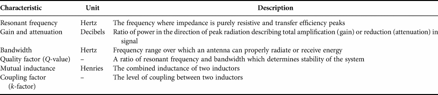
The functional basis of a wireless power system involves two coil antennas – a transmitter (Tx) and receiver (Rx). Taking advantage of the principle of electromagnetic (EM) waves, a transmitter coil that is energized by an alternating current generates a magnetic field, which in turn induces a current in a nearby receiver coil. The coils created in this work are a form of wire antennas which are a single-layer spiral shape, thus will be referred to from here as “spirals”. The fundamental characteristics of the spiral antennas tested in this paper are listed in Table 1 [Reference Balanis3].
Fundamental characteristics of spiral antennas tested in this work.

To describe the spiral as an inductor, one could call it a flat spiral with an air core. An inductor is defined as a passive element in an electrical circuit which stores electrical energy in the form of a magnetic field when current flows through it.
1) INDUCTIVE SPIRALS
IPT, a low-frequency and high-efficiency transfer mechanism, depends on the self- and mutual inductance of two spiral antennas for CET. Mutual inductance of two spiral antennas is a description of electromagnetically coupled inductors. The more coupling between two units, the more flux reaches the Rx spiral, thereby increasing the power transfer efficiency, i.e. resulting in more usable power instead of EM emissions. The coupling factor k between two inductors is determined using the self-inductance of each inductor as well as the mutual inductance between the two. In equation (1), L 1 and L 2 refer to the self-inductance of the transmitting and receiving spirals, respectively, and M is the mutual inductance between the two spirals for a given arrangement [Reference Trevisan and Costanzo1, Reference Fischer, Farley, Gao, Bai and Tse4–Reference Hassan and Elzawawi6].
 $$M = k\sqrt {L_1L_2}. $$
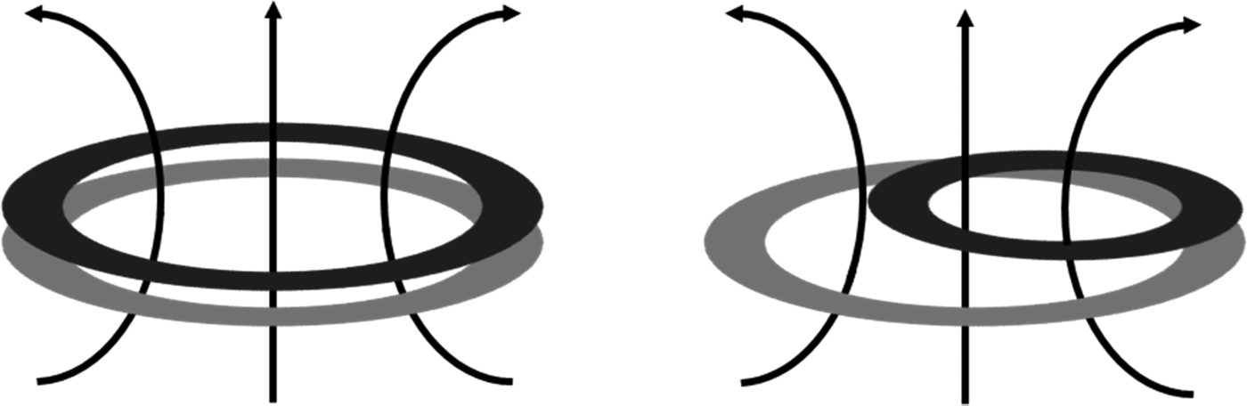
This unit-less coupling factor depends on physical antenna parameters such as number of turns, cross-section area, spiral length, as well as the relative permeability of the substance separating them (plastic and/or air). When determining the IPT performance of two spirals, the transfer distance and efficiency are the most critical factors, and they are directly related to dimensions of the Tx and Rx spirals [Reference Hassan and Elzawawi6, Reference Heo, Choi, Kim, Park and Lee7]. An illustration of these described effects can be seen in Fig. 1.
Illustration example of tightly coupled inductors (left) and loosely coupled inductors (right) with magnetic field flow between them.

B) Textile engineering and composites
Composite materials consist of two major system components, a reinforcement and a matrix. The reinforcement is typically long, high-performance textile fiber (carbon, glass, aramid, etc.) and the matrix is either a thermoset (epoxy resin, vinyl ester, etc.) or a thermoplastic (PP, PA6, etc.). This symbiotic functioning works because the matrix material holds the fibers in place which have the strength to take loads in structural applications. Carbon fiber, besides being widely used and known for excellent physical properties, is multifaceted with electrical properties as well, which are seldom capitalized in composite applications.
1) CARBON FIBERS
Carbon fibers themselves are defined by Safarova and Gregr [Reference Safarova and Gregr8] as a fibrous carbon material that is transformed from organic matter at temperatures ranging from 1000 to 1500°C. Almost all hydrogen and nitrogen components are removed leaving a thread of graphite fibers which individually shrink to a diameter of 7 µm. They have imperfect graphite crystalline structure arranged along the fiber axis and carbon content >90% [Reference Anderson9]. Finished carbon-fiber tow is characterized by its number of thousand filaments per tow (e.g. 24k) and by its fineness (Tex), which is a textile parameter for weight per linear unit density.
Electrical resistivity of carbon-fiber tows typically varies due to the deviations in composition and structure related to the conditions of their production and to impurities present in their structure. The four major points of production that influence electrical resistivity of carbon fibers are the types of precursor material (either polyacrylonitrile or pitch), the parameters of fiber formation and orientation stretching, the level of carbonization, plus the chemical coating called sizing which protects the fibers during handling [Reference Safarova and Gregr8]. An advantage of carbon fiber over metal is that it does not produce an oxidizing coating. This leads to a higher contact conductivity over long periods of time [Reference Anderson9].
Since the fiber orientation within the matrix determines much of the component's strength characteristics, various manufacturing methods to produce composite materials focus on design-based orientation of the fibers before matrix impregnation. In many cases, a so-called preform is first manufactured, which is a near-net (near-final) shape, dry-fiber component. The technological process which offers the best combination of these advantages with high precision and scalability is called TFP.
2) TFP WITH EMBROIDERY MACHINES
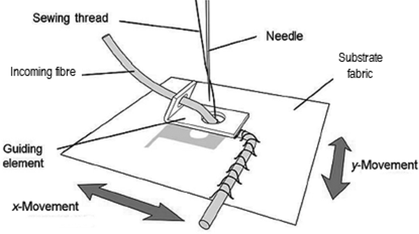
TFP with technical embroidery machines, visualized in Fig. 2 by Gries et al. [Reference Gries, Veit and Wulfhorst10], is a process where a fiber roving is placed in a highly specific geometry onto a substrate fabric and joined by top and bottom interlocking sewing threads, typically polyester. The stiches hold the design firmly to a substrate fabric which is usually a simple, frame-tensioned, non-woven, or fleece. The frame movement is computer controlled in the x- and y-directions to create a zig-zag stitch that secures the roving. When the needle punches through the fabric, the lower thread is interlaced with it by a rotating gripper underneath the fabric. Since the needle is stationary, patterning is facilitated by the movement of the substrate fabric and a rotating head (guiding element) [Reference Gries, Veit and Wulfhorst10–Reference Mattheij, Glieschie and Feltin12].
Visualization of the TFP embroidery process.

The benefits of near-net shape preform are highly oriented product designs for manufacturing and performance, plus economical and sustainable usage of expensive textile materials such as carbon and ceramic. TFP composite preforms are popular for key structural components in high-end automobiles, smart textiles in consumer products, and medical prosthetics. The precision and flexibility of these machines could allow an integrated process step which stiches a spiral in a part to act as an inductor in CET.
III. PROPOSED TECHNOLOGY
Given the context of the existing technologies, it was hypothesized that the inherent conductive abilities of carbon fibers can be exploited if TFP embroidery machines were able to precisely stitch the spiral form of the common antenna. This chapter will start with the design considerations necessary for such a feat, then directly describe the manufacturing process of the carbon-antenna preforms as well as the carbon-composite antennas.
A) Design and preform production
Within the framework of this experiment “off-the-shelf” carbon roving is planned for use in order to demonstrate the ease of material procurement. Carbon material with 24k and a 12k tows were chosen to further demonstrate material functionality. For the planned antenna to produce a suitable magnetic field, it is important that the turns of the spiral are as close as possible. At the same time, it is necessary that there is no electrical contact between turns, which would create a short circuit, thus nullifying the inductive properties. In normal inductors, turn separation is usually achieved by isolating the wires in plastic or rubber coating and winding them directly on top of each other. While isolated carbon tow is not readily available, special care needed to be taken during the design phase in order to prevent electrical contact between the turns of the stitched pattern in the final prototypes.
The carbon-antenna prototypes were designed on a ZSK SGVA 0109-825 and produced on a ZSK MCSW 0100-1800 technical embroidery machine from ZSK Stickmaschinen GmbH in Krefeld, Germany. The only difference between the two being an environment equipped to work with carbon. Otherwise the two machines are functionally identical.
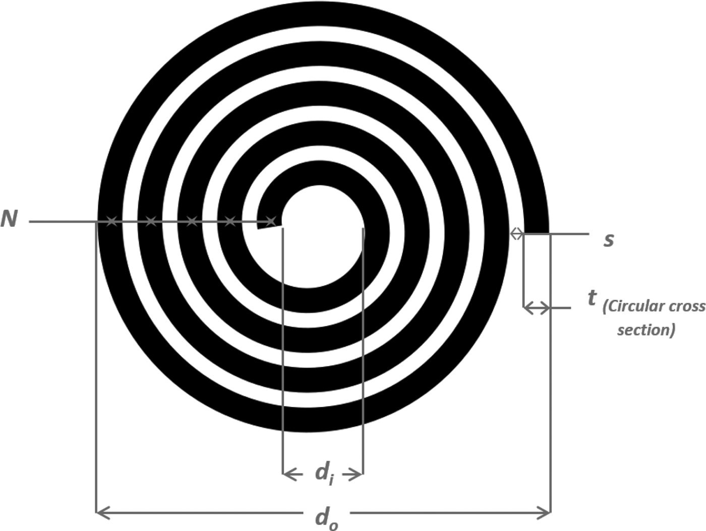
Through an iterative process, the minimal possible distance between turns, called pitch (s) that consistently prevented touching of the spiral turns was determined to be 0.8 mm. The diameter of the stitched 24k roving was measured to be 1.5 mm. Using these two values, spiral designs were made using the open-source program Inkscape, as shown in Fig. 3. The Inkscape templates were directly applicable into the ZSK machine programming.
Inkscape screenshot of spiral design with measurements.

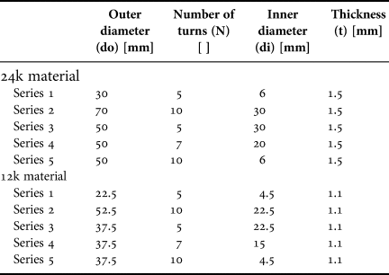
After the process capabilities of the machines were determined, standardized designs for wireless power antennas were reviewed in order to imitate the currently existing technology as closely as possible. The Wireless Power Consortium has a publicly available antenna specification called “Qi” (pronounced chi) for quality standards and reference designs. The document contains over 40 different antenna reference designs with information for physical dimensions, materials, shielding, electrical, and control parameters. Based on similar designs in Qi, the final dimensions of the antenna design are listed in Table 2.
Carbon-antenna prototype dimensions.

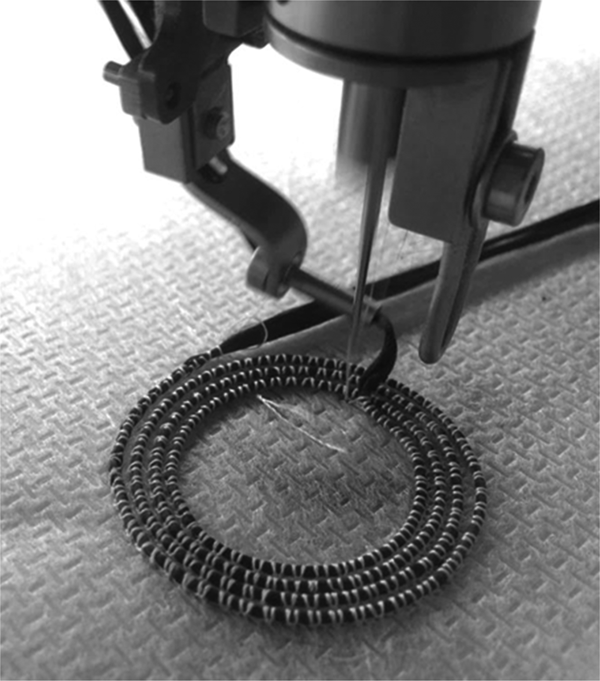
The final prototypes were designed using the constraints of the manufacturing process, combined with the goals of the Qi specification, with the outer diameter and number of turns as the independent variables. Five series of prototype designs were decided upon considering the 24k carbon tow. Since the 12k tow has half number of carbon filaments of the 24k tow, and half of the area results in a diameter reduction of about 75%, the same designs for 24k were simply scaled to 75% of their original size. Figure 4 shows the production of the carbon preforms on the ZSK embroidery machine.
Production of carbon-antenna prototypes.

B) Matrix impregnation
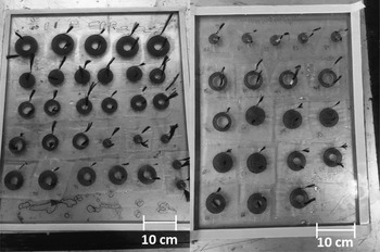
The final step of production was to turn the carbon-antenna preforms into composites by means of an epoxy resin, shown in Fig. 5. The resin system used was EPIKOTE Resin MGS RIMR426 from the company Lange + Ritter GmbH from Gerlingen, Germany, with a 100:26 ratio of EPURE Curing Agent MGS RIMH435. The two free-ends of each prototype were both fixed with crimping metal contacts to protect the fibers and hold the roving upward. After contacting, the first step of the process was to prepare glass plates with lining and release agent. The 50 prototypes described in Table 2 (five of each series) were then arranged on the glass plates as seen in Fig. 5.
Curing of the composite antennas.

The epoxy system was mixed and then applied to each prototype individually by first spreading resin under the antenna, then by brushing the antenna with resin so that the base fabric was completely saturated with no air bubbles, and to completely fill the turns of the antenna with resin. After 18 h of curing at room temperature and atmospheric pressure, the prototype samples were separated from the glass with the help of a sharp-edged tool.
IV. EVALUATION OF THE PROPOSED TECHNOLOGY
Several levels of testing were performed in order to holistically characterize the proposed technology. For a baseline analysis, the electrical resistivity of the carbon roving was performed. Then several levels of analysis of the antenna prototypes were carried out. First the resistivity of the carbon was determined and self-inductance of each sample was measured. Then a signal transfer test was performed using a wireless power design kit as a benchmark. The attenuation and resonant frequency were recorded.
A) Electrical resistivity of the carbon roving
Resistivity is a material property which can be used to compare how different materials resist electrical flow. In order to set baseline expectations for how a new material will function in IPT applications, the resistivity of the carbon roving was compared with the given manufacturer values. Resistivity is calculated as shown in equation (2) by taking a measured resistance (R) and multiplying it by the ratio of cross-sectional area (A) to length (l), producing the unit ohms times unit length.
 $$\rho = R\displaystyle{A \over l}.$$
For context, they are presented in Table 3 against accepted values for solid copper wire. The resistance test was carried out according to DIN EN 16812: “Determination of the linear electrical resistance of conductive tracks”. Five samples were used from each of the types of roving (24k and 12k) from the company Toho Tenax headquartered in Tokyo, Japan. The material designation is Tenax-E HTS40 F13. The measurements were taking using a standard LCR multimeter, Typ SW-8280 from the company ELV in Leer, Germany. The results of this test were used to calculate the resistivities shown in Table 3.
Results of carbon resistivity test proof.

* Resistance values are given for a length of 1 m material.
† The resistance value for copper is a given value.
As resistivity is a material property, the measured values should be the same for both the 24k and 12k carbon material. The measured difference between the two types of sample and from the given values is attributed to variations in the sizing chemicals applied to the roving plus an insufficient contacting method, thus explaining the high deviation from the given electrical resistivity. The results do however, speak of the potential capabilities of the prototypes. If the manufacturer's values are correct with quality sizing, and can be measured with proper contacting, the antennas will have a higher baseline performance. Then, more turns can be used with the same resistive equivalent circuit diagram at resonance.
B) Characterization testing of the carbon antennas
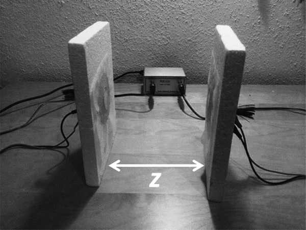
In order to quantitatively determine the functional characteristics of the carbon-antenna prototypes, tests were carried out using a 3E DG8SAQ type Vectors Analyzer from SDR-Kits. This device has a transmitting port and receiving port with coax connectors and generates frequencies from 20 kHz up to 1.3 GHz. Up until 1300 MHz, the signal produces a voltage of 225 mVrms. Using coax-BNC adapters, measuring lines tipped with alligator clips connects the carbon-antenna prototypes to the device. The vector network analyzer (VNWA) measures transfer of signals across the two ports in S-parameters of selected impedance forms. A visual of the device and general test set-up can be seen in Fig. 6. The free-ends of the antenna prototypes were connected to the respective Tx and Rx measurement lines through holes in the styrofoam plates. The substrate fabric then acts as a barrier so that the Tx and Rx antennas could lay directly on top of each other without causing short circuit. The styrofoam plates were held at close range with wooden pins to ensure alignment and protect against unwanted movement.
Vector network analyzer and general test set-up.

The VNWA must first be calibrated before use. Calibration must be done specifically for the frequency range and every time the measured range is changed. While performing the sanity check on frequency measurements with a wide range, there proved to be an inability of the equipment to accurately measure into the mid-MHz ranges (≤50 MHz). Between 10 and 50 MHz noise peaks reached as high as −14 up to −8 dB. When testing in this range, it would be difficult to distinguish the material functionality from the noise. This was attributed either to the sound cards that were in the computers used or resonance of the connectors used. Since the results were not trustworthy in this range, and it is regardless outside of the range of applications, the following tests with the VNWA were conducted in the range of 20 kHz to 5 MHz.
1) INDUCTANCE MEASUREMENTS
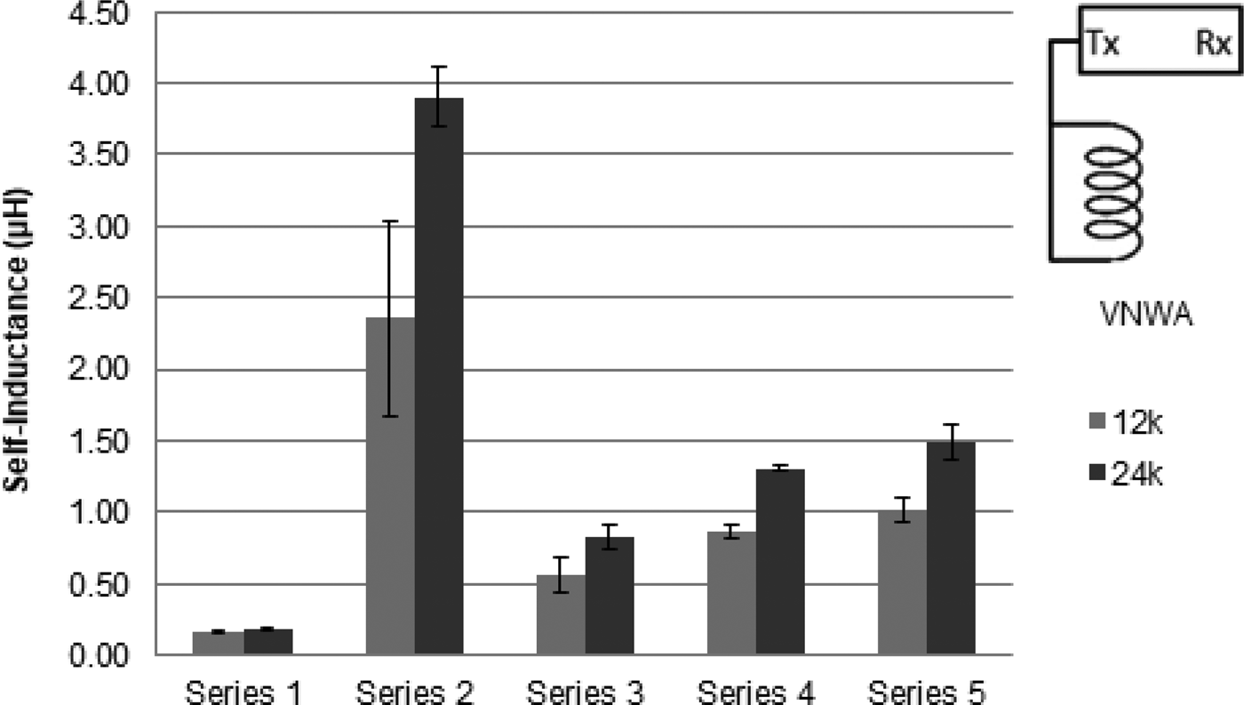
In order to have the proper measurement set-up for measuring inductance with the VNWA, the work of Stepins et al. [Reference Stepins, Asmanis and Asmanis13] was consulted. Stepins et al. review three different methods for measuring capacitance with a VNWA. Based on their discussion of value magnitudes, frequency ranges, and variability, it was determined that the reflection method would be the best way to measure inductance for this project. This method involves connecting the antenna only to the Tx measurement line and measuring the S 11 parameter. The validity of this method was tested with capacitors and inductors of known values. The reflection method was able to measure within 10% of a reported value. The inductance values were measured across the intended application range of 100–150 kHz and an average were provided. The sweep was run continuously five times before a reading was taken. The results are displayed in Fig. 7.
Average self-inductance of composite antenna versions across series number and material type.

Due to the size of the spirals, the self-resonant frequencies are known to be outside of the range of accurate measurement (~60 MHz); therefore, these values are not reported. The displayed results in Fig. 7 show some obvious expectations. The 12k samples have lower inductances because of the smaller conducting path. The series 2 samples had the highest inductance values because of their size. With a larger spiral there is simply more path for the current to travel and generate a stronger magnetic field. Series 3–5 show increasing inductance values, again because increasing the number of turns strengthens the magnetic field. The less drastic increase from series 4–5 as compared with series 3–4 is attributed to the fact that the inner diameter of the spiral in series 5 almost disappears due to the size and number of turns. Figure 10 shows a high standard deviation for the readings of series 2 with 12k material. This is because the sample series has two outliers which were consistently measured at significantly lower values. The source of this variation is undetermined.
2) SIGNAL TRANSFER TEST
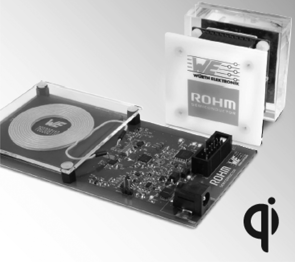
A benchmark test was performed using a wireless power design kit from the company ROHM Co., Ltd. headquartered in Kyoto, Japan and the company Würth Electronik GmbH & Co. KG headquartered in Niedernhall, Germany. The kit is an IPT device with LED lights attached to the receiver spiral in order to demonstrate its ability. A photo of the design kit with the Qi certification logo can be seen in Fig. 8.
WPT design kit for benchmark test.

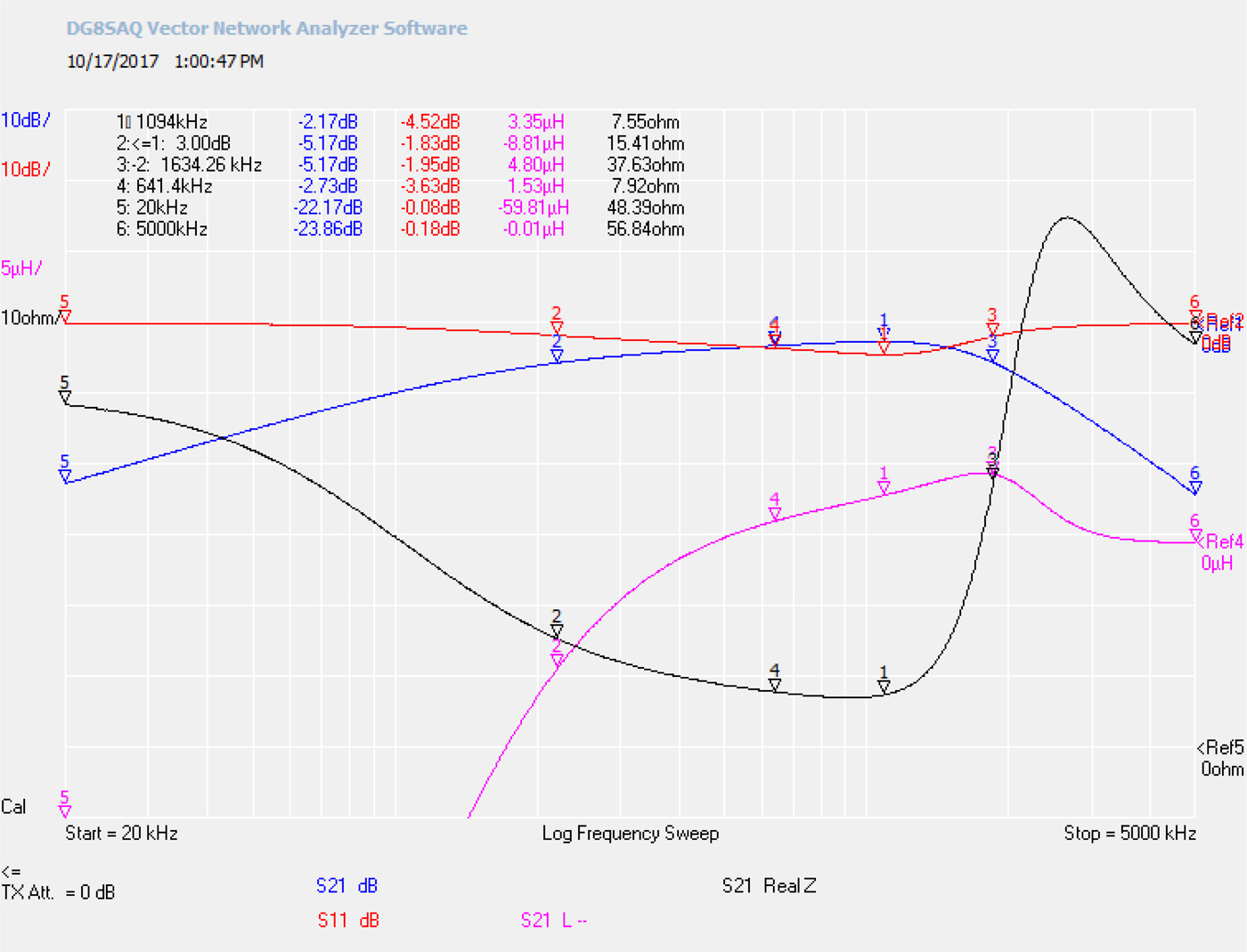
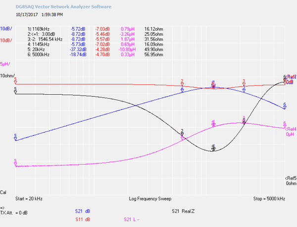
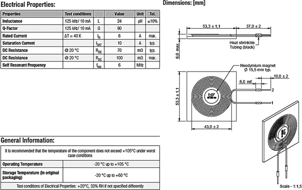
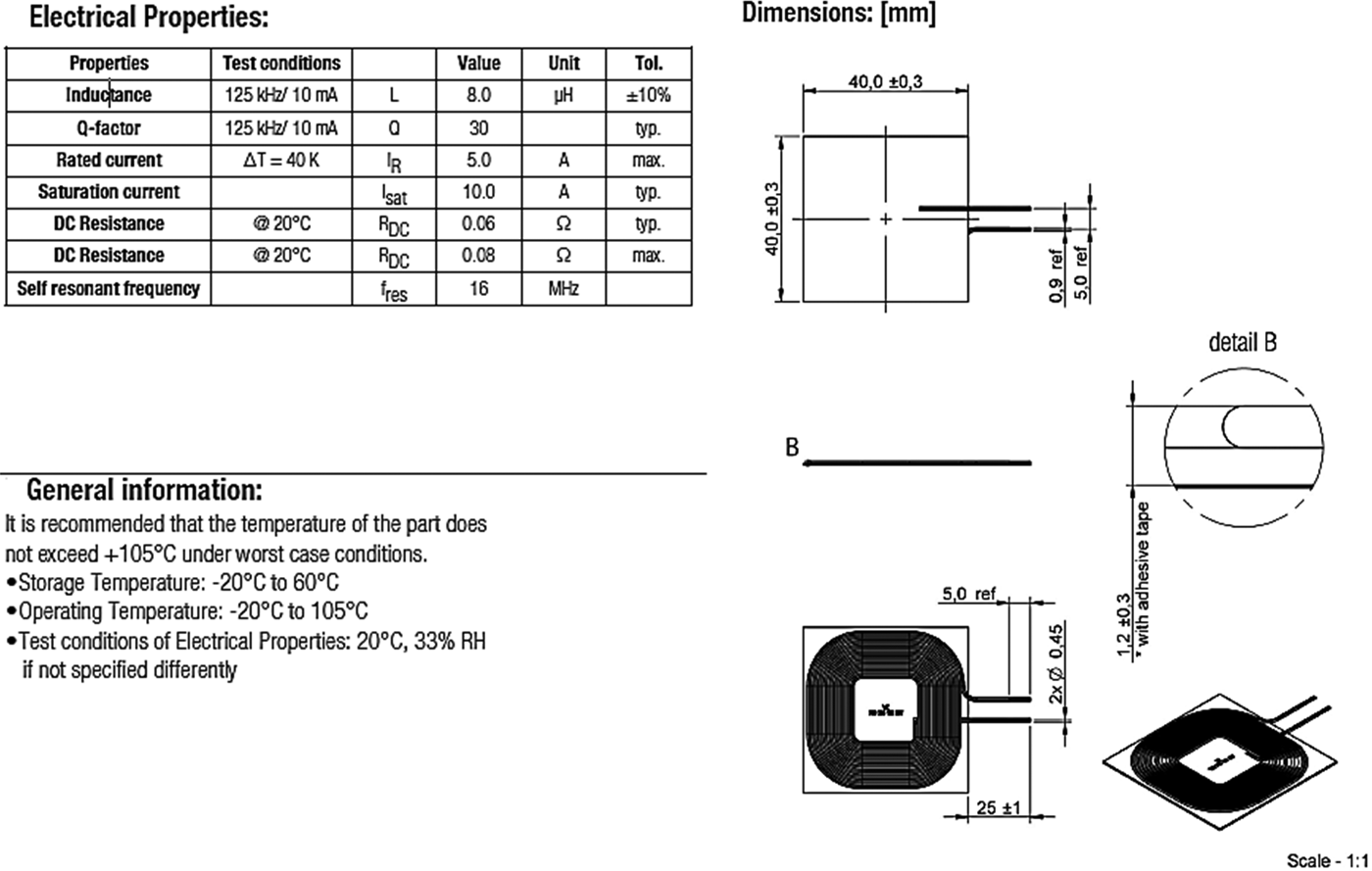
The contacts from the Tx and Rx spirals in the kit were removed from their respective circuit boards for measurements with the VNWA under the same conditions in which all other tests would be completed. This means the same general test set-up in Fig. 6, and with 0 z-distance (separation only by the substrate fabric). A screenshot of this test can be seen in Fig. 9. Reading from the legend on the bottom of the image: The blue line is the parameter S 21 (signal through) in decibels, the red line is parameter S 11 (Tx signal reflection) in decibels, the purple line is mutual inductance in μH, and the black line is the real part of the impedance in ohms. The reference line for each value measurement can be found on the right side of the chart. The scale and unit for each measurement is on the left. The x-axis is the discussed 20–5000 kHz frequency range on the logarithmic scale. The datasheets for each of the Würth Tx and Rx antennas can be found in the Appendix Figs 17 and 18.
Design kit benchmark test in decibels with impedances.

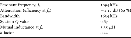
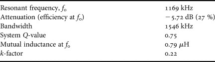
The measurement markers 1, 2, and 3 come from a program function which automatically places them for bandwidth filter design. The marker 1 is that of the resonant frequency, while markers 2 and 3 are the signal attenuation at −3 decibels from that of the attenuation at resonant frequency. Marker 4 is the middle point of the bandwidth and markers 5 and 6 are the two extremes of the frequency range. What can be noted is that the real Z is at a minimum at the device resonant frequency and that the bandwidth of function is wide for the two antennas. Further characteristics drawn from Fig. 9 are listed in Table 4.
Benchmark test reading.

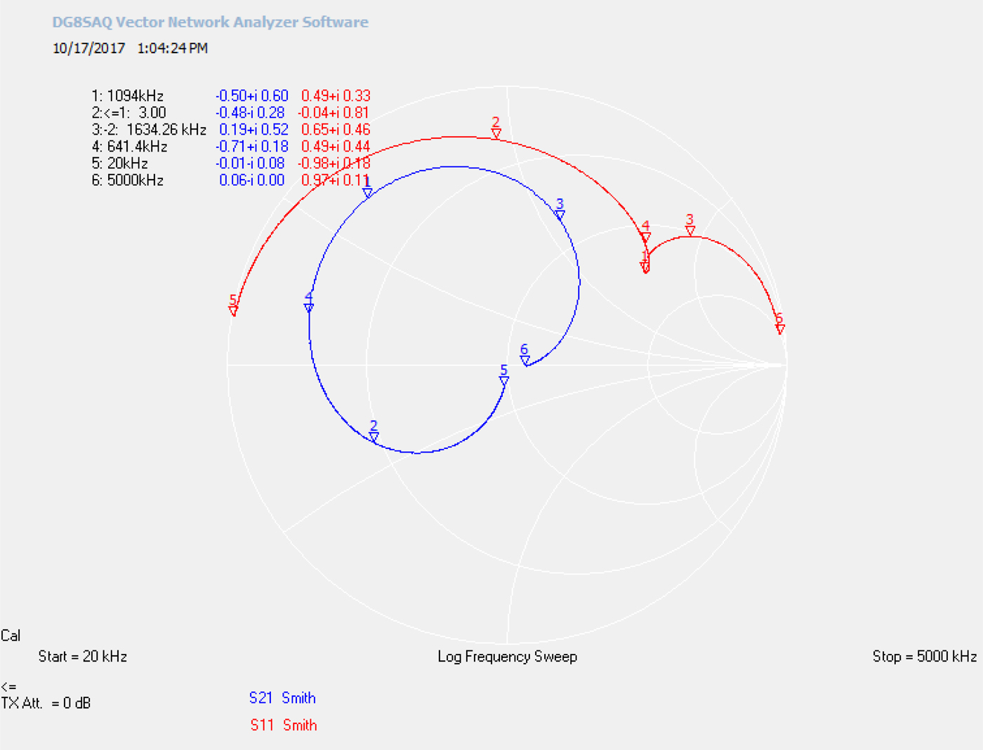
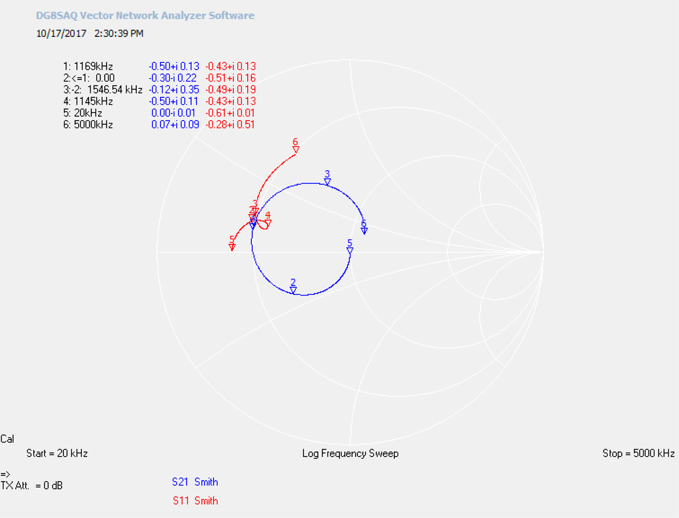
Figure 10 shows the same test as Fig. 9 with the impedance measurements deactivated and the same S 21 and S 11 measurements in the form of a Smith chart with complex readings. The chart shows the performance of this device on the complex plane at different frequency levels. Up until about 640 kHz (marker 4) the system acts as a capacitor until it crosses over into the inductance region for the rest of its functional reading. This can also be used to compare against Fig. 14 and the performance of the produced CFRP-antenna prototype.
Design kit benchmark test in Smith chart.

It should be noted that the benchmark tests measure the resonant frequency and efficiency only of the spirals of the design kit. The device was not in operation during the test and the accompanying circuits for the Tx and Rx spirals most likely influence the actual efficiency and operating frequency of the device. Regardless, these measurements are sufficient for a comparison of functionality of the CRFP-antenna prototypes.
CFRP-antenna prototype:
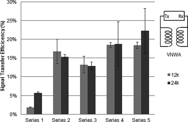
The Rx antenna from the design kit was taken and used as a receiver and measured against the manufactured prototypes as transmitters under the same previous test conditions. This is the same general test set-up in Fig. 6, and with 0 z-distance between the samples (no separation). The results for signal transfer efficiency are given in Fig. 11 at the corresponding resonant frequencies in Fig. 12. All measurements were made within the ranges discussed in the introduction to Section B.
Signal transfer efficiency of composite antenna versions coupled with a standard market receiver.

Resonant frequency of composite antenna versions coupled with a standard market receiver.

A visual inspection of the sample set with the highest deviation, 24k/series 4, proved that there are a significantly higher number of large voids in the resin from trapped air during curing. Other sources of variation could be difficulties in antenna alignment during measurement recording.
V. RESULTS AND DISCUSSION
A) Comparison to benchmark test
In order to best characterize the produced samples, they can be directly compared with the performance of the highest efficiency CFRP antenna with the signal efficiency of the Würth Tx spiral. Both tests performed using the sample Würth Rx spiral as a receiver. Figure 13 is a screenshot of the measurement for a CFRP antenna of 24k carbon roving and series 5 design. The complete results of the signal transfer test, as well as the inductance and resistance tests can be found in Appendix Figs 19 and 20.
Highest efficiency CFRP-antenna measurement in decibels and with impedances for benchmark comparison.

Table 5 shows the readings and calculations from the Fig. 13. This information can be directly compared with the benchmark measurements of Fig. 9 and the readings in Table 4. At first glance it is easy to see that the resonant frequency, Q-value, and k-factor are highly comparable. The biggest differences are that of the mutual inductance and signal transfer efficiency. This is due to the fact that the measured 1.57 µH self-inductance of the chosen CFRP antenna is significantly lower than the 24 µH of the benchmark Tx antenna.
Highest efficiency CFRP antenna measurement readings for benchmark comparison.

Figure 14 shows the same measurements of Fig. 13 with the impedances deactivated and with the S 21 and S 11 parameters in the form of a Smith chart. This visualization of the antenna performance can be directly compared with benchmark measurement Fig. 10. The figures show the same general shape but the CFRP antenna shows a comparative reduction of performance. For example, the signal through measurement shows that the CFRP antenna acts as a capacitor up until 1000 kHz (marker 4) before it settles into its inductive functionality.
Highest efficiency CFRP-antenna measurement in a Smith chart for benchmark comparison.

B) Geometry
The work of Deichselberger et al. [Reference Deichselberger, Bierbaumer, Müller and Horoschenkoff14] was able to achieve relatively higher inductance values for their CFRP antennas, despite a less precise manufacturing process. This reason is heavily based on the antenna geometry. Deichselberger et al. used carbon roving with lower filament content which have a smaller cross-sectional area. They then used spacers which allowed for a close as possible pitch, and more turns in their antenna. These geometric parameters have a greater influence on the inductance and transfer capabilities of the antenna as nuance prototype characteristics.
In the design of the carbon-fiber antennas for this project, the outer diameter was taken to be of higher importance than the inner diameter. After further research and testing, it seems that since the magnetic field flows in a toroidal shape, a larger inner diameter is required for better flow of the magnetic field. This can be seen in Fig. 7 of the self-inductances. Between series 3 and 4 there is an increase in self-inductance due to increasing the number of turns from 5 to 7. Between series 4 and 5 the number of turns increases from 7 to 10, however the increase in self-inductance is less dramatic because the inner diameter minimizes in series 5.
The importance of geometric size is further confirmed by comparing the percentage difference between the two material types. As mentioned earlier, the 12k samples were the same dimensions of the 24k samples, only scaled to 75% of the original size. This means that a 25% increase in conductor diameter, pitch, and diameter contributes to 60–65% increase of the self-inductance of the antennas on this scale.
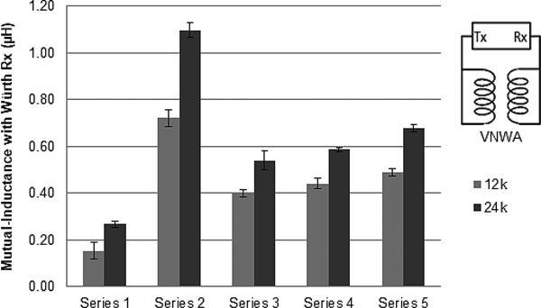
C) Mutual inductance and k-factor
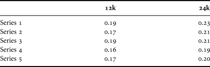
The measurements taken between the prototype Tx and standard Rx antenna also revealed the mutual inductance achieved between the CFRP antennas and the Würth Rx. These results are shown in Fig. 15. The trend across each tested series closely follows that of the self-inductances of each antenna in Fig. 7 only on a lower scale. The mutual inductance measurements were taken at the point of resonant frequency for each signal transfer. However, as seen in Figs 9 and 13, the mutual inductance continues to increase until it peaks shortly after, close to the mid-point between the minimum and maximum real impedance. Using equation (1), the average coupling factor was calculated and is presented in Table 6. The k-factors were expected to be low with low-efficiency readings, but it is interesting to note that they are relatively close to each other in scale.
Average mutual inductance between CFRP antennas and Würth Rx spiral.

Average k-factor across material and series type.

D) Manufacturability of carbon antennas
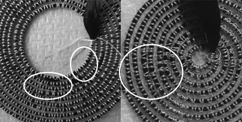
During the start of prototype manufacturing, the machine had to be tuned for the high precision that was required by a combination of parameter settings and attachments to the stitching head. During the production, any samples with severe amounts of missing stitching, loose parts of roving, or significant contact between turns were immediately disqualified as viable prototypes. Minimal amounts of one or a combination of these undesirable effects, shown in Fig. 16, were accepted as viable samples and were considered for testing. The causes were mostly due to improper tensioning between the spool and the head which was regulated and improved during production.
Defects where roving comes out of stitches (left), defect where turns touch (right).

The consistent high-quality and low defects for larger antennas with the longest track indicates the ability of these parts to be in serial production with low defects. In a qualified, serial process, rating criteria with higher resolution can be defined and a full Failure Mode and Effect Analysis (FMEA) can be performed in order to qualify a high yielding process with minimal variability and failures.
IV. OUTLOOK
It should be noted that the measurements from the benchmark test only test the pure signal transfer capabilities of the spirals in the design kit and does not consider the actual operational frequency of the spirals attached to their respective circuits, which is unknown.
Three suggestions can be made in reference to the operational frequency of the CRFP antennas. First, further research can integrate these antennas into live functioning circuits and could pair the inductors with the right compensating capacitor that lowers the resonant frequency. Another suggestion is that, further experimentations in the antenna size can also produce antennas that have naturally lower self-resonant frequencies. Lastly, lowering the operating frequency should typically expand the reception range and higher efficiency can be expected.
There are a number of different brands of carbon roving that are plausible candidates for the technology presented here. First, a more specialized different type of carbon material should be compared with the results of this work to see if they provide a significant improvement to the quantifiable characteristics, as long as they provide cost-benefit. Additionally, appropriate shielding/substrate material can focus the magnetic fields for more focused power transfer. Deichselberger et al. reported that the antenna performance was improved when CFRP was used as a shielding material. This is a positive note as the intended application of the carbon antenna is to integrate them into CFRP components for a multifunctional composite.
V. CONCLUSION
Overall, the results of the tests performed support the goals of this work by proving the feasibility of TFP embroidered carbon-fiber antennas for WPT applications. According to the benchmark comparison between Fig. 9/Table 4 and Fig. 13/Table 5, the presented technology is comparable to its aftermarket counterparts in all important characteristics except for efficiency. The efficiencies of the evaluated antenna inductors were promising enough that they can be integrated into a full circuit and tested further. A highly scalable manufacturing process of these carbon-composite antennas also proved feasible to provide quality, reproducible parts to the market. The primary goal of the research was to test if the presented technology is functional and feasible, and to that end the presented research is considered a success. Further research must be carried out in order to ensure the functionality in a complete circuit, and to determine a standardized design based on a functionality that serves real market needs.
ACKNOWLEDGEMENTS
Thank you to Prof. Breckenfelder and the Hochschule Niederrhein for providing the means and facilities to research this topic. Thank you to Dr. Greb and the Institute of Textile Technology for hosting the thesis work at the RWTH Aachen University. Finally, thank you to project partners Mr. Fabian and Mr. Werner Digel of Digel Sticktech GmbH u. Co. KG for providing the facilities and know-how for the production of the carbon-antenna preforms.
FINANCIAL SUPPORT
This work was supported by the LOGwear Project from Interreg Deutschland Nederland (grant number 144038).
CONFLICT OF INTEREST
None.
ETHICAL STANDARDS
The authors assert that all procedures contributing to this work comply with the ethical standards of the relevant national and institutional committees on human experimentation and with the Helsinki Declaration of 1975, as revised in 2008. The authors assert that all procedures contributing to this work comply with the ethical standards of the relevant national and institutional guides on the care and use of laboratory animals.
ABBREVIATIONS
- AC
alternating current
- CET
contactless energy transfer
- CFRP
carbon-fiber-reinforced plastic
- DC
direct current
- EV
electric vehicles
- EM
electromagnetic
- IPT
inductive power transfer
- RLC
resistance–inductance–capacitance circuit
- Rx
receiver or receiving spiral
- TFP
tailored-fiber-placement
- Tx
transmitter or transmitting spiral
- VNWA
vector network analyzer
- WPT
wireless power transfer
APPENDIX
See Figures 17–20.
Würth Tx spiral data, compliance Qi – A1.

Würth Rx spiral data, Qi compliant.

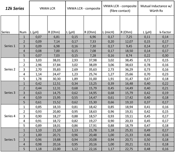
Individual measurements for each of the 25 12k carbon-antenna samples.

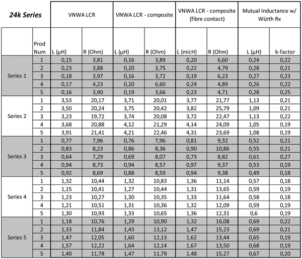
Individual measurements for each of the 25 24k carbon-antenna samples.

 Lucas Anthony Ciccarelli, M.Sc. received a bachelor's degree in mechanical engineering from Philadelphia University in 2013 and received his master's degree in textile engineering from RWTH Aachen University in 2017. Both degrees consisted of focus and research in fiber-reinforced composite materials. He now holds a position as a project and sales engineer for thermoplastic-composites production equipment at AFPT GmbH in Dörth, Germany.
 Prof. Dr.-Ing. Christof Breckenfelder received his Diploma in electrical engineering in 1997 from the Technical University of Berlin and received his Ph.D. at the University of Bremen in 2011. He became a professor for the University of Applied Sciences Niederrhein (Hochschule Niederrhein) in Mönchengladbach, Germany in 2013 for the Faculty of Textile and Clothing Technology with a focus in computer modeling and simulation of textile products.
 Dr.-Ing. Christoph Greb received his Diploma in mechanical engineering in 2008 from RWTH Aachen University and completed his Ph.D. summa cum laude in 2013 also at RWTH Aachen. He is currently the head of the composites division and scientific director for the Institute of Textile Technology in Aachen, Germany.