1. Introduction
Environmental exploration and monitoring have long been among the most prominent applications of autonomous robotic systems [Reference Azouaoui and Chohra1]. The growing environmental problems resulting from human degradation are becoming increasingly evident, justifying the significant increase in the application of robots in different environments, such as oceans [2] and forests [Reference Luiz Fernando Oliveira and Silva3].
Researchers have significantly advanced the quest for practical solutions to environmentally sustainable exploration in unknown areas [Reference Guenat, Purnell, Davies, Nawrath, Stringer, Babu, Balasubramanian, Ballantyne, Bylappa, Chen, Jager, Prete, Nuovo, Ehi-Eromosele, Torbaghan, Evans, Fraundorfer, Haouas, Izunobi, Jauregui-Correa, Kaddouh, Lewycka, MacIntosh, Mady, Maple, Mhiret, Mohammed-Amin, Olawole, Oluseyi, Orfila, Ossola, Pfeifer, Pridmore, Rijal, Rega-Brodsky, Robertson, Rogers, Rougé, Rumaney, Seeletso, Shaqura, Suresh, Sweeting, Buck, Ukwuru, Verbeek, Voss, Wadud, Wang, Winn and Dallimer4, Reference Herbert-Read, Thornton, Amon, Birchenough, Côté, Dias, Godley, Keith, McKinley, Peck, Calado, Defeo, Degraer, Johnston, Kaartokallio, Macreadie, Metaxas, Muthumbi, Obura, Paterson, Piola, Richardson Anthony, Schloss, Snelgrove, Stewart, Thompson, Watson, Worthington, Yasuhara and Sutherland5] and the monitoring of difficult-to-access regions [Reference Paravisi, Santos, Jorge, Heck, Gonçalves and Amory6, Reference Chitikena, Sanfilippo and Ma7], among other pertinent applications. These efforts serve economic, social, and ecological preservation purposes.
Recent solutions include different types of vehicles and navigation environments. It is possible to mention [Reference Zhang, Wang, Tian, Yao and Zhao8] for firefighting missions using a ground robot with a dual-track driving system, [Reference Chang, Hsu, Hung, Ou, Wu and Hsu9] for monitoring water quality using autonomous surface vehicles (ASVs), or [Reference Rejeb, Abdollahi, Rejeb and Treiblmaier10] using drones in agriculture.
Most solutions primarily concentrate on replacing human beings in adverse situations [Reference Jorge, Granada, Maidana, Jurak, Heck, Negreiros, dos Santos, Gonçalves and Amory11], a change that can disrupt the autonomy of the robotic system [Reference Mayya, Ramachandran, Zhou, Senthil, Thakur, Sukhatme and Kumar12], even when considering prospects for redundancy and scalability. This approach is entirely consistent with the motivations behind developing autonomous systems.
Developing solutions for autonomous or semi-autonomous navigation in challenging environments involves significant hurdles. These environments are notably harsh due to natural imperfections and critical functional constraints. Challenges include limited energy resources and the risk of physical damage, which can result in costly equipment losses or, in extreme cases, the loss of human or animal lives.
Realistic simulators are crucial for early-stage experimentation, preventing hardware compromises, saving human resources, and avoiding market recalls due to insufficient guarantees. Therefore, researchers and engineers dedicate much production time to applying simulation/verification tools with increasingly stringent consistency requirements, aiming to discover, in advance, the physical effects in a given application context.
Currently, such solutions typically consider approaches based on the MITL (Model in the Loop) technique, as described in ref. [Reference Plummer13]. This technique employs mathematical models with varying levels of precision. It proves effective for validation in nominal cases, where the stringent requirements of robustness associated with random natural disturbances or equipment construction imperfections are not in play. However, this approach needs to account for the additional effects that computational systems responsible for implementing the solutions may introduce.
Other solutions enable an enhancement of realism by considering the application software and computing platforms that will effectively be employed to implement the practical physical system, exemplified by SITL (Software in the Loop) [Reference Jeong, Kwak and Lee14] and HITL (Hardware in the Loop) [Reference Bacic15]. The former offers efficient methods for functional verification and bug rate minimization, among other advantages, making it imperative in various scenarios, including aquatic [Reference Babic, Vasiljevic and Miskovic16] and aerial [Reference Silano, Oppido and Iannelli17] environments. Researchers increasingly apply the second solution to achieve total realism in simulations. This approach allows accurate temporal verification and validation of energetic and computational aspects for elements incorporated into the actual application [Reference Xian, Zhao, Zhang and Zhang18–Reference Mihalic, Truntic and Hren20]. The success of implementing these techniques added to new methodologies for simulation such as HuITL (Human-in-the-Loop) [Reference Ton, Kan and Mehta21, Reference de Mello, Jimenez, Ribeiro, Guimarães and Frizera-Neto22], RITL (Render-in-the-Loop) [Reference Ivanovic, Polic, Tabak and Orsag23], and SyITL (System-in-the-Loop) [Reference Brandl, Montoya, Strauss-Mincu and Calin24], among others in the sense of greater generalization, allow the adoption of more appropriate terminologies such as those called CITL (Component-in-the-loop) [Reference Fagcang, Stobart and Steffen25] or even XITL (X-in-the-loop) [Reference Moten, Celiberti, Grottoli, van der Heide and Lemmens26].
Among the applications that justify the existence of this diversity of simulation techniques, monitoring in aquatic environments stands out. In this case, there are several challenging scenarios, making it the target of pioneering investigations worldwide, such as autonomous monitoring of earthquakes and tsunamis [Reference Sathiakumar27] or deep-water exploration [Reference Laschi and Calisti28].
This article proposes a new architecture for designing a realistic simulation system that includes the simulation technologies mentioned above, based on consolidated open-source tools and general knowledge of the scientific communities and developers of autonomous robotic systems. Specifically, this article has the following main contributions:
-
• Agnostic to a specific computational resource, which allows bringing together aspects such as supporting the direct integration of multiple commercial or customized vehicles simultaneously with the dynamic inclusion of widespread environmental imperfections and natural objects;
-
• Generalized integration, producing effective technical support for MITL, SITL, and HITL techniques, among other state-of-the-art trends in realistic simulation;
-
• Scalable, regardless of the number of autonomous agents or elements in the simulation scenario;
-
• Flexible, being able to work with several different hardware and software configurations in order to bring simulation closer to reality;
-
• Advanced responsiveness can be achieved by including redundant elements in specific architectural items.
Gazebo and ArduPilot software, alongside the Robot Operating System (ROS) framework, address these requirements. Additionally, we specify efficient integration solutions, allowing for preliminary validations across various design aspects of embedded autonomous systems. This proposal aims to fill the existing gap of simulation systems capable of integrating hardware and software for the hierarchical processing of on-board autonomous navigation strategies. Attractive solutions such as the [Reference Bujas, Dworak, Turek and Byrski29] proposal are aimed at nonrealistic simulations, supported by a high-performance computing framework. In this case, the proposal does not consider the practical aspects inherent to embedded systems, which limits its applicability in different application scenarios.
To the best of these authors’ knowledge, there is no single and effective solution capable of covering all verification and validation requirements for solutions for design autonomous vessels and intelligent monitoring systems. The various open-source tools available, when used individually, even considering the existence of aggregating initiatives in the form of competitions such as the Virtual RobotX (VRX) [Reference Bingham, Agüero, McCarrin, Klamo, Malia, Allen, Lum, Rawson and Waqar30] simulation and various open repositories from equipment manufacturers, do not meet the requirements for validation customarily required. Furthermore, even with the inherently distributed philosophy typical of contemporary software solutions, there needs to be a formal methodology to bring together these tools that meet all related development demands.
This article validates the proposed architecture through a practical application that addresses the navigation challenges in the rivers of the Brazilian Amazon region. These challenges are integral to a global context with a strong emphasis on environmental and social sustainability. The ASV navigation missions involve operations along the Madeira River between the states of Rondônia and Amazonas. This river spans 3,315 km in length, ranking as the 17th largest in the world. Its geographical configuration naturally tests the operational limits of any monitoring system.
In this context, we specifically focus on the Santo Antônio hydroelectric plant facilities. These installations can highlight the importance of monitoring tasks for heterogeneous impurities to prevent environmental disasters or interrupt generating units. Such disturbances directly and significantly impact the Brazilian integrated generation system due to destructive interactions between natural elements, random objects (such as animals, trunks, branches, and vegetation), and buildings. In this specific scenario, the use of simulators becomes especially critical.
The proposed solution has the necessary generality to be extended to several other application scenarios or types of autonomous vehicles. Its modular structure allows the replacement of specific elements without compromising the original integrative capacity. The results indicate the proposal’s feasibility, and a more in-depth discussion of the real-world results provides a more detailed assessment.
The remaining sections of the text are structured as follows: in Section 2, we outline the primary problems identified in the case study, facilitating the collection of requirements for the proposed architecture. Section 3 provides a comprehensive description of the proposed solution. In Section 4, we present some of the achieved results. Finally, in Section 5, we offer concluding remarks and discuss expectations for future work.
2. Problem statement
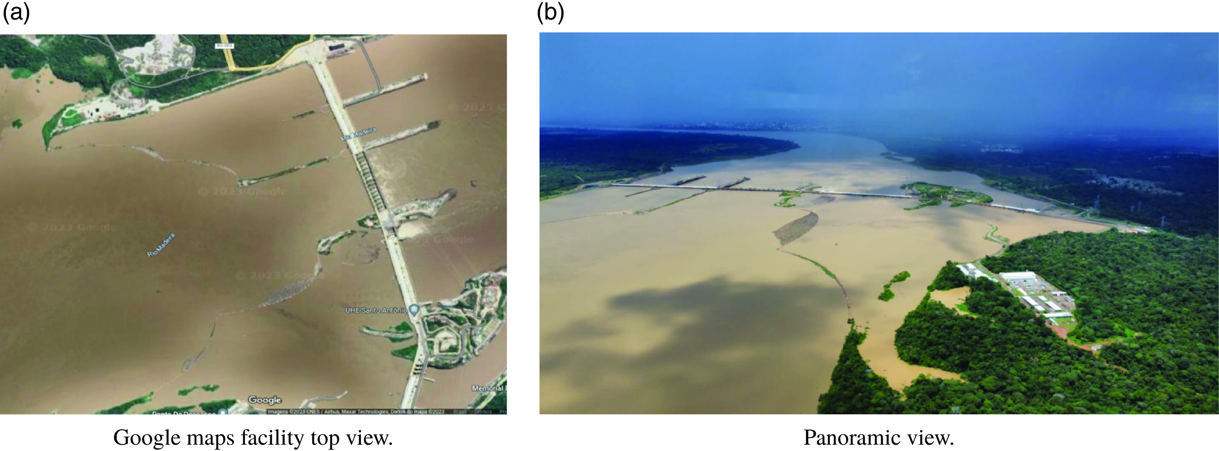
In justifying the scientific effort in designing a new integrated architecture for realistic simulation, one must consider the specific characteristics of a relevant application scenario that highlights the challenges of designing ASVs and navigation algorithms for adverse environmental conditions. As previously stated, the solutions proposed in this article are validated in a practical context related to autonomous navigation on the Madeira River in Rondônia-Brazil at the Santo Antônio hydroelectric plant facilities. Figure 1a shows a satellite image of the regions of interest, and Figure 1b shows a panoramic view.
Views of Santo Antônio hydroelectric power plant facilities (https://goo.gl/maps/Q7n5RZpm7e2futZD7).

Such images, in a macro-level observation, show two initial challenges, highlighted below:
-
• Navigation zone with large dimensions: In this case, it is not feasible to use conventional navigation strategies that do not foresee the optimization of energy resources and effective coverage area. Additionally, computational models, especially those related to graphical rendering, must be optimized.
-
• Water turbidity: The natural condition of the navigation surface makes it difficult or even impossible to use conventional cameras, LiDAR, and even human operations for monitoring and moving traction vessels.
To further highlight this last issue, the point cloud produced by a Livox MID-70 LiDAR was acquired in two different environments, as illustrated in Figures 2a and 2b. It is possible to notice that the waters of the Madeira River reflect LiDAR rays as if they were a solid plane in an invisible region below the surface.
In this scenario, it is necessary to have a multisensory system composed of LiDAR and Sonar for the complete mapping of solid structures above and below the water level, directly implicating the onboard computational and energy requirements.
From the point of view of realistic simulation systems, this problem still needs to be solved when considering the large volume of data, synchronization demands, and sophistication of modern algorithms for processing point clouds, making adopting centralized structures unfeasible.
At a localized level, the Log Boom safety mechanism retains impurities in the river, protecting the dam and ensuring proper disposal to maintain the ecosystem balance [Reference Katsuno, de Castro and Dantas31]. Figure 2c shows a Log Boom full of impurities, and Figure 2d illustrates their removal by human intervention.
Issues associated with data acquisition and the accumulation of impurities.

As can be seen, they are heterogeneous sediment made up of materials of different sizes that, when associated with local biodiversity, make direct human interventions unfeasible, requiring heavy machinery. This reality implies more operational costs, problems with logistical optimization for allocating personnel and equipment, and risks of disruption of the Log Boom, among other potential problems.
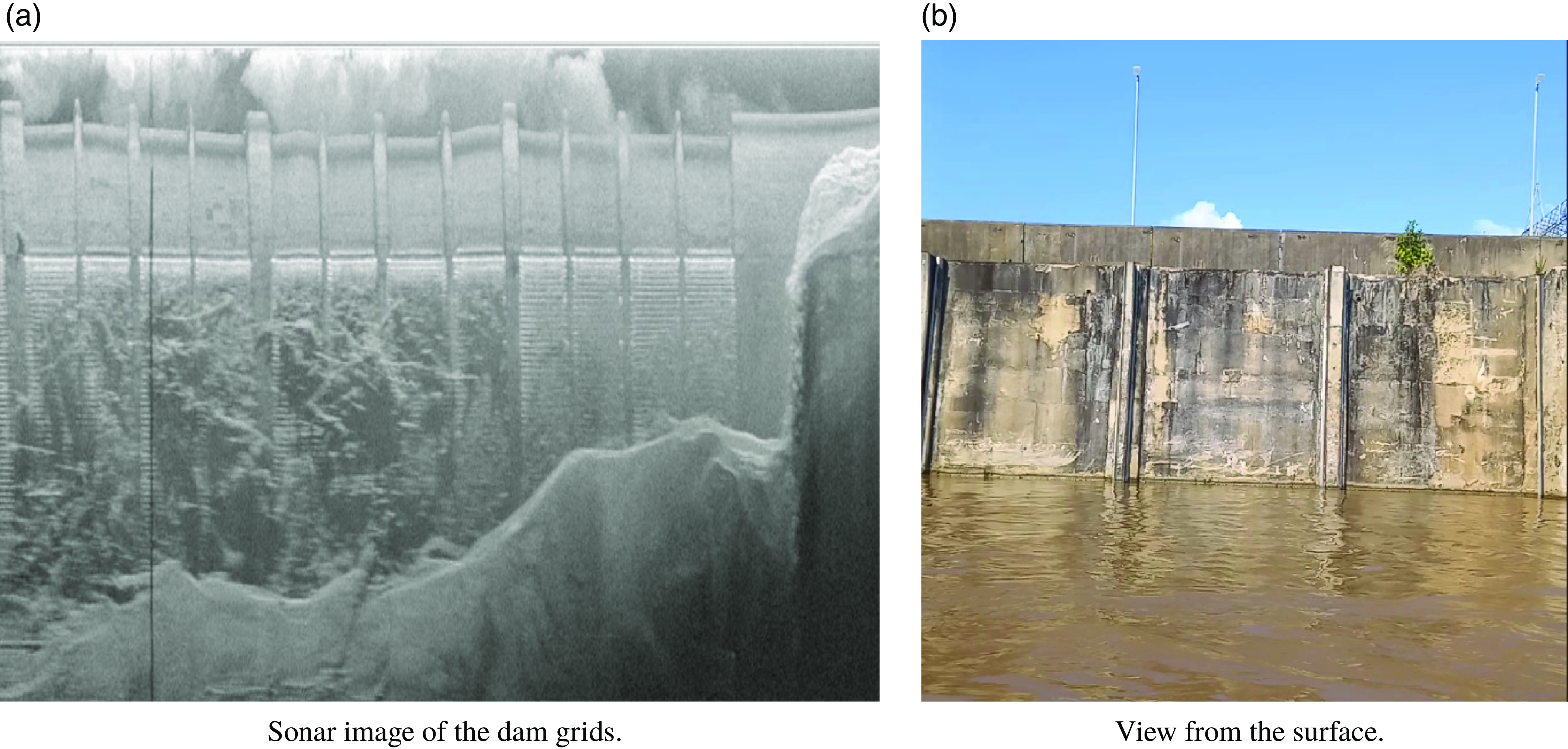
In case of Log Boom failure, a large volume of high-density waste may pass to the area in front of the dam, severely compromising the plant operation and producing consequences in the most varied regulatory instances of the plant operation. Figure 3a shows a multibeam sonar image illustrating the accumulation of woody and sedimentary material in the adduction zone, close to the dam grids, making it possible to attest to the application’s severity and, as expected, nothing can be seen from the surface (Figure 3b).
Submerged impurities accumulated in the dam grids.

As can be seen, the amount of material accumulated in front of the grids considerably compromises the flow of water to the internal structures of the dam, which affects the production of a given generating unit, in addition to the risk of rupture of the protection grids that would lead to the damage on even larger scales.
Additionally, random wind gusts impacting specific objects, high-magnitude localized water currents, vortices, fog, and others can cause serious accidents. These issues can lead to operational instability and severe consequences for the surrounding community without costly financial measures.
The objects accumulated in the grid were transported by the current of the river, which has an irregular riverbed with considerably shallow sections, which further increases the challenges associated with navigation tasks. This reality justifies the adoption of air-propelled ASVs, capable of moving on the surface and carrying sensors to implement mapping and obstacle avoidance algorithms.
These particularities prevent the adoption of monolithic solutions composed only of a flight control unit or a computational structure. The above features highlight the need for high onboard computing power to implement sophisticated navigation algorithms not found in currently available autopilot systems. On the other hand, one needs more than a single processing node because when solving the software implementation problem, the hardware specifications will be a bottleneck, potentially harming the real-time requirements. Added to this is the unavailability of realistic simulation systems that combine the two previous scenarios.
Designing an embedded solution that satisfies all the requirements presented without the minimum security and performance guarantees is unfeasible. In this sense, a novel solution is proposed for simulating monitoring missions capable of supporting decisions by field teams in the more diverse aspects. Additionally, the new integrated architecture supports advanced simulation strategies. It validates the main requirements for semi-automatic inspection systems, optimizes human and machine resources, and enables new projects for monitoring systems, including automatic intervention in areas of interest.
3. Proposed architecture
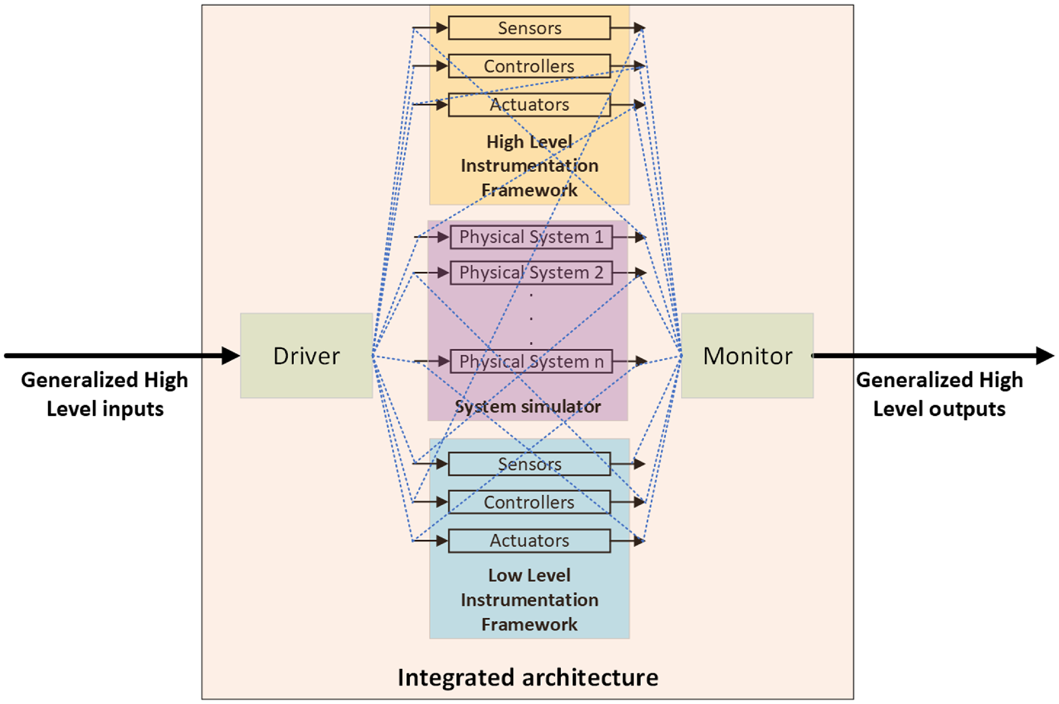
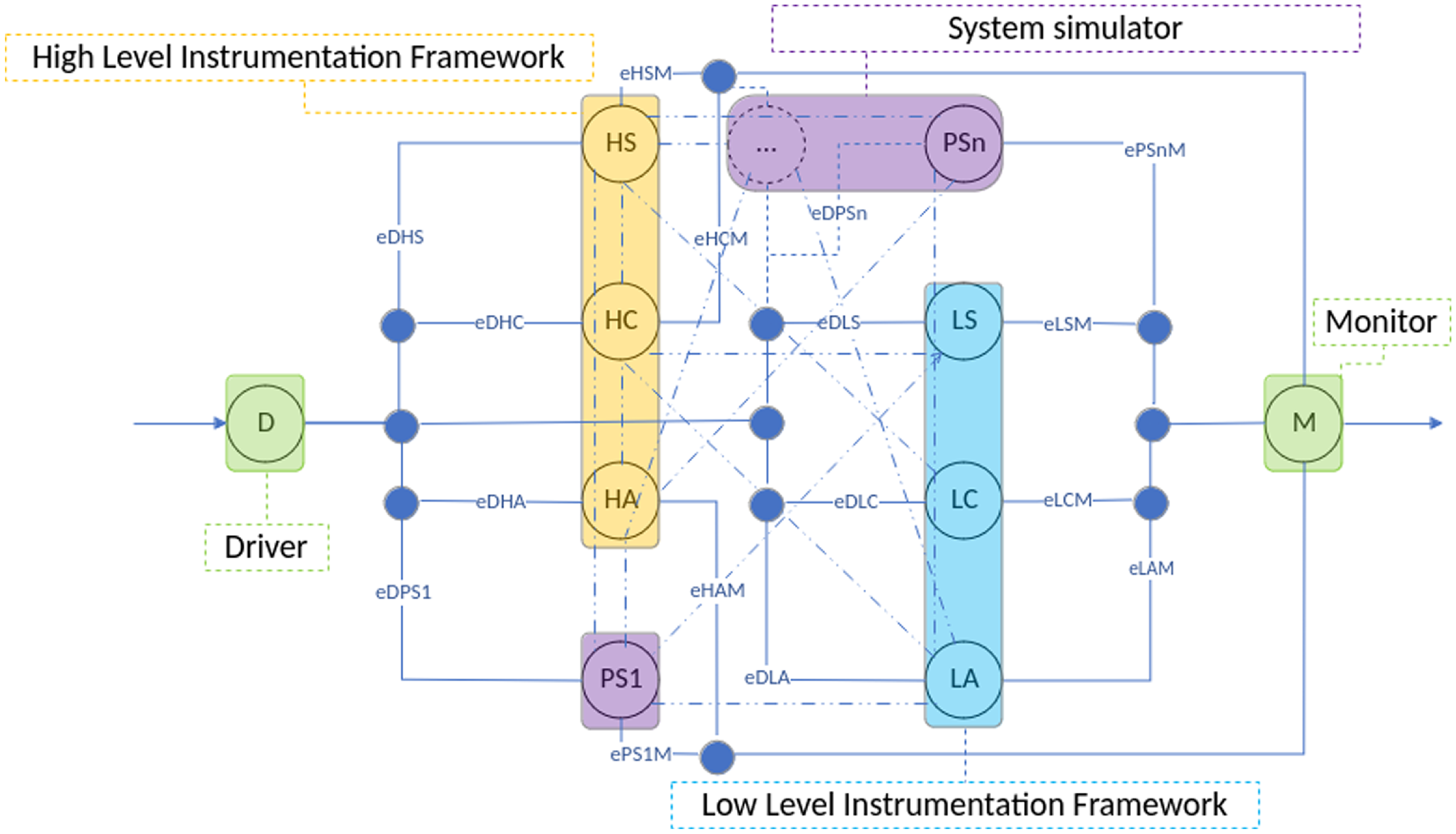
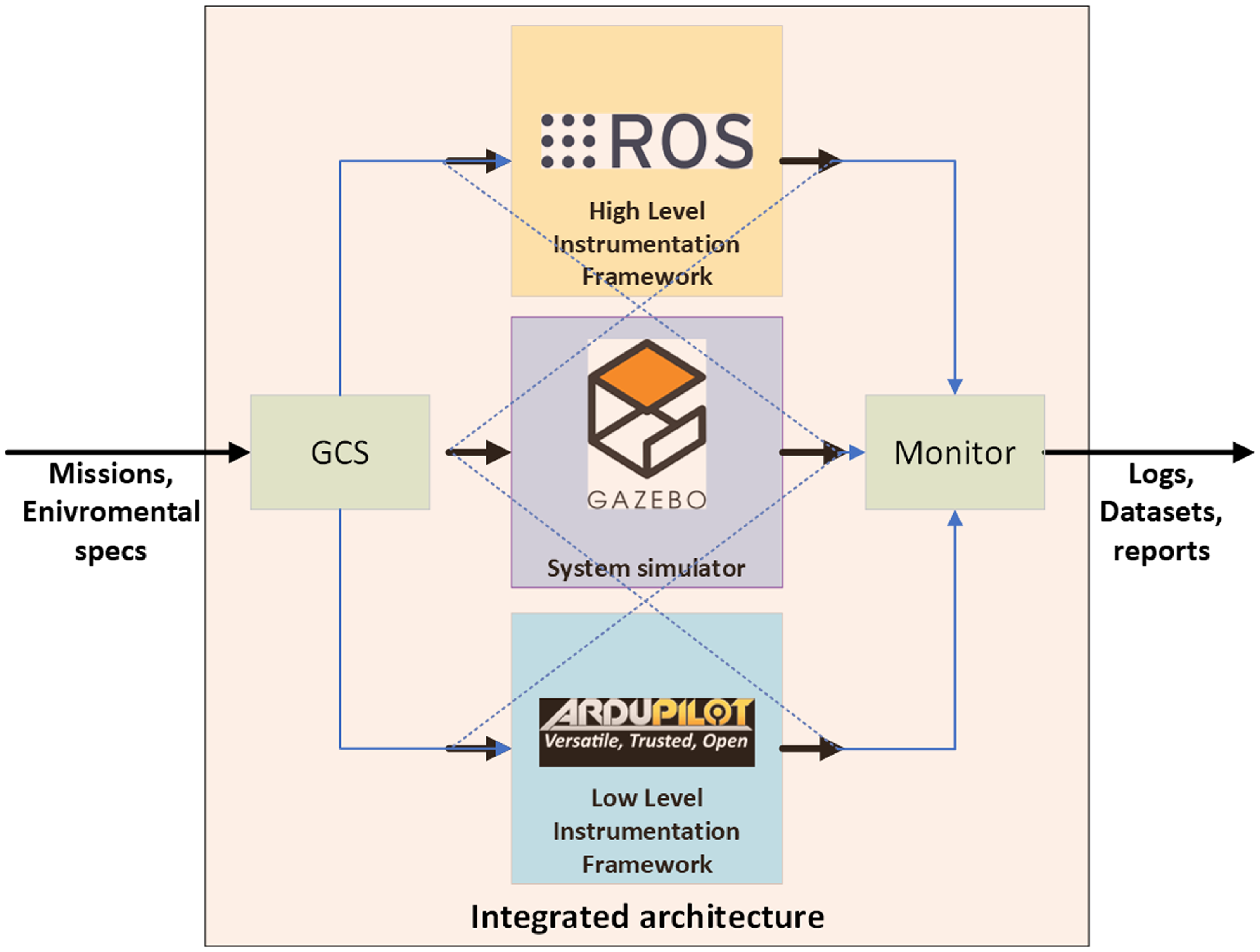
A careful selection of consolidated tools is mandatory to provide the required conceptual, functional, and temporal verification requirements in the context of the target application. These tools should be capable of forming a cohesive entity at a high level, enabling effective evaluations of the efficiency and effectiveness of the solutions across all presented domains. In the following sections, we propose a generalist solution composed of at least five main elements, as illustrated in Figure 4. Following is a general overview of these elements:
Generic view of the proposed architecture.

-
• Driver: Functioning as a multilevel converter, it receives data at the transaction level and converts it to the signal level for subsequent elements. Such signals can be physical or logical stimuli and are provided by specific processing node
 $D$
.
-
• System simulator: A 3D simulator equipped with an efficient physics engine and naturally distributed implementation, capable of meeting the interprocess communication requirements required for integration with other processing nodes, whether physically distributed or not. It is composed of processing nodes
$PS1$
,
$PS2$
, …,
$PSn$
, members of a supernode
$S$
. -
• A set of low-level tools: Consolidated solutions for instrumentation through strategies of low computational complexity, enabling complete operational security of associated robotic systems and equipped with computational facilities for integration. It is composed of processing nodes
$LS$
,
$LC$
,
$LA$
, members of a supernode
$L$
. -
• A set of high-level tools: Consolidated solutions for robotics instrumentation through strategies of high computational complexity, capable of extending the solution’s range of applications and endowed with computational facilities for integration. It is composed of processing nodes
$HS$
,
$HC$
,
$HA$
, members of a supernode
$H$
. -
• Monitor: As opposed to the driver, it converts data at the level of signals originating from the physical or logical elements of the architecture to data at the transaction level that produces high-level outputs for real or virtual users. It is composed of processing output node
$M$
.


The proposed integrated architecture can be better formalized through a undirected graph, as illustrated in Figure 5.
Graph generic representation of proposed architecture. For simplicity of representation, the intermediate edges are not labeled.

Formally, let
 $ \mathcal{G} = (\mathcal{N}, \mathcal{E}, W)$
be a graph where:
-
•
$ \mathcal{N}$
is the set of nodes and supernodes:(1)
\begin{align} \mathcal{N} = \{D, S, L, H, M\}. \end{align}
-
•
$ \mathcal{E}$
is the set of edges. Each edge, denoted as
$ e_{xy}$
, is defined for every ordered pair
$ (x, y)$
where
$ x$
and
$ y$
are elements of
$ \mathcal{N}$
, representing a connection from
$ x$
to
$ y$
:(2)
\begin{align} \mathcal{E} = \{e_{xy} \mid (x, y) \in \mathcal{N} \times \mathcal{N}\}. \end{align}
-
• The adjacency matrix
$ A$
is defined as a
$ \left |\mathcal{N}\right | \times \left |\mathcal{N}\right |$
matrix where each element
$ a_{ij}$
is given by:(3)
\begin{align} a_{ij} = \begin{cases} 1 & \text{if } e_{ij} \in \mathcal{E};\\ 0 & \text{otherwise}. \end{cases} \end{align}
-
•
$ W$
is the weight vector representing the weights of the vertices, where each vertex
$ x \in \mathcal{N}$
has an associated weight
$ w_x$
, representing the weight of vertex
$ x$
, determined by the available physical resource:(4)
\begin{align} W = \{w_D, w_S, w_L, w_H, w_M\}. \end{align}


Generally, we have the following representation:
 \begin{align} A = \begin{bmatrix} e_{DD_{1 \times 1}} & e_{DS_{1 \times n}} & e_{DL_{1 \times 3}} & e_{DH_{1 \times 3}} & e_{DM_{1 \times 1}} \\[3pt] e_{SD_{n \times 1}} & e_{SS_{n \times n}} & e_{SL_{n \times 3}} & e_{SH_{n \times 3}} & e_{SM_{n \times 1}} \\[3pt] e_{LD_{3 \times 1}} & e_{LS_{3 \times n}} & e_{LL_{3 \times 3}} & e_{LH_{3 \times 3}} & e_{LM_{3 \times 1}} \\[3pt] e_{HD_{3 \times 1}} & e_{HS_{3 \times 1}} & e_{HL_{3 \times 3}} & e_{HH_{3 \times 3}} & e_{HM_{3 \times 1}} \\[3pt] e_{MD_{1 \times 1}} & e_{MS_{1 \times n}} & e_{ML_{1 \times 3}} & e_{MH_{1 \times 3}} & e_{MM_{1 \times 1}} \\[3pt] \end{bmatrix}, \end{align}
with:
 \begin{align} e_{DD} = e_{DM} = e_{MD} = e_{MM};\end{align}
 \begin{align} e_{SS} & = \begin{bmatrix} e_{PS1PS1} & \ldots & e_{PS1PSn} \\[5pt] \vdots & \ddots & \vdots \\[5pt] e_{PSnPS1} & \ldots & e_{PSnPSn} \end{bmatrix}; \end{align}
 \begin{align} e_{LL} &= \begin{bmatrix} e_{LSLS} & e_{LSLC} & e_{LSLA} \\[5pt] e_{LCLS} & e_{LCLC} & e_{LCLA} \\[5pt] e_{LALS} & e_{LALC} & e_{LALA} \\[5pt] \end{bmatrix}; \end{align}
 \begin{align} e_{SD} &= \begin{bmatrix} e_{PS1D} & e_{PS2D} & \dots & e_{PSnD} \end{bmatrix}^{T}; \end{align}
 \begin{align} e_{DL} &= \begin{bmatrix} e_{DLS} & e_{DLC} & e_{DLA} \end{bmatrix};\end{align}
 \begin{align} e_{DH} &= \begin{bmatrix} e_{DHS} & e_{DHC} & e_{DHA} \end{bmatrix}; \end{align}
 \begin{align} e_{HH} &= \begin{bmatrix} e_{HSHS} & e_{HSHC} & e_{HSHA} \\[5pt] e_{HCHS} & e_{HCHC} & e_{HCHA} \\[5pt] e_{HAHS} & e_{HAHC} & e_{HAHA} \\[5pt] \end{bmatrix}; \end{align}
 \begin{align} e_{SL} &= \begin{bmatrix} e_{PS1LS} & e_{PS1LC} & e_{PS1LA} \\[5pt] e_{PS2LS} & e_{PS2LC} & e_{PS2LA} \\[5pt] \vdots & \vdots & \vdots \\[5pt] e_{PSnLS} & e_{PSnLC} & e_{PSnLA} \\[5pt] \end{bmatrix}; \end{align}
 \begin{align} e_{SH} &= \begin{bmatrix} e_{PS1HS} & e_{PS1HC} & e_{PS1HA} \\[5pt] e_{PS2HS} & e_{PS2HC} & e_{PS2HA} \\[5pt] \vdots & \vdots & \vdots \\[5pt] e_{PSnHS} & e_{PSnHC} & e_{PSnHA} \\[5pt] \end{bmatrix}; \end{align}
 \begin{align} e_{SM} &= \begin{bmatrix} e_{PS1M} & e_{PS2M} & \dots & e_{PSnM} \end{bmatrix}^{T}; \end{align}
 \begin{align} e_{LS} &= \begin{bmatrix} e_{LSPS1} & e_{LCPS1} & e_{LAPS1} \\[5pt] e_{LSPS2} & e_{LCPS2} & e_{LAPS2} \\[5pt] \vdots & \vdots & \vdots \\[5pt] e_{LSPSn} & e_{LCPSn} & e_{LAPSn} \\[5pt] \end{bmatrix}^{T}; \end{align}
 \begin{align} e_{LH} &= \begin{bmatrix} e_{LSHS} & e_{LSHC} & e_{LSHA} \\[5pt] e_{LCHS} & e_{LCHC} & e_{LCHA} \\[5pt] e_{LAHS} & e_{LAHC} & e_{LAHA} \\[5pt] \end{bmatrix}; \end{align}
 \begin{align} e_{LM} &= \begin{bmatrix} e_{LSM} & e_{LCM} & e_{LAM} \end{bmatrix}^{T}; \end{align}
 \begin{align} e_{HS} &= \begin{bmatrix} e_{HSPS1} & e_{HCPS1} & e_{HAPS1} \\[5pt] e_{HSPS2} & e_{HCPS2} & e_{HAPS2} \\[5pt] \vdots & \vdots & \vdots \\[5pt] e_{HSPSn} & e_{HCPSn} & e_{HAPSn} \\[5pt] \end{bmatrix}; \end{align}
 \begin{align} e_{HL} &= \begin{bmatrix} e_{HSLS} & e_{HSLC} & e_{HSLA} \\[5pt] e_{HCLS} & e_{HCLC} & e_{HCLA} \\[5pt] e_{HALS} & e_{HALC} & e_{HALA} \\[5pt] \end{bmatrix}; \end{align}
 \begin{align} e_{HM} &= \begin{bmatrix} e_{HSM} & e_{HCM} & e_{HAM}\end{bmatrix}^{T}. \end{align}
Note that, as this is an undirected graph,
 $a_{ij} = a_{ji}$
for all
 $ i \neq j$
. In a practical sense, many edges will be inexistent depending on the computational tools chosen and specific interconnections. To evaluate the degree of realism of the simulations about a given experimental setup, we present the following metrics:
-
• Weighted Average Degree: Adaptation of the average degree concept to consider the physical characteristics of the processing node that implements a given resource. It is given as follows:
(22)where:
\begin{align} \overline{d}_w = \frac{\sum _{i=1}^n w_i (d_i - 1)}{n} \end{align}
-
–
$n = |\mathcal{N}|$
is the number of vertices of
$\mathcal{G}$
. -
–
$w_i \in \mathbb{R}^+$
is the weight of vertex
$v_i \in \mathcal{N}$
. -
–
$d_i = \sum _{j=1}^n a_{ij}$
is the degree of vertex
$v_i$
.
-
-
• Weighted Degree Realism Index (WDRI): Index for measuring the degree of realism of simulations. It is stated as follows:
(23)where
\begin{align} \text{WDRI} = 1 - \left | \frac{\overline{d}_{w,\text{sim}} - \overline{d}_{w,\text{ref}}}{\overline{d}_{w,\text{ref}}} \right | \end{align}
$\overline{d}_{w,\text{sim}}$
is the weighted average degree of the actual simulation graph and
$\overline{d}_{w,\text{ref}}$
is the weighted average degree of a reference application graph.


The value of WDRI ranges from 0 to 1, where:
-
•
$\text{WDRI} = 1$
indicates a perfect match between the simulated and reference graphs. -
•
$\text{WDRI} = 0$
indicates the maximum discrepancy between the simulated and reference graphs.


For a case of complete interconnectivity and without weighting at the vertices, we have
 $\overline{d}_w,\text{real} = 8.0$
, which is the average degree of a complete graph with n vertices.
With this representation, we establish a formal mathematical object with consolidated tools to guide the main aspects of hardware and software, including in an applied high-performance computing context, essential for effective, realistic simulations and safe, practical implementations.
This proposal is application-agnostic and adaptable to various scenarios through modifications in hardware and software. This article consolidates solutions for designing autonomous robotic systems, aiming for complete integration. Our goal is to develop an architecture that meets specifications with minimal effort and technical training for operators. The specified modules are shown in Figure 6.
Overiview of the proposed simulation system.

The justifications for specifying each of the individual modules are given as follows:
-
• Gazebo [Reference Koenig and Howard32]: A solution for the 3D simulation of robotic systems already quite consolidated. Several plugins for sensors, actuators, hierarchical controllers, and heterogeneous environments (terrestrial, aquatic, and aerial) are available in open source for the academic and developer communities. Its fully distributed nature and implementation in C++ enables efficient integration with the many other elements, which are naturally supported.
-
• ArduPilot [33]: Consolidated FCU software has a framework of reliable solutions for developing autopilots for diversified vehicles. It also has an implementation in C++, making it very attractive for developing low-level and embedded solutions, including support for elementary instrumentation and many typical devices, facilitating the portability work for real applications.
-
• ROS [Reference Quigley, Conley, Gerkey, Faust, Foote, Leibs, Wheeler and Ng34]: A multilingual framework considered a de facto standard for developing robotic systems. It also has a distributed implementation and a wide range of high-level navigation solutions, including SLAM techniques, trajectory planning and control, and compatibility with libraries such as OpenCV and PCL, among other benefits that make it the ideal solution for this essential element of this proposal.
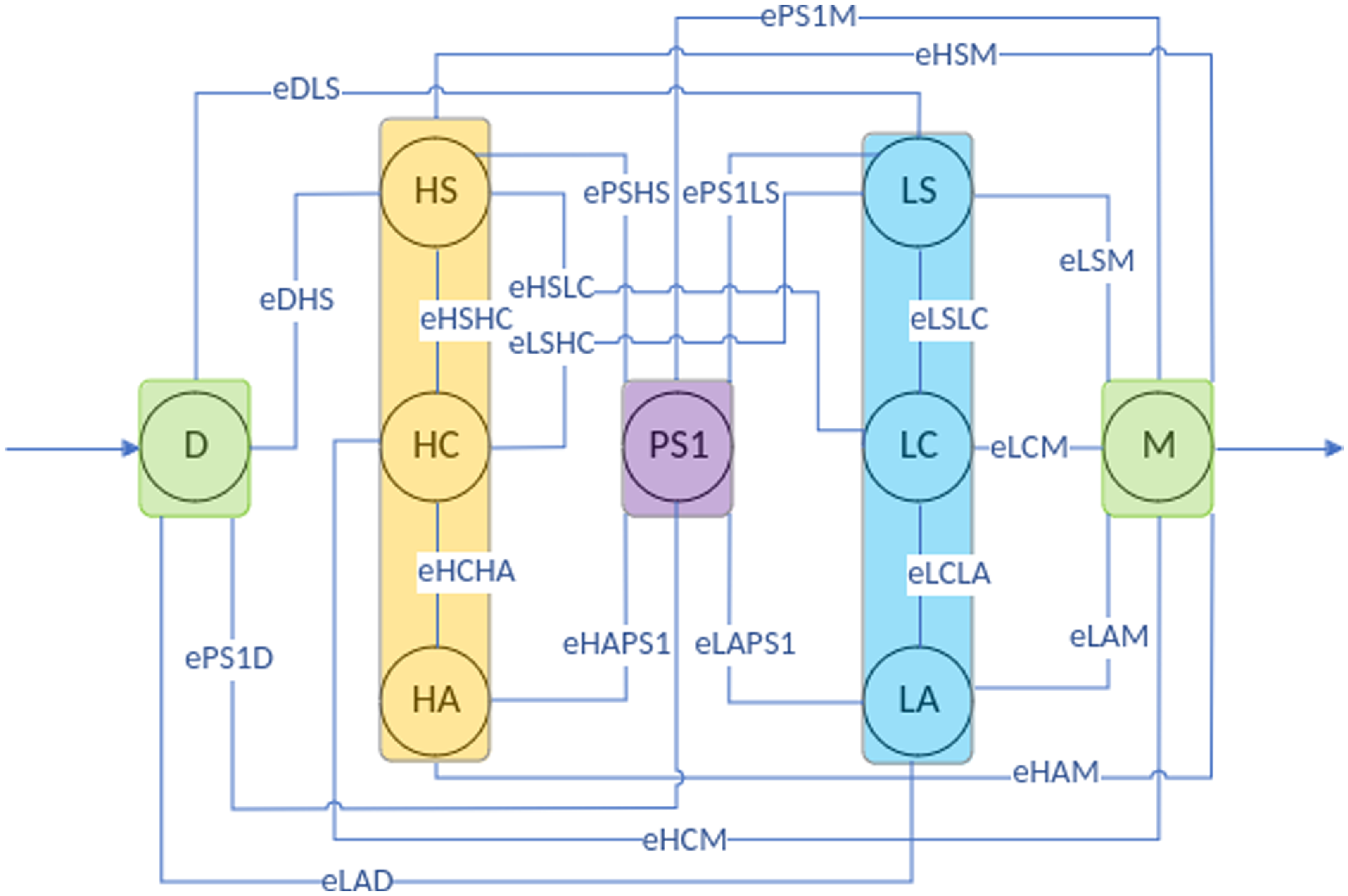
The distributed nature of these tools makes the integration process more straightforward. Figure. 7 shows the specific graph representation for this set of tools.
Graph-specific representation of proposed architecture.

For this representation and considering a general usage of specified tools, we have the following adjacency matrix:
 \begin{align} A = \begin{bmatrix} 0 & 1 & 1 & 1 & 1 & 1 & 1 & 0 & 0 \\[5pt] 1 & 0 & 1 & 1 & 1 & 1 & 0 & 1 & 1 \\[5pt] 1 & 1 & 0 & 1 & 0 & 0 & 1 & 0 & 1 \\[5pt] 1 & 1 & 1 & 0 & 1 & 1 & 0 & 0 & 1 \\[5pt] 1 & 1 & 0 & 1 & 0 & 0 & 0 & 0 & 1 \\[5pt] 1 & 1 & 0 & 1 & 0 & 0 & 1 & 0 & 1 \\[5pt] 1 & 0 & 1 & 0 & 0 & 1 & 0 & 1 & 1 \\[5pt] 0 & 1 & 0 & 0 & 0 & 0 & 1 & 0 & 1 \\[5pt] 0 & 1 & 1 & 1 & 1 & 1 & 1 & 1 & 0 \\[5pt] \end{bmatrix}. \end{align}
In this case, the weight vector is given by:
 \begin{align} W = \{ 1, 0.5, 1.0, 1.0, 1.0, 1.0, 1.0, 1.0, 1.0 \}. \end{align}
In this case, we have
 $\overline{d}_w,\text{sim}=4$
, resulting in a WDRI of 0.5. We use this WDRI value as a weighting factor for the vertices, aiming to reflect this quantity in the evaluations. Specifically, the weight
 $ w_x$
is set to 1 for real and 0.5 for virtual resources.
As a simple example, let us consider a simple SITL approach:
-
• Only one simulator exists, implying there are no other simulators
$ PS_{i}$
in set
$ S$
for any
$ i \neq 1$
:
$ \exists PS_1 \in S \quad \text{and} \quad \forall i \neq 1, \, \nexists PS_i \in S$
. -
• No high-level resources, implying there are neither
$ HC$
nor
$ HC$
nor
$ HA$
in set
$ H$
:
$\nexists HS \in H \text{and}\ \nexists HC \in H\ \text{and}\ \nexists HA \in H$
. -
• Neither Driver nor Monitor:
$ \nexists D \in \mathcal{N} \quad \text{and} \quad \nexists M \in \mathcal{N}$
; -
•
$\overline{d}_w,\text{ref} = 4$
-
• W =
$\{ 0, 0.5, 0.5, 0.5, 0.5, 0, 0, 0, 0 \}$









In this case, we have the following adjacency matrix:
 \begin{align} A = \begin{bmatrix} 0 & 0 & 0 & 0 & 0 & 0 & 0 & 0 & 0 \\[5pt] 0 & 0 & 1 & 1 & 1 & 0 & 0 & 0 & 0 \\[5pt] 0 & 1 & 0 & 1 & 1 & 0 & 0 & 0 & 0 \\[5pt] 0 & 1 & 1 & 0 & 1 & 0 & 0 & 0 & 0 \\[5pt] 0 & 1 & 1 & 1 & 0 & 0 & 0 & 0 & 0 \\[5pt] 0 & 0 & 0 & 0 & 0 & 0 & 0 & 0 & 0 \\[5pt] 0 & 0 & 0 & 0 & 0 & 0 & 0 & 0 & 0 \\[5pt] 0 & 0 & 0 & 0 & 0 & 0 & 0 & 0 & 0 \\[5pt] 0 & 0 & 0 & 0 & 0 & 0 & 0 & 0 & 0 \\[5pt] \end{bmatrix}, \end{align}
which gives
 $\overline{d}_w,\text{sim} = 1.0$
and WDRI = 0.25. This quantity provides a good indication of the realism of the simulation and is helpful to support field teams’ decisions.
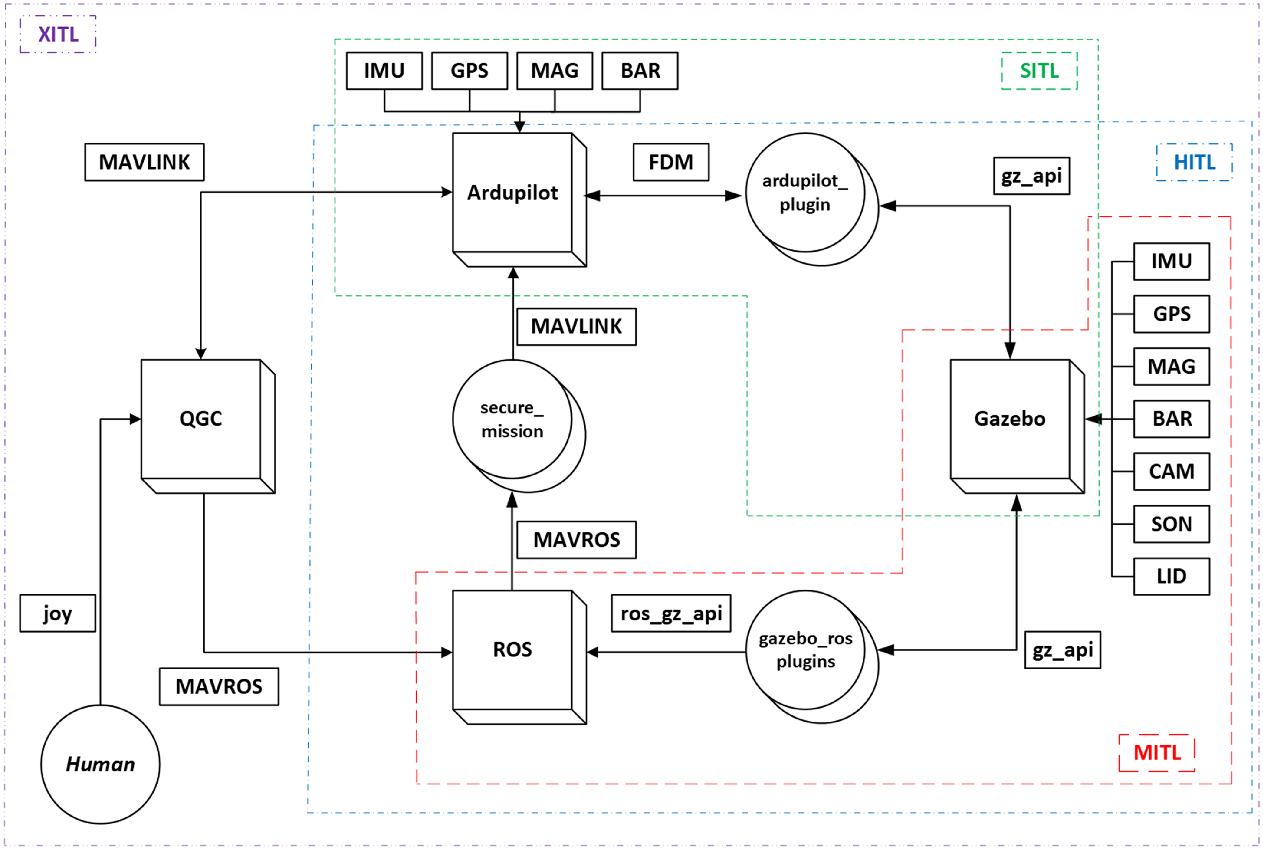
Regarding specified tools, we illustrate the proposed architecture in Figure 8, emphasizing its specific support for multiple technologies in a realistic simulation. Subsequently, we highlight the main elements that enable the application of various simulation methodologies, thereby clarifying the primary contribution of this proposal:
-
• Ardupilot_plugin: Adaptations in the source code of the ArduPilotPlugin source codeFootnote 1 for intercommunication between Gazebo and ArduPilot. Initially developed for standardized SITL simulations in ArduPilot itself, this plugin was modified to include passing messages from the Gazebo sensors to the interface with ArduPilot and enabling the implementation of HITL strategies.
-
• gazebo_ros_plugins: Codes for intercommunication between ROS and Gazebo. Essential communication elements are provided natively. Other specific elements, for example, for implementing low-level controllers, can be found in free repositories maintained by the software maintainer itself.Footnote 2
-
• Mavlink: Low computational cost communication protocol developed for micro-aerial vehicles. MAVLink follows a hybrid publish/subscribe and point-to-point communication pattern. It is responsible for communicating with the ground control station (GCS) and receiving ArduPilot commands sent by ROS. We created custom messages to transmit data from the sensors in Gazebo to ArduPilot.
-
• MAVROS: ROS package that provides a communication driver for several FCU software supported by MAVLink. Additionally, it provides a User Datagram Protocol (UDP) bridge between MAVLink and GCSs. We created custom ROS messages to transmit data from the sensors in Gazebo to ArduPilot.
-
• QGroundControl (QGC): GCS responsible for implementing a supervisory system that allows the user to interface safely and reliably with the vehicle.
-
• Human: A human operator is responsible for monitoring and defining, in the first instance, the objectives of the navigation and exploration missions in the environment of interest. This human operator is crucial in implementing HuITL techniques in dataset generation, deep network training, and real-time application.
-
• secure_mission: Codes responsible for implementing the computational intelligence elements of the architecture. It will comprise processing nodes for identifying and avoiding obstacles in the navigation route, regardless of the current missions.
-
• joy: Device for receiving radio control signals issued by the operator.
Simulation system architecture.

To support XITL simulations, specifically to enable the application of Model, Software, Hardware, Human, and other schemes, we propose the integrative and modular paths highlighted by dashed lines in Figure 8. In this case, it highlighted only the essential elements for implementing a specific version of the simulation system, making it possible to use a superior layer for generating stimuli and high-level outputs required in an application scenario, not necessarily equal to the one presented in the present case study.
In the case of the HITL simulation, any autopilot board supported by ArduPilot and any embedded hardware with computational capability to run ROS could be used. The next section presents the hardware resources used to validate this proposal. Before, it is necessary to define the specific elements of the current case study, which involves navigation of ASVs in dynamic and unstructured environments, which includes a customized vessel and the structure of the environment in the proposed system, according to the following subsections.
Once the elements for each simulation modality are defined, it is possible to obtain new adjacency matrices and proceed with relevant studies of computational complexity and intercommunicaion technologies to, among other tasks, allocate the necessary hardware resources.
The choice of software elements is a design decision, with the only requirement being that they are distributed solutions with facilities for interprocess communication.
3.1. ASV and embedded sensors simulation
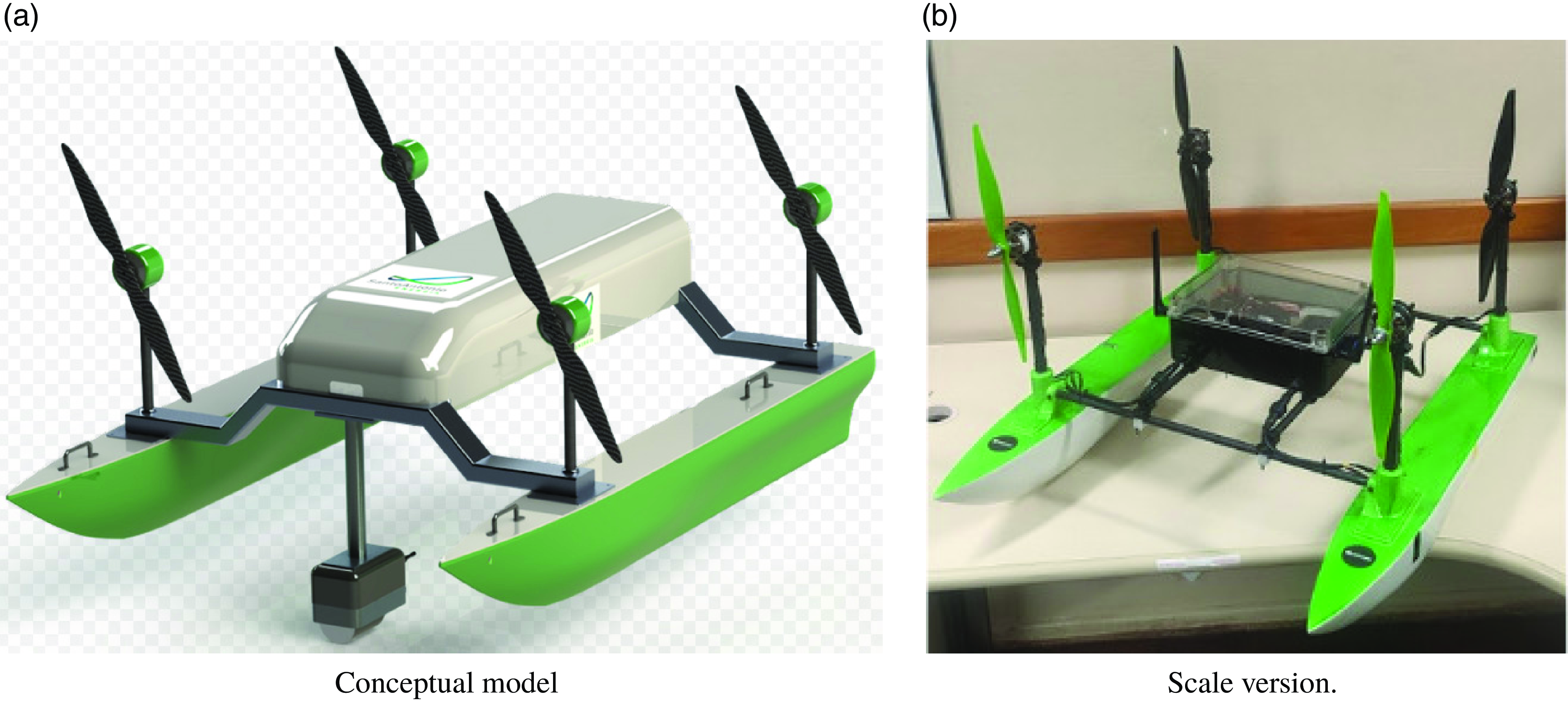
To meet the hydrodynamic requirements on water surfaces subject to submerged and floating obstacles, in addition to having the capacity to incorporate computational devices at different scales, a conceptual model of ASV with air propulsion was developed, as illustrated in Figure 9a. A scale version (1/3) was built and will be used to validate in practice the proposed novel architecture. Figure 9b shows this version.
ASV conceptual model and its built scale version.

This development builds on legacy solutions for air-powered surface vehicles as detailed in and [Reference da Silva, de Mello Honório, dos Santos, dos Santos Neto, Cruz, Matos and Westin35] and [Reference Regina, Honório, Pancoti, Silva, Santos, Lopes, Neto and Westin36]. As can be seen, this is a customized vehicle to meet the specific demands of the navigation environment, such as the profile of the hulls and propellers and a waterproof compartment for the onboard electronics. In addition to the constructive specifications, this vessel was sized to contain the processing nodes dedicated to implementing low- and high-level navigation strategies and various sensors such as GPS, Sonars, LiDARs, and Cameras.
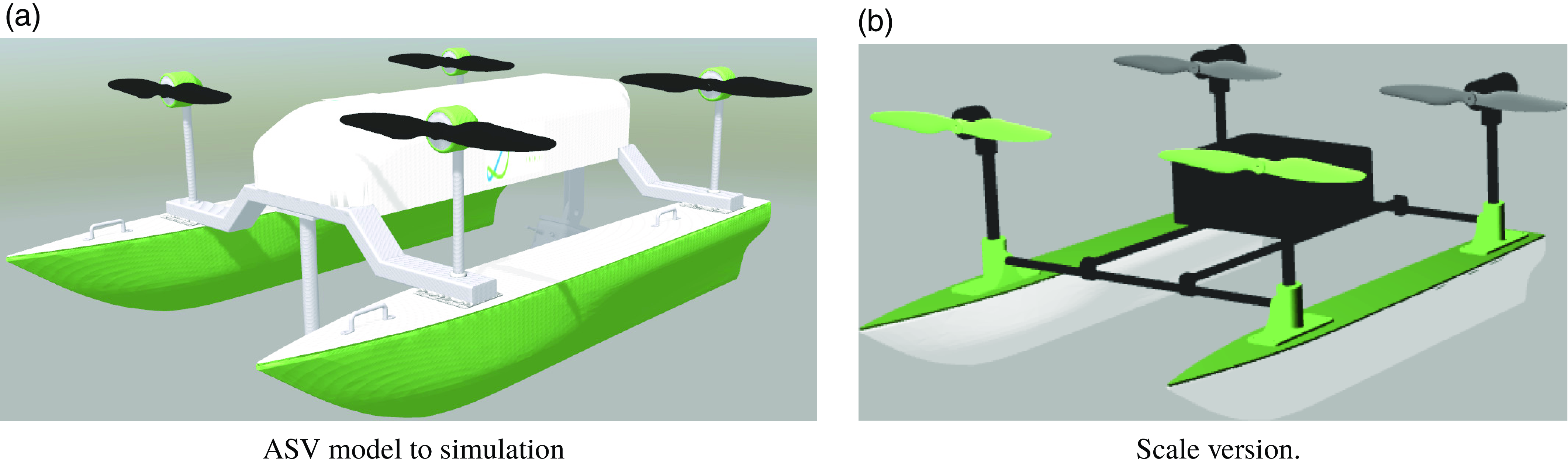
With the STL model of the conceptual vessel, after conversion to the DAE extension, directly supported by the computational tools specified above and the meeting of the initial construction parameters (geometry and inertia), a Gazebo model was built in SDF and URDF formats, enabling the individual use of the elements specified in Figure 10a illustrates the real size version of the simulated ASV and Figure 10b the scaled version.
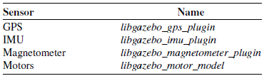
Several plugins are specified to provide the realistic character in the simulations with this vessel, available in open source for the Gazebo simulator. Table I illustrates the main plugins used to implement the requested functionalities.
Main plugins used in the simulated vessel1.

 $^1$
Available at: https://github.com/PX4/PX4-SITL_gazebo-classic.
To promote the required degree of realism, the collision models of these vessels were kept identical to the original 3D meshes in both cases, scaled or not. This choice does not compromise the computational performance of the simulations, given the large environmental dimensions and the high-definition graphic elements that make up the buildings to be detailed below.
ASV conceptual model and its built scale version.

3.2. Enviroment modeling
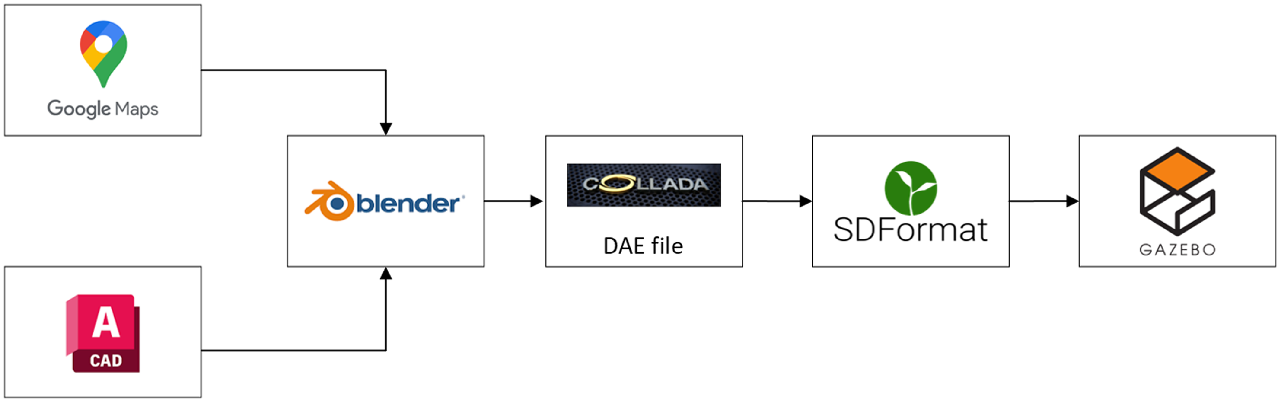
The simulated environment needs to efficiently reproduce natural aspects of the application in the most varied contexts. For this, the use of 3D modeling tools and high-precision plugins, which take environmental imperfections into account, is mandatory. Figure 11 illustrates a representative flowchart of the main tools for building a realistic simulation environment.
Main tools used for modeling the environment.

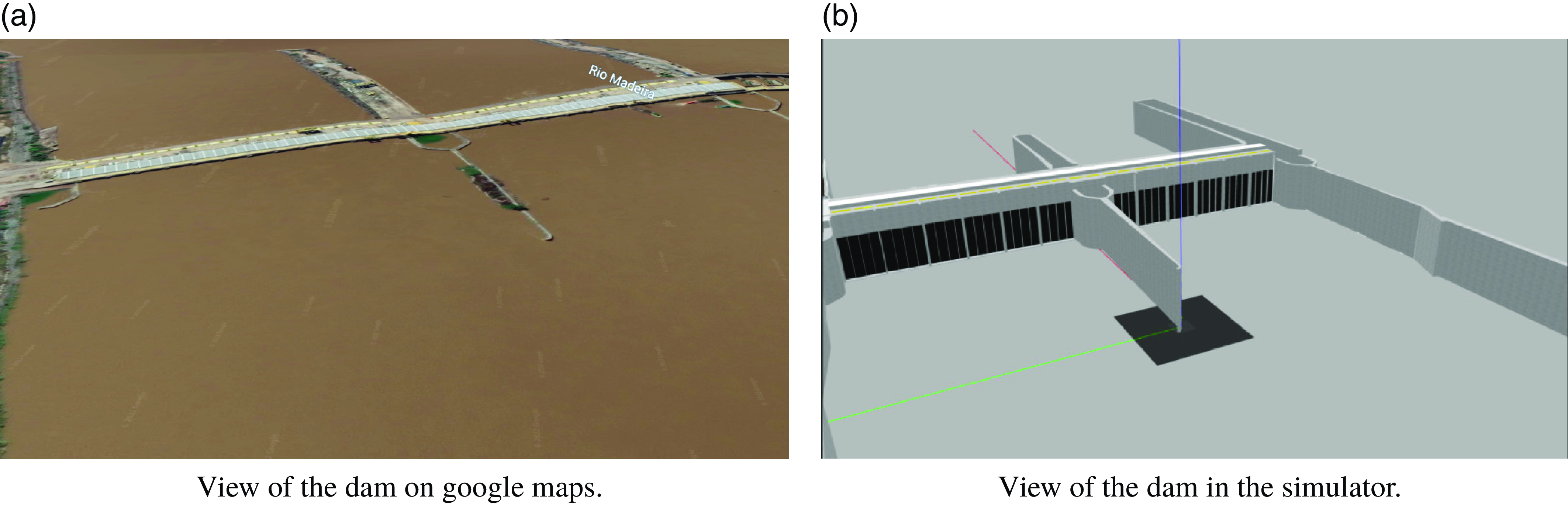
Google Maps generate an approximate 3D model for the margins and buildings, and after dimensional compliance through floor plans in Autocad, Blender generates the meshes of buildings and Log Boom. Figure 12 illustrates perspective views of the natural and simulated environment in the Gazebo software before including water models. Critical structural elements were contemplated, such as, for example, the dam grids and thresholds for the water intake, a critical visual monitoring point.
Views of the real and simulated dam.

As highlighted for the choice of the main elements of the integrated architecture, the choice of software for building the environment is the free choice of the designer.
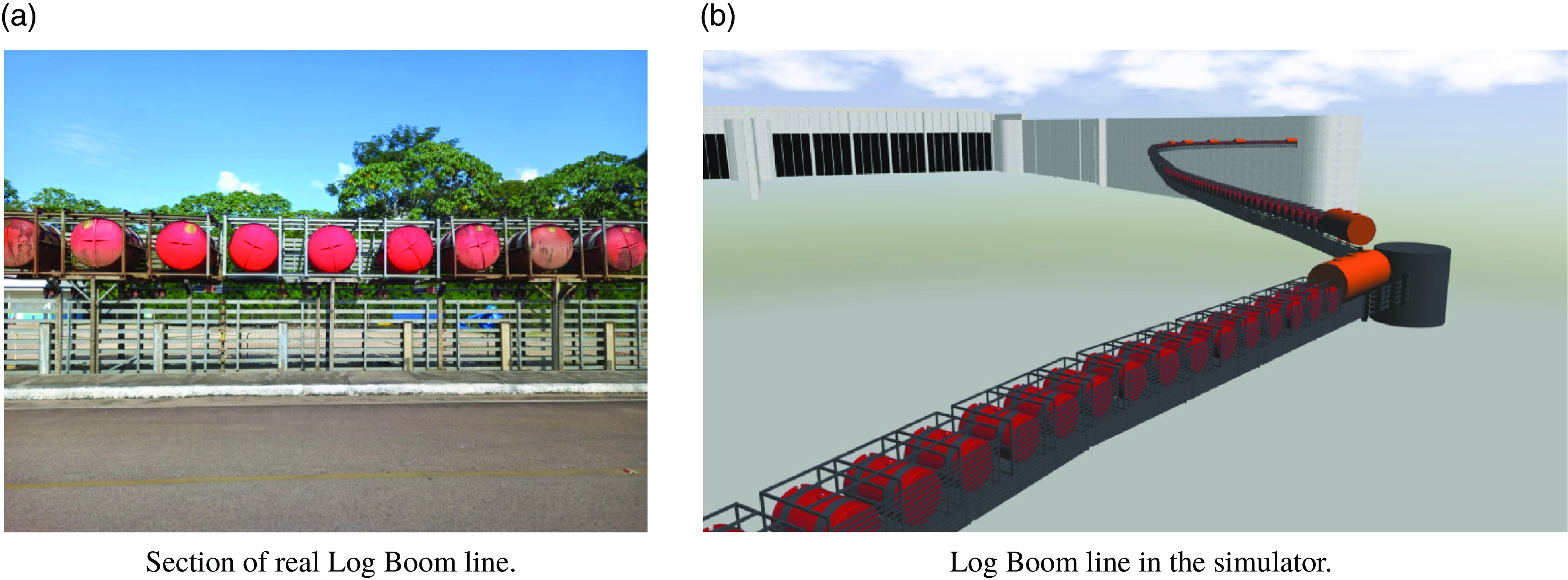
It is worth mentioning that, due to the actual dimensions of the installations in this part of the plant, to maintain the computational cost for the execution of the system, the collision models were simplified by simple geometric shapes. Another structure that must be modeled very accurately is the Log Boom so that there are the capabilities to interact with impurities typical of the monitoring zone in the actual application. Figure 13a illustrates a Section of Real Log Boom line and 13b detail of the developed Log Boom line model. Visual aspects are realistic and can promote the necessary feedback for the monitoring missions to be specified.
Views of the real and simulated Log Boom.

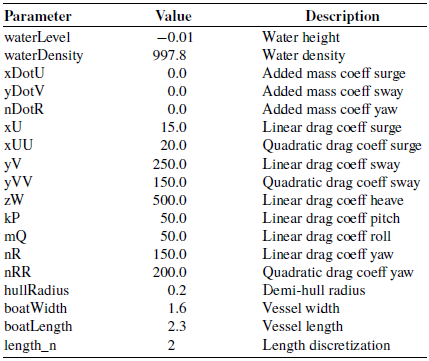
For hydrodynamic, we specify libgazebo_usv_dynamics_plugin plugin,Footnote 3 which is capable of including several hydrodynamic parameters, as illustrated in Table II, which also provides the values adopted in the initial version of the simulation system. The visual aspects and interaction with surface undulations were implemented through adaptations in the ocean_waves modelFootnote 4 to include the particularities of the application, after gathering various information obtained in the field.
Libgazebo_usv_dynamics_plugin plugin parametrization.

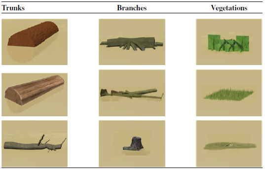
Other fundamental element contemplated in the simulation environment are the dynamic obstacles, which have particular aspects of buoyancy, flow in the river toward the dam. Table III brings together the main obstacles modeled in the initial versions of the system. The geometric, dynamic, and visual aspects of these obstacles can be modified at compile time directly in the SDF files so that it is possible to consider the generalities present in the natural navigation environment.
Main objects modeled in the simulation system.

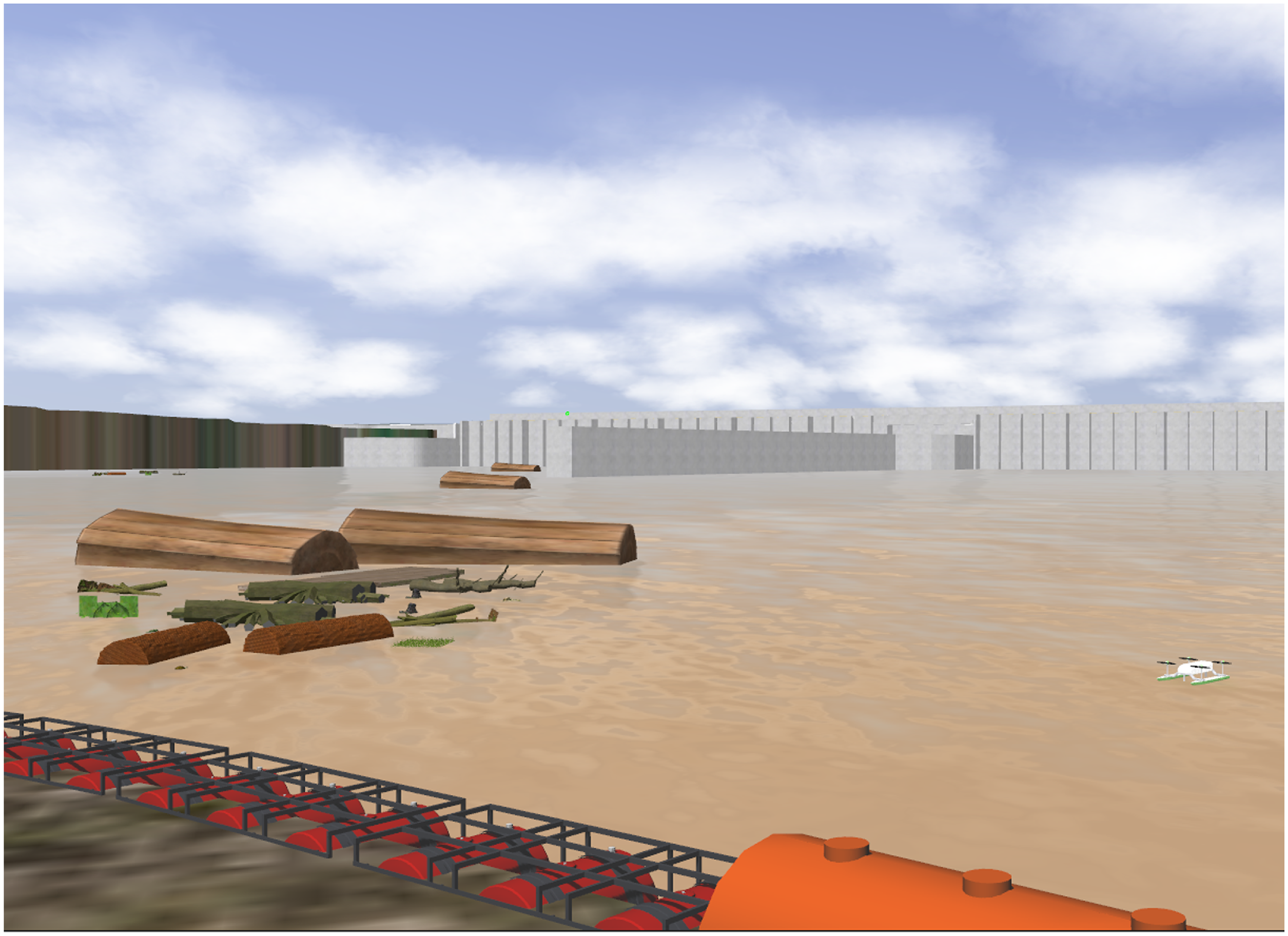
The developed solution allows the dynamic launch of obstacles in simulation time through ROS packages. In this way, the integrative capacity of this software is taken advantage of to validate the architecture in the most rigorous evaluation scenarios. After including all the elements listed in this subsection, the environment is shown in Figure 14.
Some other plugins were adapted from the above sources to contemplate natural phenomena typical of the present application, such as the simulation of water currents through forces and torque directly on the vehicle, additional buoyancy effects, and the simulation of random wind gusts. Thus, the developed environment allows the inclusion of seasonal climatic aspects in the simulation system, which is especially important in the proposal evaluation scenario.
View of the simulation environment in the Gazebo software.

4. Results
The availability of consolidated software and frameworks, such as the Gazebo simulator, ArduPilot, and ROS as the main actors of the proposed realistic simulation system, make the evaluation possibilities virtually endless, which is one of the main advantages of the proposal in the sense of contemplating specific characteristics of different types of application.
In this context, without loss of generality, the evaluations presented here are divided into four main scenarios, aiming to validate the environment and interactions with the simulated vessel and the global performance for a case of automatic exploration. The first test aims to evaluate the coherence between simulated navigation results and real results acquired with the scale prototype navigating in a practical testing environment.
The second test evaluates functionalities provided through the various specified plugins, aiming to verify the influence of water currents, waves, and winds on the effectiveness of SITL implementations.
In the third case, it will be possible to compare the performance of simulation strategies most used in real applications (SITL and HITL) for automatic missions to monitor heterogeneous obstacles in the Log Boom zone through mapping techniques based on LiDAR sensors.
Finally, results are presented and discussed with the multisensory perception system, composed of a Livox MID-70 LiDAR and a Blue Robotics Ping360 imaging sonar. As previously stated, this is a fundamental assessment for complete environmental monitoring under the conditions presented in this case study.
In all tests, a virtual joystick on the QGC screen provides the primary input commands, thus providing the paths for future implementations of HuTIL techniques. Notably, the other simulation modalities can be contemplated by removing or including specific elements in the basic architecture which are not critical for the overall behavior. For example, in a more straightforward case (MITL technique), remove the ArduPilot and generate the vessel commands directly through ROS topics. In another extreme, for a case of implementing the SyITL technique, it is enough to consider the whole system, including the ASV and practical sensors.
The simulations have a primary processing node composed of a general-purpose computer with the following basic specifications: Intel
 $^{\circledR}$
CoreTM i7-12700, 16 GB RAM, NVIDIA RTX3060 GPU, ubuntu 20.04 LTS. In the first instance, such an element is responsible for the execution of the Gazebo simulator, being able to implement the entire architecture in the specific case of implementation of the SITL technique.
Additionally, for HITL implementations, two more processing nodes are used:
-
• BeagleBone Black (AM335x 1 GHz ARM
$^{\circledR}$
Cortex-A8, 512 MB RAM, debian 10.3 (+ RT Kernell): Responsible for running ArduPilot and communicating with the primary processing node via standard ethernet over USB -
• NVIDIA Jetson (Quad-Core Arm
$^{\circledR}$
Cortex-A57, 128-core NVIDIA MaxwellTM GPU, 4 GB, ubuntu 20.04 LTS). Responsible for running ROS and communicating with the primary node through ethernet standard


The criteria that guide the specification of these elements were from evaluations of typical functionalities that need to be implemented in the practical application. In this case, we consider computational and energy performance for the execution of monitoring missions, which include, for example, 3D mapping of critical zones (strategies widely available in the ROS framework) with operational security guarantees (promoted by the ArduPilot autopilot).
With this set of hardware and software resources, implementing XITL techniques for the most varied performance requirements is supported. The video in the supplementary materials provides a better visualization of the main results.
4.1. Comparison between simulated and real ASV
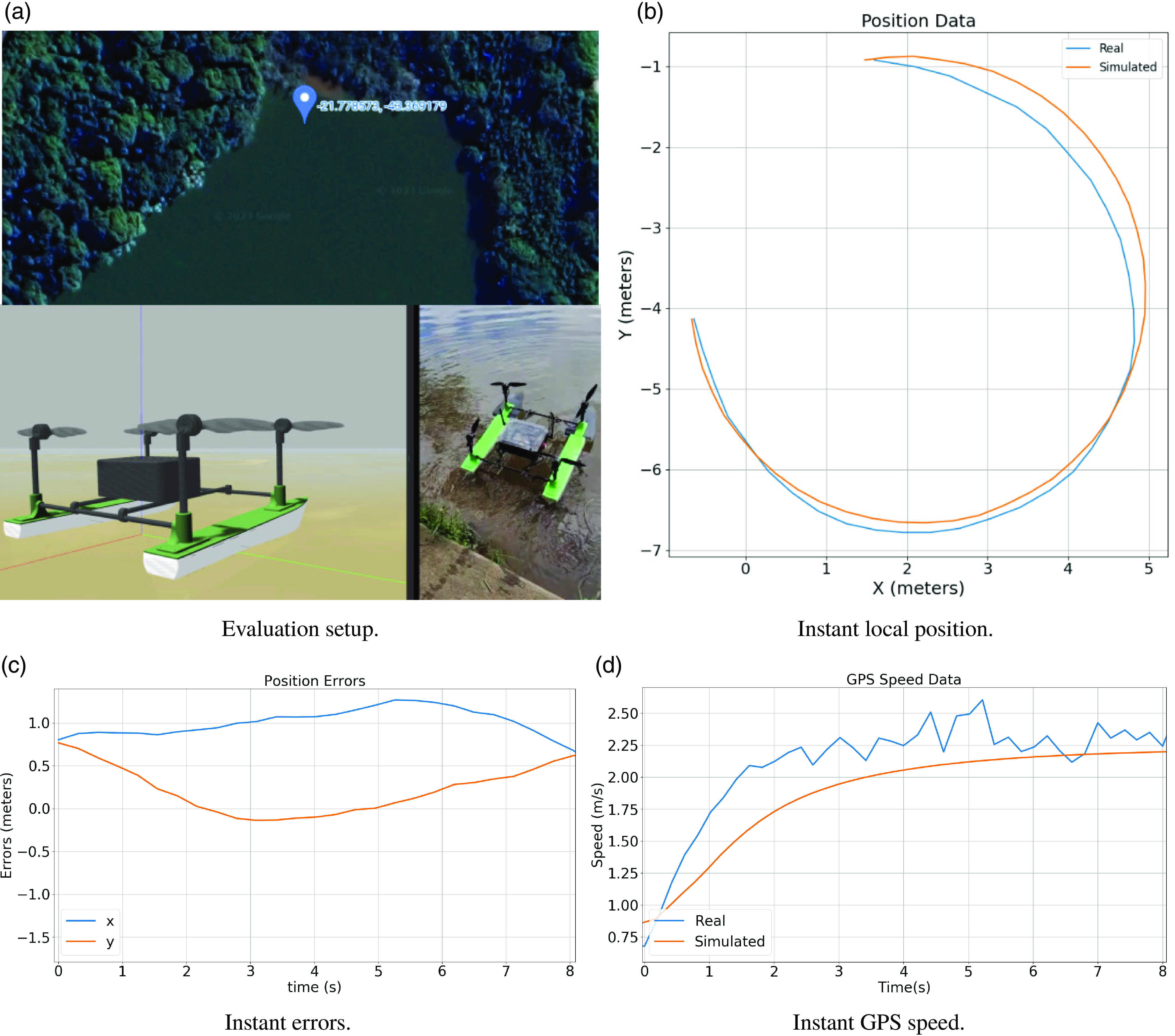
As a first evaluation, the scale prototype of the vessel was taken to a water test surface, aiming to demonstrate the validity of the proposed architecture. Figure 15a illustrates the vessel in the simulation environment and its physical prototype in the operational scenario.
Direct comparison between real and simulation data.

In the present case, the vessel navigates through manual commands from an operator connected to the QGC. Here, force and torque commands are sent directly to the vessel, which contains a version of ArduPilot embedded in a Pixhawk Cube Black, through appropriate radio communication channels (RCIN).
We obtained the data using an approximately circular arc trajectory and collected the actual Pulse Width Modulation (PWM) reference values (RCOUT) for application on the simulated vessel. The goal is to compare the performance of the real system with the simulated one, allowing us to assess the accuracy limits of the developed simulation environment.
The experiment with the physical system considers the QGC as a Driver. In contrast, in the simulation case, the driver only sends the data recorded in the experiment to the simulated vessel through the RCOUT commands. In both cases, the ArduPilot log tools act as the Monitor. For this scenario, we have the following adjacency matrices:
 \begin{align} A_{\text{ref}} = \begin{bmatrix} 0 & 1 & 1 & 1 & 1 & 0 & 0 & 0 & 0 \\[5pt] 1 & 0 & 1 & 1 & 1 & 0 & 0 & 0 & 1 \\[5pt] 1 & 1 & 0 & 1 & 0 & 0 & 0 & 0 & 1 \\[5pt] 1 & 1 & 1 & 1 & 1 & 0 & 0 & 0 & 1 \\[5pt] 1 & 1 & 0 & 1 & 0 & 0 & 0 & 0 & 1 \\[5pt] 0 & 0 & 0 & 0 & 0 & 0 & 0 & 0 & 0 \\[5pt] 0 & 0 & 0 & 0 & 0 & 0 & 0 & 0 & 0 \\[5pt] 0 & 0 & 0 & 0 & 0 & 0 & 0 & 0 & 0 \\[5pt] 0 & 1 & 1 & 1 & 1 & 0 & 0 & 0 & 0 \\[5pt] \end{bmatrix}; \end{align}
 \begin{align} A_{\text{sim}} = \begin{bmatrix} 0 & 1 & 0 & 0 & 0 & 0 & 0 & 0 & 0 \\[5pt] 1 & 0 & 1 & 1 & 1 & 0 & 0 & 0 & 1 \\[5pt] 0 & 1 & 0 & 1 & 0 & 0 & 0 & 0 & 1 \\[5pt] 0 & 1 & 1 & 1 & 1 & 0 & 0 & 0 & 1 \\[5pt] 0 & 1 & 0 & 1 & 0 & 0 & 0 & 0 & 1 \\[5pt] 0 & 0 & 0 & 0 & 0 & 0 & 0 & 0 & 0 \\[5pt] 0 & 0 & 0 & 0 & 0 & 0 & 0 & 0 & 0 \\[5pt] 0 & 0 & 0 & 0 & 0 & 0 & 0 & 0 & 0 \\[5pt] 0 & 1 & 1 & 1 & 1 & 0 & 0 & 0 & 0 \\[5pt] \end{bmatrix}. \end{align}
The weighting vectors are given as follows:
 \begin{align} W_{\text{ref}} = \begin{bmatrix} 1.0 & 1.0 & 1.0 & 1.0 & 1.0 & 0.0 & 0.0 & 0.0 & 1.0 \\ \end{bmatrix}; \end{align}
 \begin{align} W_{\text{sim}} = \begin{bmatrix} 0.5 & 0.5 & 0.5 & 0.5 & 0.5 & 0.0 & 0.0 & 0.0 & 0.5 \\ \end{bmatrix}. \end{align}
With this configuration and considering
 $\overline{d}_{\text{ref}} = \overline{d}_{\text{real}}$
and WDRI = 0.36; that is, the comparison results are expected to be at least 36% faithful.
Figure 15b shows that a trajectory consistent with that performed by the real vessel was executed, with a slight difference observed in specific sections, especially in the intermediate moments of the observation. However, these values were obtained through GPS data transformed into local coordinates, being tolerable values when considering the precision of this form of localization.
Figure 15c confirms this observation, indicating that the longitudinal and transversal position errors were constrained to a maximum of 1.25 m, acceptable values in various application contexts. Fine-tuning the hydrodynamic parameters of the simulated vessel can compensate for such errors.
Figure 15d depicts a consistent speed profile for both the real and simulated cases, affirming the coherence of the assessments conducted in simulation.
Quantitatively, we obtain the IAE (Integral of Absolute Error) given by
 $\int _{i=0}^{T_{END}} \left | f(t) - h(t) \right | dt,$
where
 $ T_{END}$
is the final time,
 $f(t)$
is the real instant value,
 $h(t)$
is the simulated instant value. For the acquired data, we get
 $\text{IAE}_x$
= 3.87 m and
 $\text{IAE}_y$
= 1.4 m. Considering that the accumulated distance error is 35% lower than the average accuracy value of commercial GPSs (considered 6 m), a value close to that obtained for WDRI in the present simulation, enforcing that the simulation results are consistent.
This confirmation enables the development of simulations using the original version of the vessel even before its physical construction.
4.2. Enviroment and ASV analysis
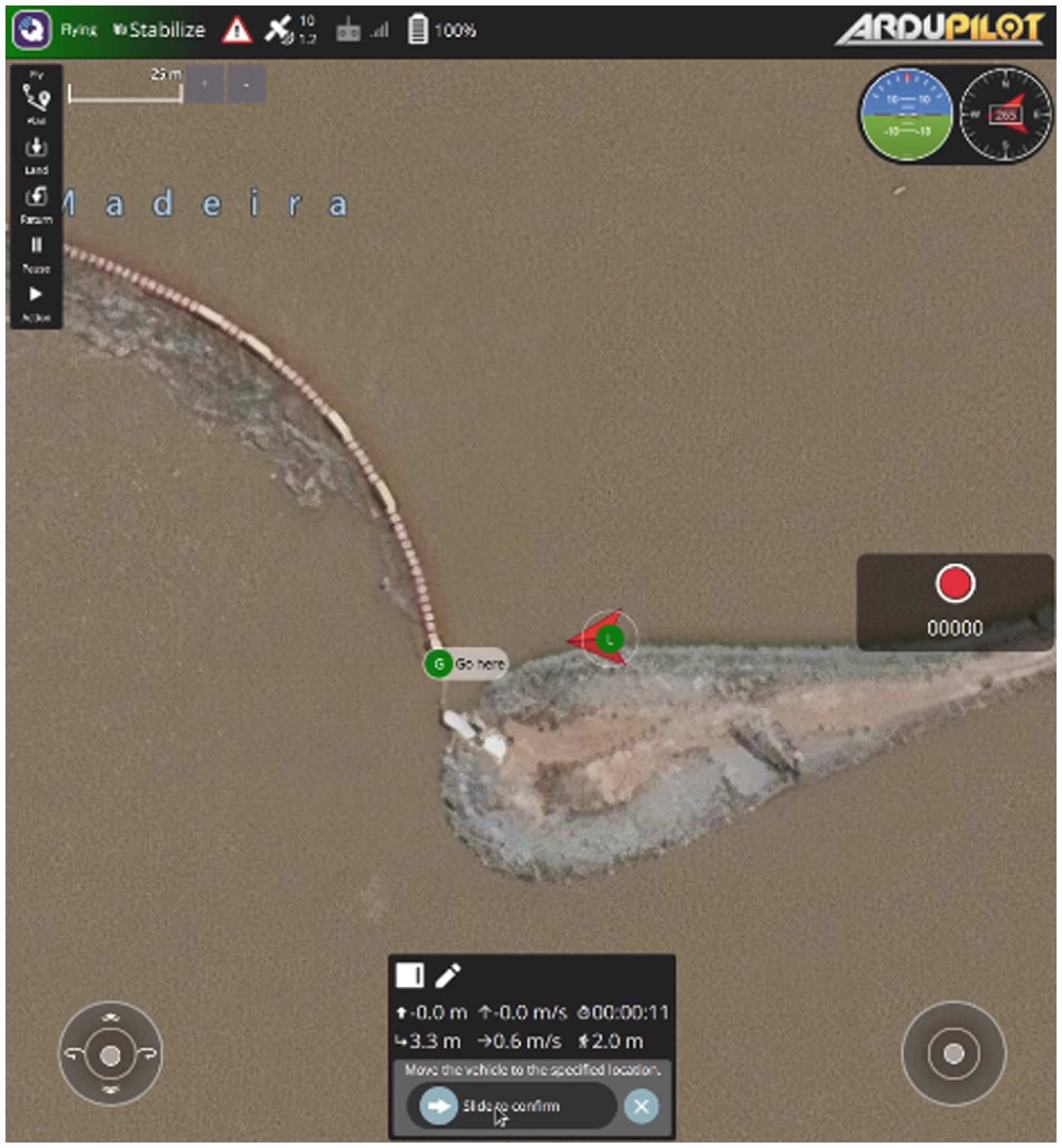
This second test consists of arming the vehicle and waiting for the entry into “STABILIZE” mode to manually send a waypoint in the Log Boom region, as shown in Figure 16. In this case, the system automatically enters “GUIDED” mode and applies the necessary control actions to track the reference coordinate, developing a maximum speed specified through the “WP_NAV_SPPED” parameter, defined here as 3 m/s.
First evaluation QGC screen.

For this first evaluation, we use the standard SITL technique, that is, the sensors simulated on the ArduPilot side, as per the SITL solution initially provided by the ArduPilot developers.
Since we including QGC, the adjacency matrix is given as follows:
 \begin{align} A = \begin{bmatrix} 0 & 1 & 1 & 1 & 1 & 0 & 0 & 0 & 0 \\[5pt] 1 & 0 & 1 & 1 & 1 & 0 & 0 & 0 & 1 \\[5pt] 1 & 1 & 0 & 1 & 0 & 0 & 0 & 0 & 1 \\[5pt] 1 & 1 & 1 & 0 & 1 & 0 & 0 & 0 & 1 \\[5pt] 1 & 1 & 0 & 1 & 0 & 0 & 0 & 0 & 1 \\[5pt] 0 & 0 & 0 & 0 & 0 & 0 & 0 & 0 & 0 \\[5pt] 0 & 0 & 0 & 0 & 0 & 0 & 0 & 0 & 0 \\[5pt] 0 & 0 & 0 & 0 & 0 & 0 & 0 & 0 & 0 \\[5pt] 0 & 1 & 1 & 1 & 1 & 0 & 0 & 0 & 0 \\ \end{bmatrix}. \end{align}
In such a case, we must consider
 $\overline{d}_{\text{ref}} = \overline{d}_{\text{sim}} = 4$
since we are aiming to evaluate the simulation relative to the general usage architecture illustrated in Figure 6. For these quantities, WDRI = 0.28.
This test was performed three times considering the following environmental conditions:
-
• Case 1 - Ideal environment
-
• Case 2 - Water currents and waves
-
• Case 3 - Water currents, waves and wind gusts
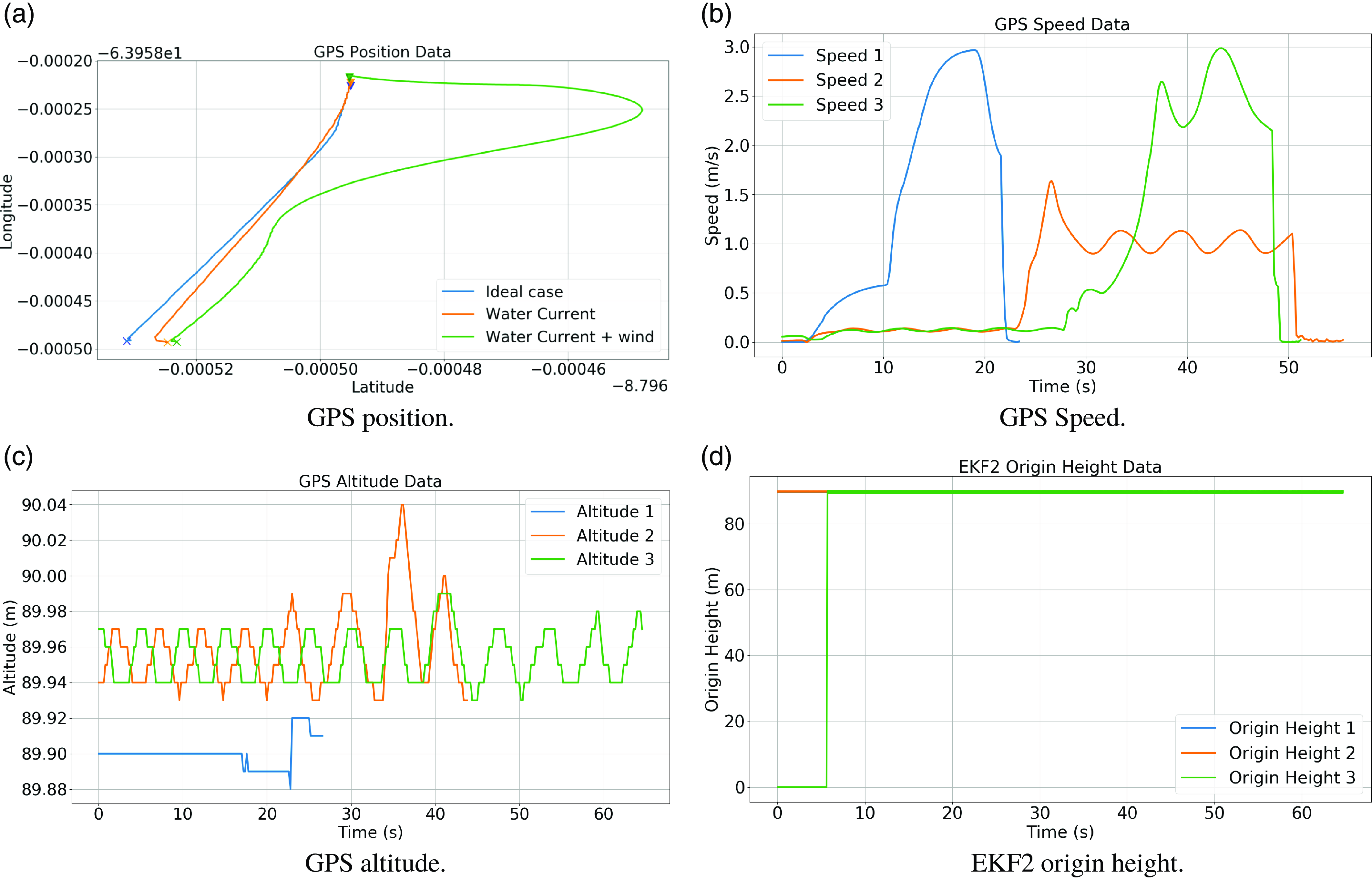
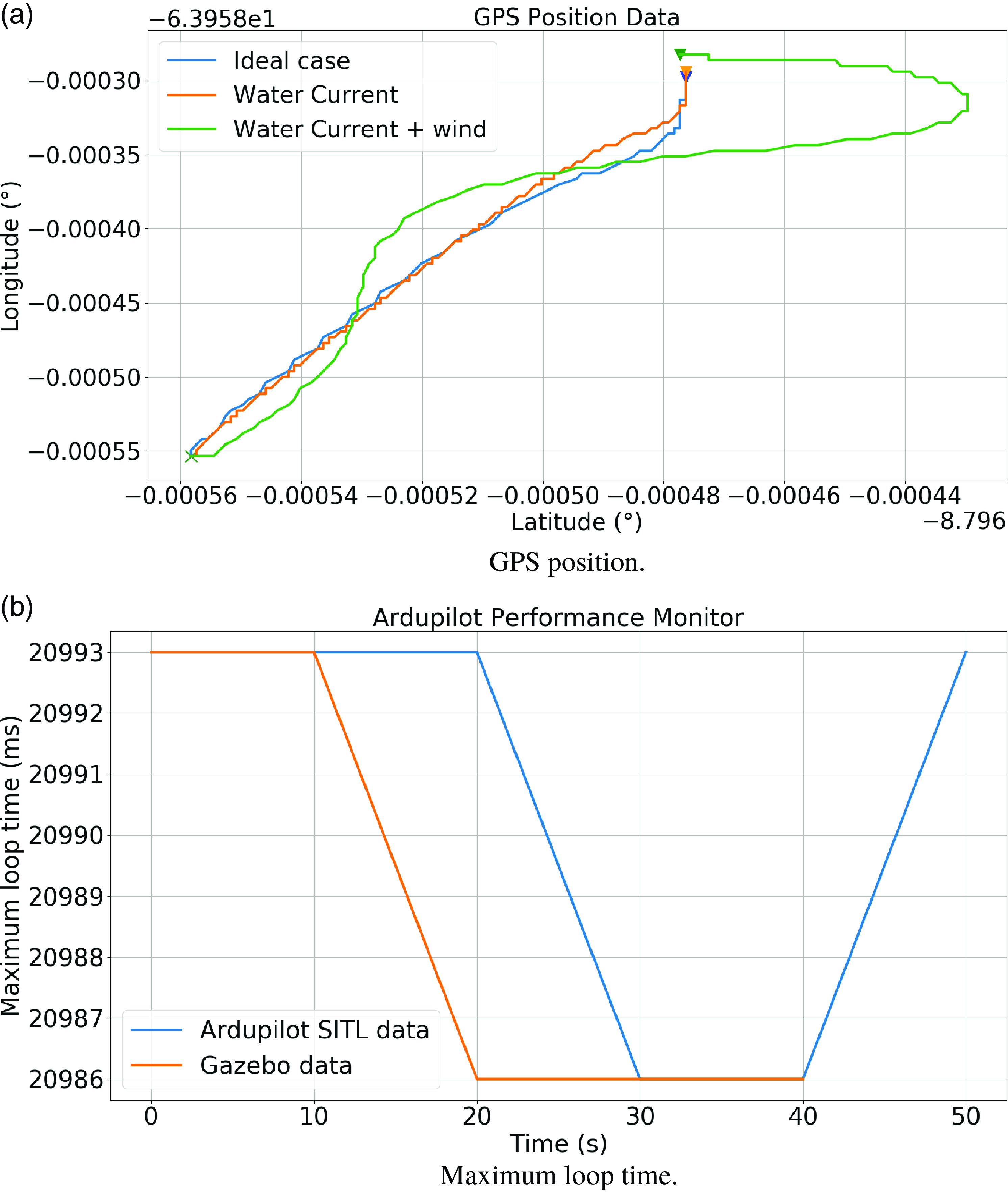
Figure 17 provides the results of this evaluation. It is possible to notice in Figure 17a that there was no considerable loss of performance with the inclusion of currents and waves (case 2), with only temporal losses made explicit through the velocity curves illustrated in Figure 17b.
Environments imperfections evaluating – SILT implementation.

Figure 17c shows the influence of imperfections in the altitude curves through a sinusoidal pattern consistent with the visual behavior and physical specifications contemplated through the plugins. Even though GPS is not the most appropriate sensor for measuring submetric variations, this result clarifies the influence of intentionally added environmental imperfections.
Still, in these figures, it is possible to notice a considerable loss of performance for case 3, which is justified by the significant variability in the global pose of the vessel, which prevents rapid convergence of the localization algorithms implemented in ArduPilot. Among the parameters that most diverged among the simulations, Figure 17d highlights the origin height for the execution of Extended Kalman Filter algorithm. Note that the delay in this definition was propagated, causing the movements to begin only about the 30 s after the ideal case.
EKF2 origin height analysis.

Performance with Gazebo sensors.

This result confirms the importance of this type of evaluation, as such a convergence delay could be enough time for the vessel to be hit by an obstacle or even suffer from other more harmful effects that do not only involve the loss of financial resources. Additionally, a distributed architecture is justified because, in case of failure in one of the computational abrasion levels, another can take over the vessel’s movements to avoid significant problems.
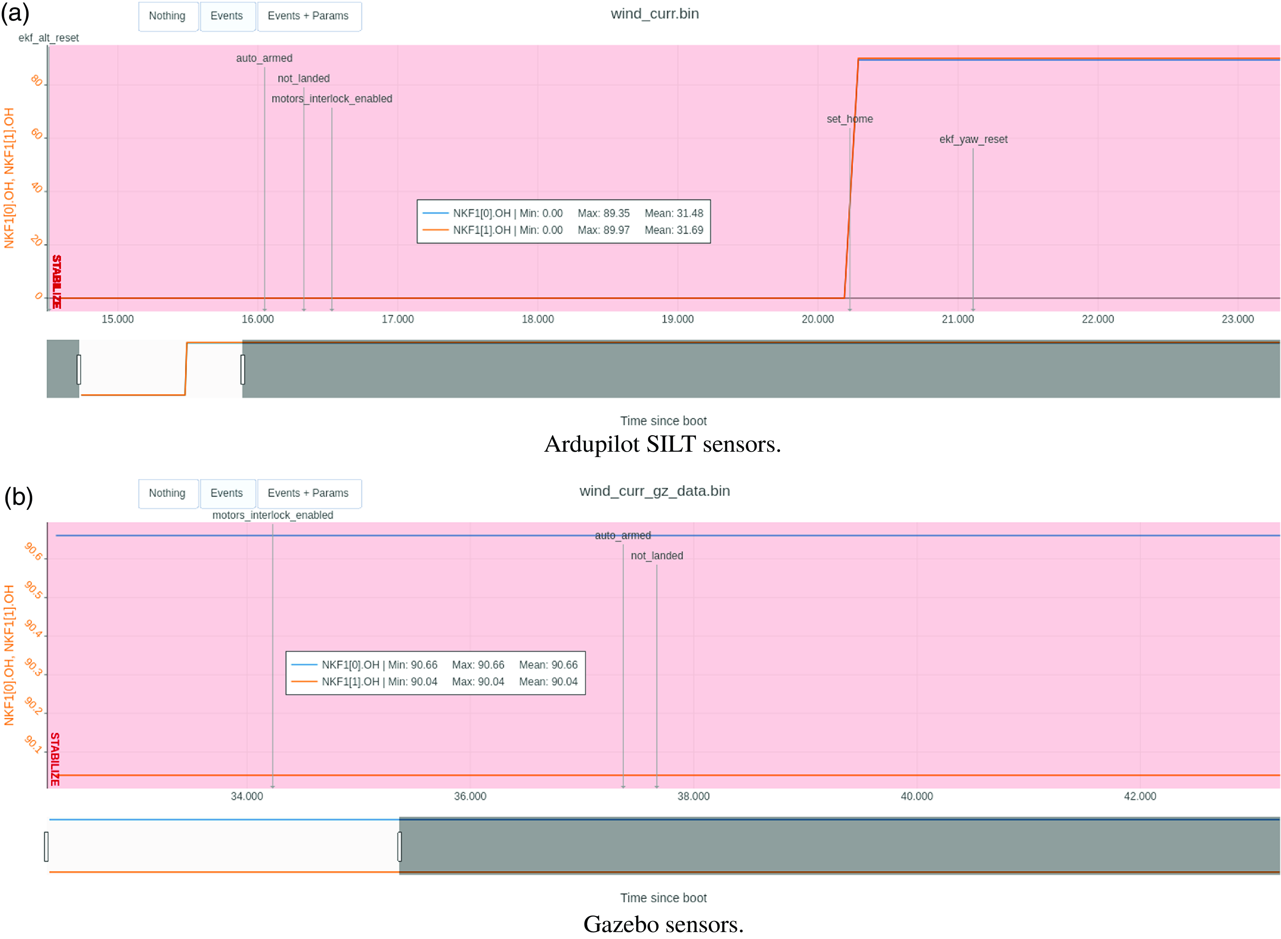
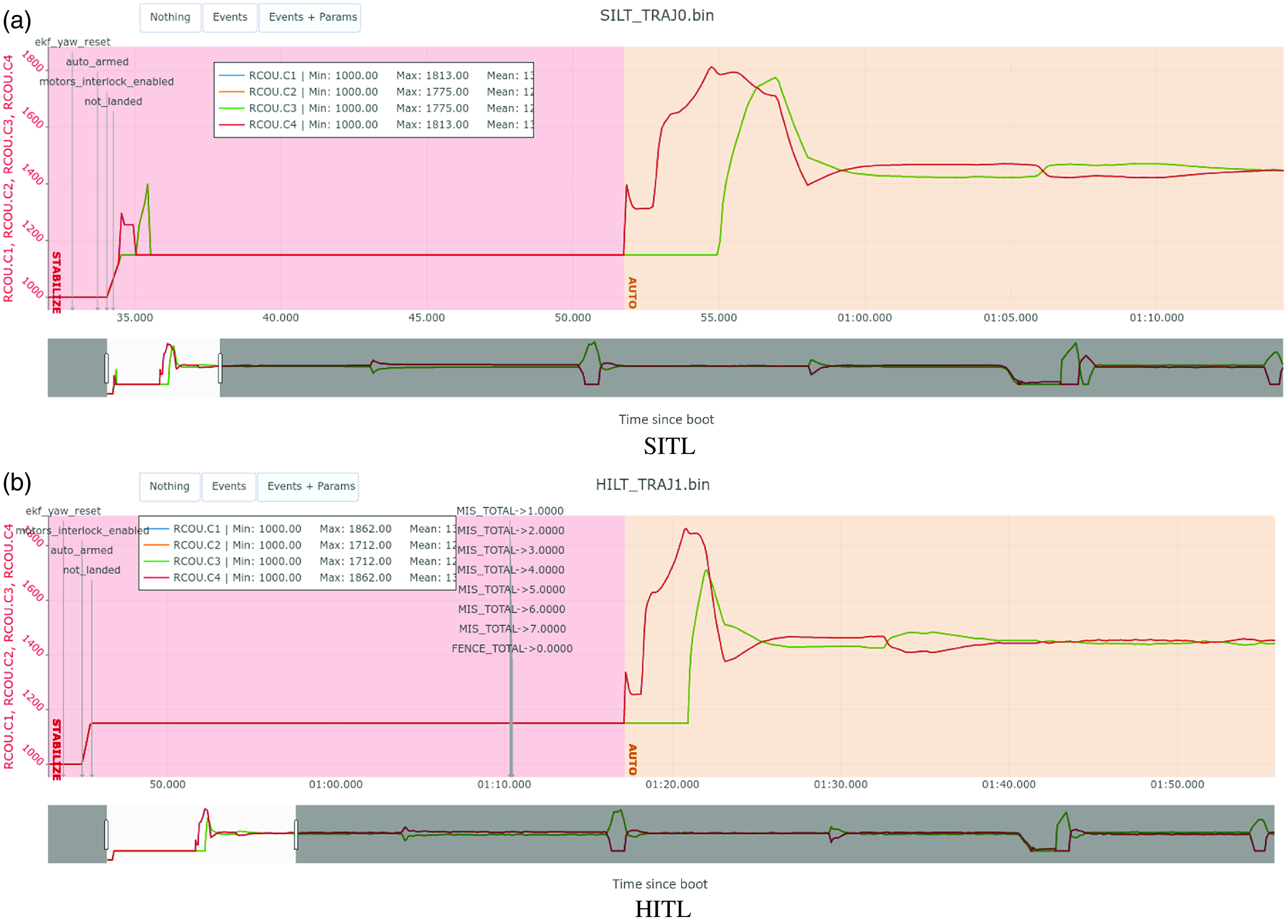
Given this result, specifically concerning the behavior illustrated in Figure 17d, a detailed analysis of the standard ArduPilot .bin log files uploaded through the online tool UAV Log Viewer Footnote 5 is carried out, with the results illustrated in Figure 18. It is possible to note several events that prevent the convergence of the localization for the ArduPilot native sensors of the SITL implementation, which does not occur when including the sensory data from the Gazebo simulator, as illustrated in Figure 18b.
This is justified by including an exclusive communication channel for the reception of sensor signals directly from the Gazebo, making the sensing independent of additional processing in the ArduPilot execution stack, making the solution more realistic, including for the SITL simulations themselves. For the latter case, we have the following adjacency matrix:
 \begin{align} A = \begin{bmatrix} 0 & 1 & 1 & 1 & 1 & 1 & 0 & 0 & 0 \\[5pt] 1 & 1 & 1 & 1 & 1 & 1 & 0 & 0 & 1 \\[5pt] 1 & 1 & 0 & 1 & 0 & 1 & 0 & 0 & 1 \\[5pt] 1 & 1 & 1 & 0 & 1 & 1 & 0 & 0 & 1 \\[5pt] 1 & 1 & 0 & 1 & 0 & 0 & 0 & 0 & 1 \\[5pt] 1 & 1 & 1 & 1 & 0 & 0 & 0 & 0 & 1 \\[5pt] 0 & 0 & 0 & 0 & 0 & 0 & 0 & 0 & 0 \\[5pt] 0 & 0 & 0 & 0 & 0 & 0 & 0 & 0 & 0 \\[5pt] 0 & 1 & 1 & 1 & 1 & 1 & 0 & 0 & 0 \\ \end{bmatrix}. \end{align}
The entries related to the column/row of the
 $PS$
vertex became unitary to contemplate the connectivity of the resources simulated in the Gazebo and the other processes. In this case, we get WDRI = 0.42, representing an increase of 50% in the simulation’s realism.
Repeating the three tests for the sensory data produced by the Gazebo, the results of Figure 19 are obtained. It is possible to notice a greater consistency in the results even under the influence of distinct natural imperfections. Comparing this result with the previous one for case 3, Figure 19b shows, through the maximum loop time parameter (MaxT)Footnote 6 made available by ArduPilot, that there is no loss of performance as a result of the inclusion, in addition to that the stability for the execution of the movements takes place about 10 s before.
4.3. SITL X HITL analysis
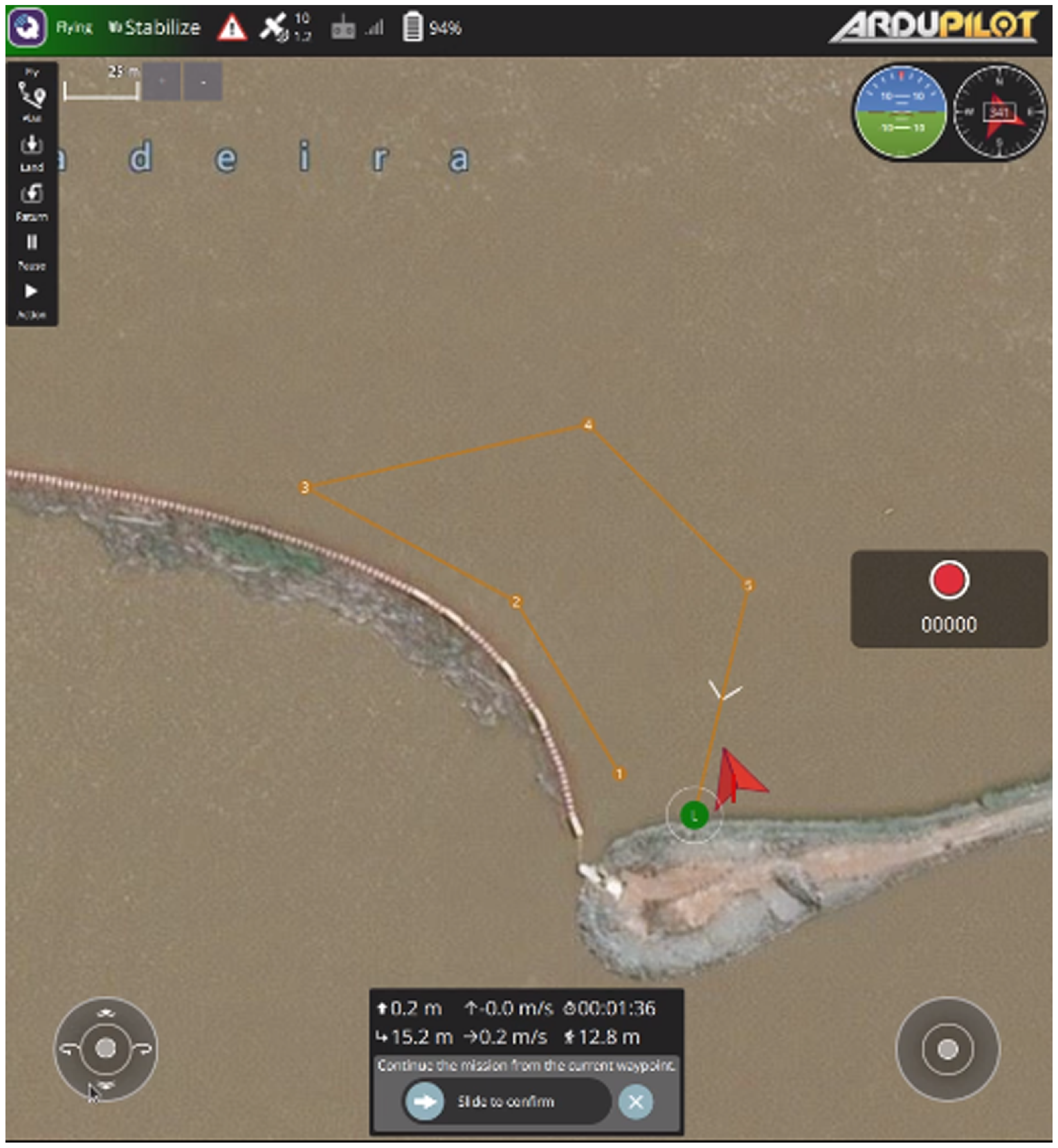
Considering the previous results, we set the Gazebo simulator as a provider of sensory data, and a mission is defined directly from the QGC interface, as illustrated in Figure 20.
The objective is to certify the consistency between the SITL and HITL cases made possible by the proposed architecture, even without direct support for HITL evaluations in ArduPilot and considering limited hardware resources for implementing low-level applications.
In the HITL case, there is no change in the adjacency matrix about the previous case due to the agnostic nature of the proposed solution, which makes it independent of the hardware that implements the processing nodes. However, the degree of realism of this simulation is naturally higher, and this is covered by a new weight vector given as follows:
 \begin{align} W_{\text{sim}} = \begin{bmatrix} 0.5 & 0.5 & 1.0 & 1.0 & 1.0 & 0 & 0 & 0 & 1.0 \\ \end{bmatrix}. \end{align}
With these values, the WDRI increases to 0.58, making the fidelity of the results even greater.
QGC screen of evaluation scenario.

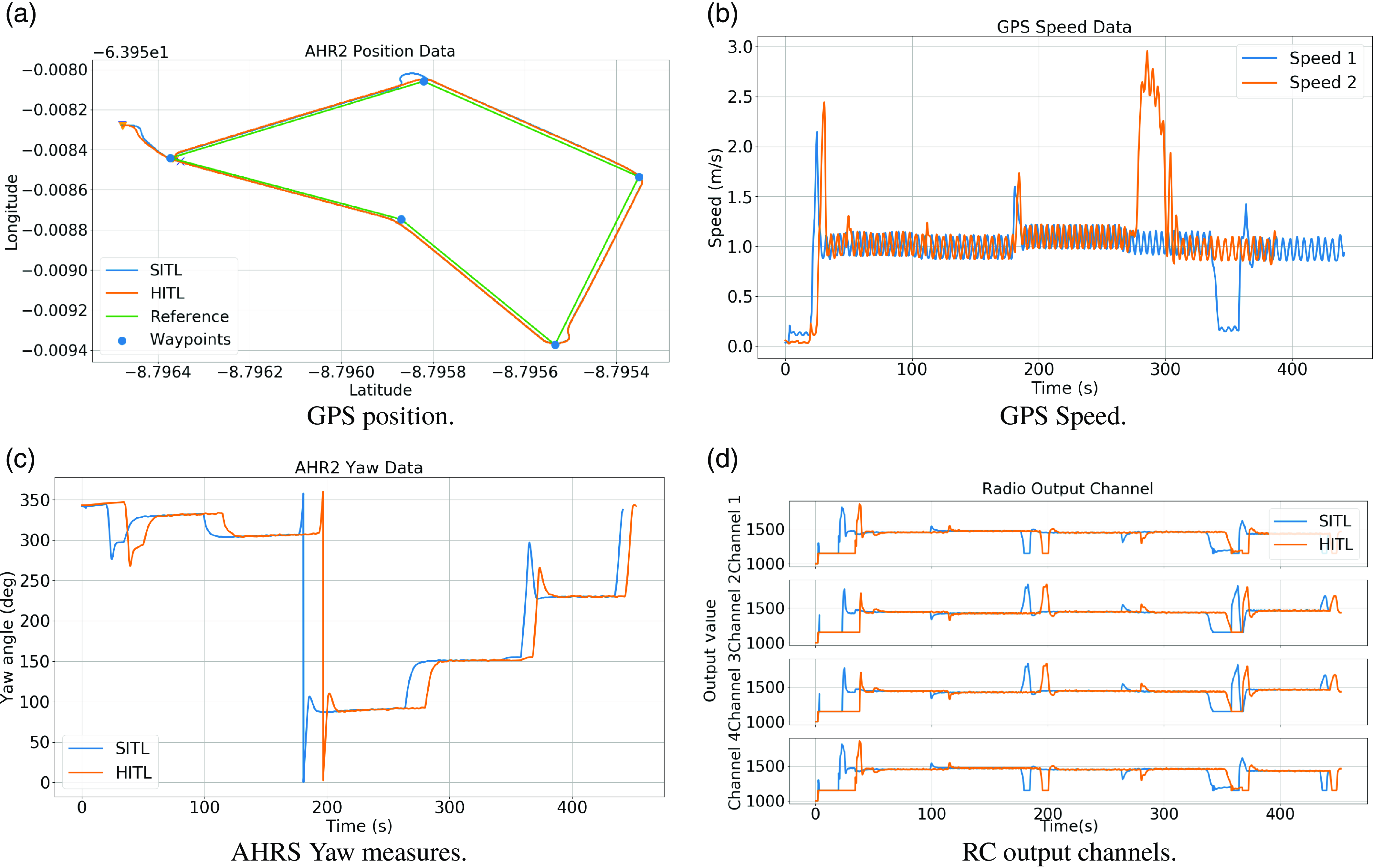
SITL and HITL results.

RC channels and events.

Aiming to validate the high-level processing node in a context that involves a large flow of data and reasonable computational power requirements, data from the Livox Mid-70 sonar and the Loam algorithm made available by the LiDAR manufacturer itself through the livox_mapping package.Footnote 7
With this specification, it will be possible to map obstacles in the Log Boom zone, which under the influence of currents and winds, tend to invade the dam’s adduction zone, compromising the entire process of the hydroelectric plant. By capturing the states of impurities in this region, it will be possible to support operational decision-making for maintaining the physical integrity of equipment and crisis management in different contexts.
It is worth mentioning the importance of validating the proposal in a scenario that involves a high flow of data through networks implemented through different standards (specifically, USB on the ArduPilot side and ethernet on the ROS side), evaluating the execution of the complete mission as a complete success, meeting minimum operational security requirements in computational terms, reflected through the maintenance of all ArduPilot standard security parameters.
With the inclusion of the nodes related to the high-level tools (supernode
 $H$
), the adjacency matrices becomes identical to (24) and the weighting vectors are given as follows:
 \begin{align} W_{\text{SITL}} = \begin{bmatrix} 0.5 & 0.5 & 0.5 & 0.5 & 0.5 & 0.5 & 0.5 & 0.5 & 0.5 \\ \end{bmatrix}; \end{align}
 \begin{align} W_{\text{HITL}} = \begin{bmatrix} 0.5 & 0.5 & 1.0 & 1.0 & 1.0 & 1.0 & 1.0 & 1.0 & 1.0 \\ \end{bmatrix}. \end{align}
With these values, we obtain
 $\text{WDRI}_{\text{SITL}}=0.54$
and
 $\text{WDRI}_{\text{HITL}}=0.93$
, a higher degree of confidence attested for HITL simulations.
Figure 21 illustrates the results obtained. The mission was completed satisfactorily in both cases (Figure 21a). The GPS speed and yaw angles measured by the onboard AHRS exhibit similar performance, as shown in Figure 21b and Figure 21c, respectively. It is possible to notice coherent control actions in the radio control channels (Figure 21d) less than a delay for the beginning of the executions in the HITL case.
This performance is expected due to the limitations of the computational platform used to implement ArduPilot and the absence of specific adjustments in the native localization algorithms. This delay in system startup in HITL can be better visualized through the analyses illustrated in Figure 22. There are signs of similar events at the beginning of the arming process. However, for the HITL case, scheduler deadline missed events are highlighted tasks, which partially explain the observed latency.
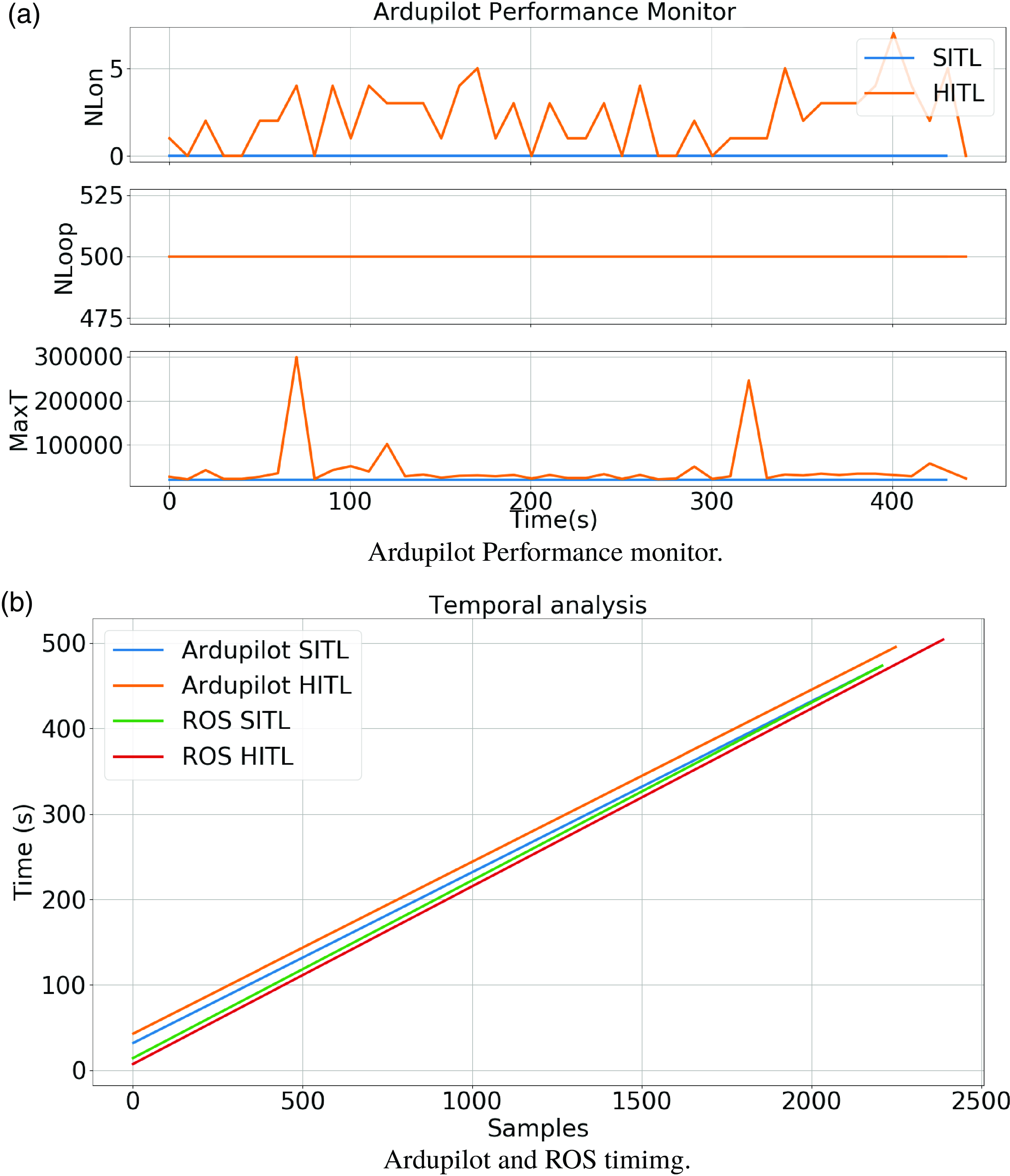
To further highlight this phenomenon, Figure 23a shows some magnitudes of the performance analyzer of ArduPilot itself. It is worth highlighting the parameter “Maximum Loop Time” (maxT) which reaches 300000 us in the case of arming in HITL simulations. However, this value is within limits specified by the ArduPilot developers for a reliable arming process, which justifies the success in fulfilling the mission in later moments.
Performance evaluation.

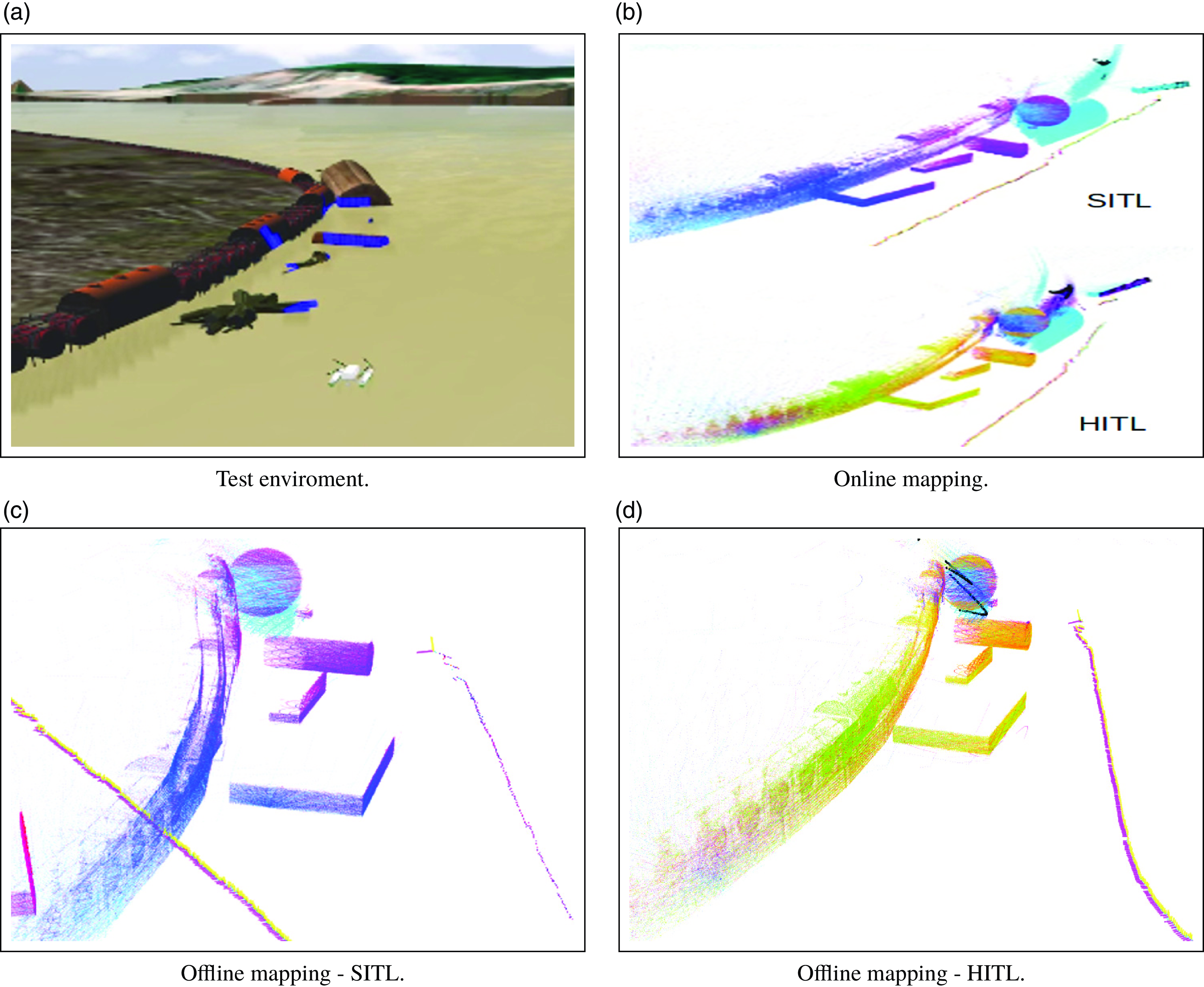
Mapping result.

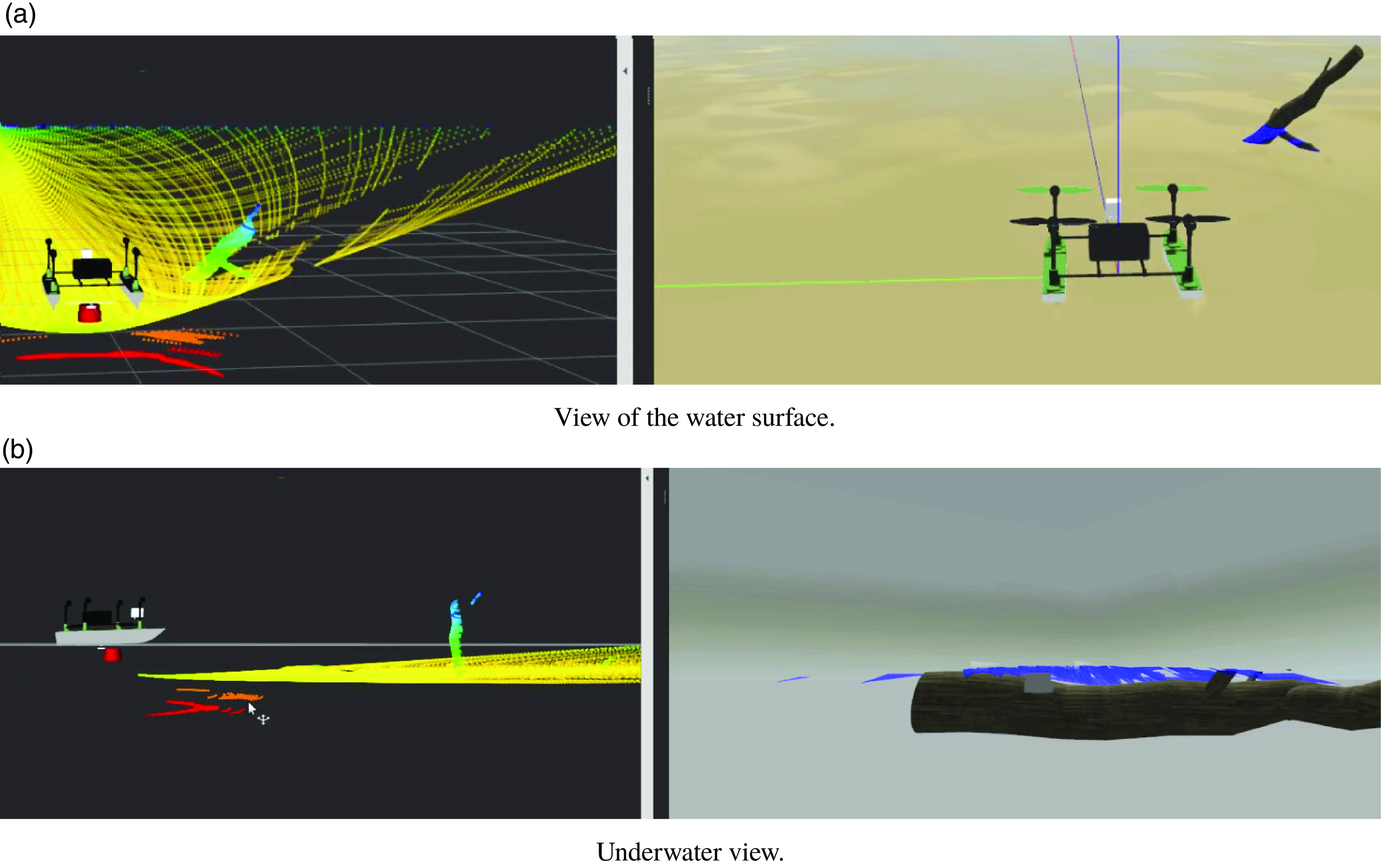
Multisensory point cloud.

To prove the coherence of the temporal bases between ArduPilot and ROS, even without the latter contemplating applications in hard real-time systems in its original version, the time curves measured by the number of samples are presented in Figure 23b. It is possible to notice a constant inclination toward the HITL case at both levels of implementation, which represents a fundamental characteristic for operational guarantees in a practical context where long-term operation is expected due to the dimensions of the monitoring zones. This figure also shows a slight variation in the inclination of the time bases for the SITL case, which may compromise the effectiveness of more extended simulations.
Finally, Figure 24 illustrates the obstacles and Log Boom mapping results for the SITL and HITL simulations in two modalities: online, where the mapping results were extracted from the RVIZ screen view, and offline through the execution of the recorded logs through the rosbag tool. Due to the global demand for computational power for SITL simulations, there is a slight discrepancy in the offline case, especially when looking at the LiDAR-based visual odometry profile, as illustrated in Figure 24c. This is due to the large volume of data that needs to be stored, through which effective reproduction has limitations for the SITL case.
All results presented in this section can be better visualized through videos at supplementary materials.
4.4. Multisensor perception
Concluding the analysis with the proposed architecture, this stage includes underwater perception through a plugin for implementing the Ping360 imaging sonar. As illustrated in Figure 2b, this is a fundamental implementation to validate navigation algorithms in a challenging scenario established for evaluating the proposed architecture.
Using the plugin proposed by [Reference Cerqueira, Trocoli, Neves, Joyeux, Albiez and Oliveira37] as a foundation, we made the necessary adjustments to accommodate the technical specifications of Ping360. We developed a ROS package to fuse Sonar and LiDAR point clouds, creating a comprehensive perception system across various regions of interest. This package can supply data for developing solutions within the ROS environment, as well as native solutions for proximity sensing integrated into ArduPilot through the transmission of standardized Mavlink messages.
Figure 25a illustrates a scenario commonly found in the operational environment, where there is a partially submerged branch, the water plane reflecting the LiDAR rays, and submerged obstacles more capable of damaging the vessel or causing severe accidents with the field team in a semi-automatic navigation scenario. As can be seen, the operational environment makes using just LiDAR as a perception mechanism even more unfeasible, making using sonar mandatory in the present case.
This argument is valid both for monitoring purposes and for adequate operational security. Figure 25b shows the present scenario’s side view, making the environment’s criticality and validity of a simulation architecture in accordance with this proposal even more evident.
It is worth highlighting that the multisensory perception solutions developed did not compromise the computational performance of the technique precisely due to the naturally distributed nature of the hardware and software solutions and the efficient communication mechanisms specified in this proposal.
5. Conclusions
This article proposes a novel architecture for a realistic simulation system composed of heterogeneous computational levels. The system can implement several modern methodologies for responsive simulation that increase operational security to allow reliable experimental evaluation. The proposed architecture highlights the use of consolidated tools such as the Gazebo simulator, the ArduPilot autopilot, and the ROS framework; all these tools are naturally distributed and with a prominent role in several sectors related to the development of autonomous vehicles.
The main contribution comes from filling an existing gap in the availability of solutions for the realistic simulation of ASVs in challenging navigation environments, considering diverse environmental imperfections such as water currents, waves, and wind gusts. The solutions usually available do not have a set of tools capable of providing a practical a priori assessment of all the functionalities required in a real application context. This reality can lead to immeasurable damages that range from loss of devices and high added value, financial losses arising from operational failures or even environmental catastrophes.
For more reliable simulations, modern Model, Software, and Hardware in the loop techniques must be taken into account, and the evolution of functional and temporal verification criteria to increasingly restrictive levels promote the emergence of new methodologies such as Render, System, and Human in the loop (RITL, SyTIL and HuTIL), taking state of the art related to the development of realistic simulation systems to a generic direction that foresees a new methodology called XITL.
The results proved to be satisfactory, as they showed the capacity of the simulation system to become an effective tool for applying the XITL technique according to a methodology that is generic enough to be applied in different contexts.
Comparisons between results acquired with a simulated vessel and data obtained with a real prototype showed the proposal’s effectiveness for validating realistic cases with the original size vessel, still under development.
A new metric to quantify the degree of realism of a simulation was established and proved to be coherent throughout the execution of several analyses. This new metric, WDRI, is more significant, the more real physical resources are included in the simulation system.
Tests performed with the simulated multisensory perception system have proven effective, providing a cost-effective and risk-free means to anticipate various effects that may arise in the actual operational environment.
Future works involve directly comparing experimental results obtained with a real-world vessel under construction for optimal hydrodynamic parameter identification and implementation of the Human loop technique through an intelligent module for obstacle detection and avoidance through an optimal deviation route.
Supplementary material
The supplementary material for this article can be found at http://dx.doi.org/10.1017/S026357472400153X.
Author contributions
Tiago T. Ribeiro – Developmens, Simulation, Experiments and Algorithm Validation, Writing, and Reviewing and Editing of Manuscript. Bianca F. Silva – Developmens and Simulation. Henrique N. Poleselo – Developmens and Simulation. Vinicius F. Vidal – Discussions and Experiments. Vitor M. L. Lopes – Developmens and Experiments. Mathaus F. Silva – Developmens and Experiments. Edvaldo S. A. Neto – Supervision and Project Administration. André Gustavo S. Conceição – Supervision, Project Administration, Discussion, and Reviewing and Editing of Manuscript. Leonardo M. Honório – Supervision, Project Administration, Discussion, and Reviewing.
Financial support
This work was supported by the Santo Antônio Energia, under the supervision of the Brazilian Regulatory Agency of Electricity (ANEEL), under Project PD-06683-0122/2022.
Competing interests
The authors declare that they have no conflict of interest.
Ethical approval
This article does not contain any studies with human participants or animals performed by any of the authors