I. INTRODUCTION
Data-transmitting rate of wireless personal communication systems has remarkably increased in recent years owing to the transferring requirements of the enormous data of the multimedia services. Data throughput has become limited by applying various encoding techniques to conventional systems. Multiple-input multiple-output (MIMO) systems have been the most significant breakthroughs in modern wireless communication for overcoming the limited channel capacity [Reference Kuhn1]. A MIMO system is capable of simultaneously transmitting multiple signals through spatially parallel channels between uncorrelated multiple antennas, whereby, data throughput can be substantially increased by introducing spatial multiplexing [Reference Foschini2] whereas multipath fading can be reduced by providing the diversity [Reference Alamouti3]. Because of these outstanding features, the MIMO technology has been adapted to latest mobile communication standards such as long-term evolution (LTE), worldwide interoperability for microwave access (WiMAX) and wireless local area network (WLAN). It is, therefore, necessary to incorporate compact MIMO antennas with high-impedance bandwidth to mobile terminals.
Designing multiple antennas within the current small and slim mobile handsets, while maintaining a good isolation between radiating antenna elements are usually a challenge, since, these elements are highly mutually coupled to each other and even with the common ground plane. The correlation between radiating elements must be sufficiently minimized in order to implement an efficient MIMO system. Various well-known techniques such as mounting the radiating elements orthogonally [Reference Mallahzadeh, Es'haghi and Alipour4], inserting additional parasitic structures [Reference Zhengyi, Zhengwei, Takahashi, Saito and Ito5, Reference Toktas and Akdagli6], shorting ping [Reference Dai, Li, Wang and Liang7], and loading slots [Reference Zhang, Lau, Tan, Ying and He8] on the radiating and ground planes have been reported to enhance the isolation between the antenna elements closely located within restricted space in mobile handsets. However, designing parasitic structures and slots as well as the radiating elements require considerable additional efforts.
In the literature, several antenna designs have been recently reported for MIMO mobile handsets. In [Reference Ling and Li9], a MIMO antenna operating at the band of 2.4 and 5.8 GHz and having two back-to-back monopole elements with a size of 15 × 50 mm2 was reported. The isolation between the two input ports was enhanced using shorting pins [Reference Ling and Li9]. A compact antenna with two symmetrical radiating elements of size 15 × 25 mm2 with meandered strips, and two bent slits etched on the ground plane to reduce coupling and improve impedance matching was proposed in [Reference Li, Chu and Huang10]. A dual-band 4-shaped antenna system of two elements was developed by Sharawi et al. [Reference Sharawi, Numan, Khan and Aloi11] for LTE covering the bands of 803–823 MHz and 2440–2900 MHz. On the other hand, this antenna design occupies a large area of mobile circuit boards. In [Reference Rao and Wilson12], a multiband antenna consisting of two branches of folded monopoles was presented. A MIMO antenna with two symmetrical monopole antenna elements composed of two twisted lines, a parasitic loop, and a shorting trip, was designed in [Reference Shoaib, Shoaib, Shoaib, Chen and Parini13]. In order to improve the isolation between the antenna elements, two inverted L-shaped branches and a rectangular slot with one circular end on the ground plane were proposed [Reference Shoaib, Shoaib, Shoaib, Chen and Parini13]. Although the reported MIMO antenna designs in the literature vary in geometry and size, the antennas commonly support a selective range of frequencies and have relatively large size in order to use in mobile handsets.
A small, compact, and wideband MIMO antenna with high isolation for mobile handsets is proposed in this paper. The antenna's impedance bandwidth covers a wide frequency range of 1.8–4.0 GHz at 10 dB, which is applicable to most of the operation bands of LTE, WiMAX, and WLAN standards. The MIMO configuration consists of two symmetrical and orthogonally placed radiating elements with a small size of 15.5 × 16.5 mm2. The radiating element is comprised four meandered monopole branches with a strip-line fed by a 50 Ω probe. The approach of defecting ground plane beneath the radiating elements has been traditionally used to increase impedance bandwidth [Reference Ibrahim, Abdalla, Abdel-Rahman and Hamed14]. Since the elements are orthogonally placed in this study, a new ground plane design with triangular corners beneath the radiating elements is introduced so as to increase the impedance bandwidth. Although, the antenna could satisfy the requirements of MIMO operation with regard to the correlation level, a novel design of plus-shaped parasitic element is also inserted into the ground plane to further improve the isolation between the radiating elements. The antenna is designed using computer-based simulation software IE3D™ [15]. Consequently, a prototype of the proposed MIMO antenna has been realized using FR4 material for verifying the simulation results through measurements.
II. DESIGN PROCEDURE
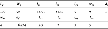
The geometry of the proposed MIMO antenna is given in Fig. 1 and its physical parameters are tabulated in Table 1. The antenna consists of two symmetrical radiating elements which are printed on the corners of mobile circuit board of size 50 × 100 mm2 with dielectric permittivity of 4.4 (FR4) and thickness of 1.6 mm. As seen from Fig. 1, the radiating element is constituted by binding four meandered radiating branches with a strip-line fed by a probe and they are mounted to be orthogonal in order to decrease the correlation between them. The resonant frequencies of these monopole branches are given in Table 2. Thanks to the simultaneously operation of these branches, a wide impedance bandwidth of the entire MIMO antenna is achieved. Since the antenna elements are orthogonally placed, the corners of the ground plane under the radiating element are triangularly trimmed in order to get the better impedance matching. Despite the fact that the antenna design in this form could satisfy the isolation requirements for MIMO operation, nevertheless, a plus-shaped structure at the ground plane is designed to achieve better isolation level between the two input ports. Hence, a large operating frequency band of 1.8–4.0 GHz is achieved for the MIMO antenna as seen in Fig. 3.
Geometry of proposed MIMO antenna: (a) perspective view, (b) elaborate view with ground dimensions, (c) detailed view of Antenna 1.

Physical parameters (mm) of the proposed antenna design.

Resonant frequencies of monopole branches.

The simulations are carried out by means of electromagnetic packed software called IE3D™ to design the proposed MIMO antenna. In simulations, the radiating elements are assumed to be 50 Ω probe feed with 1 V wave source and the cell per wavelength ratio is set to be 25 in the limit of 5 GHz. The simulations are performed over the frequency range from 1 to 5 GHz for 201 discrete frequency points.
The geometry of the antenna has a crucial impact on the MIMO performance. Especially, the ground plane plays a key role to enhance the impedance bandwidth and the isolation between radiating elements since they share the same surface currents distribution. To investigate these effects, four different geometric forms of ground plane are given in Fig. 2 and their corresponding s-parameters plots are illustrated in Fig. 3. It is clearly seen that the impedance bandwidth can be effectively improved by properly cutting the ground plane under the radiating branches. s 11 parameter is remarkably increased (approximately 20 dB) by triangularly trimming the corner of the ground plane. In fact, it provides sufficient isolated radiating elements (s 12≈ –10 dB) for MIMO operations due to being orthogonal to each other. A plus-shaped structure is inserted into the ground plane between two radiating elements to further enhance the isolation. Therefore, a reduction of about 10 dB in mutual coupling is achieved over the operating band as seen in Fig. 3.
The MIMO antenna for different geometric forms of ground plane: (a) FORM1, (b) FORM2, (c) FORM3, (d) FORM4.
The simulated s-parameters of the MIMO antenna for different geometric forms of ground plane.
III. FABRICATION OF THE MIMO ANTENNA
A prototype of the MIMO antenna design is realized according to physical parameters given in Table 1. As seen in Fig. 4, the antenna elements and ground plane are printed on the PCB material of FR4 having a thickness of 1.6 mm and substrate dielectric permittivity of 4.4 with tangent loss of 0.017. The antenna elements are fed through 50 Ω SMAs. The s-parameters of the proposed antenna are measured by means of Agilent Technologies N5230A PNA–L RF network analyzer. The simulated and measured s-parameter plots are presented in Fig. 5. It is seen that the measured s-parameters satisfy most of the LTE, WiMAX, and WLAN bands as listed in Table 3. Note that the discrepancies between the simulated and measured plots may be attributed to the variations in geometry, permittivity, and thicknesses of substrate and copper cladding, and mismatch of probe feed in the fabrication process. The prototyped MIMO antenna operates over frequency range of 1.8–5.0 GHz with minimum isolation of – 13 dB and its isolation is less than – 20 dB for the range of 2.4–5.0 GHz, as well.
Illustration of the prototyped MIMO antenna: (a) front view, (b) back view.
Simulated ( s 11,
 s 12) and measured (
 s 11,
 s 12) s-parameters of prototyped MIMO antenna.
The supported operating bands (in GHz) of LTE, WiMAX, and WLAN standards by the proposed MIMO antenna.

A) Radiation Pattern
Fig. 6 shows the measured radiation pattern of the proposed MIMO antenna for frequencies of 1.9, 3.17, and 3.65 GHz when Port 1 is excited. The peak gains of 2.65, 4.62, and 4.50 dBi occur at the frequency of 1.9, 3.17, and 3.65 GHz, respectively. The radiation patterns are similar to each other for three frequency points. The patterns for the xz- and yz-planes are omni-directional except for 90° and 270° because of the ground plane layouts on the xy-plane.
Measured radiation pattern (dBi) when Port 1 is excited: (a) E θ in the xz-plane (b) E θ in the yz-plane (c) E φ in the xy-plane ( 1.9 GHz,
 3.17 GHz,
 3.65 GHz).
B) Surface Current Distribution
In order to inspect the underlying current mechanism of the antenna design, simulated surface current distributions at distinct frequencies of 1.9, 3.17, and 3.65 GHz for Port-1 excitation are given in Fig. 7. Peak surface currents of 85.8, 86.84, and 56.4 A/m are obtained at the frequencies of 1.9, 3.17, and 3.65 GHz, respectively. It is observed that the majority of the electric current is concentrated at the radiating branches and the triangular corners of the ground plane. This situation implies that electric field lines occur between these parts of the antenna. Since the antenna elements are orthogonal to each other and parasitic element collects on itself most of the jumping current, less current leaks to the adjacent Antenna-2.
Surface current distributions for Port 1 excitation: (a) 1.9 GHz, (b) 3.17 GHz, (c) 3.65 GHz.
C) Gain and Envelope Correlation Coefficient (ECC)
The measured peak gain versus frequency is plotted in Fig. 8. The peak gain varies over 3 dBi across the operating band, while the peak gain occurs as 4.56 dBi in the vicinity of 3.2 GHz. Fig. 8 also contains ECC, which is an important parameter to appreciate the diversity characteristics of a MIMO system. It is obtained from the radiation pattern defined by IE3D™. The lower the ECC level, in general, the higher the diversity. As seen in Fig. 8, the ECC maintains <0.1 over the entire operating band means that the antenna design has good diversity.
Variation of measured gain and simulated ECC versus frequency.
D) Total Active Reflection Coefficient (TARC)
TARC which accounts for both coupling and random signal combination of N port MIMO system, which can be defined as the ratio of the square root of total reflected power divided by the square root of total incident power [Reference Mallahzadeh, Es'haghi and Alipour4] as follows:
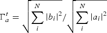 $$\Gamma _a^t={{\sqrt {\sum\limits_i^N {\left\vert {b_i } \right\vert } ^2 } } / {\sqrt {\sum\limits_i^N {\left\vert {a_i } \right\vert } ^2 } }}$$
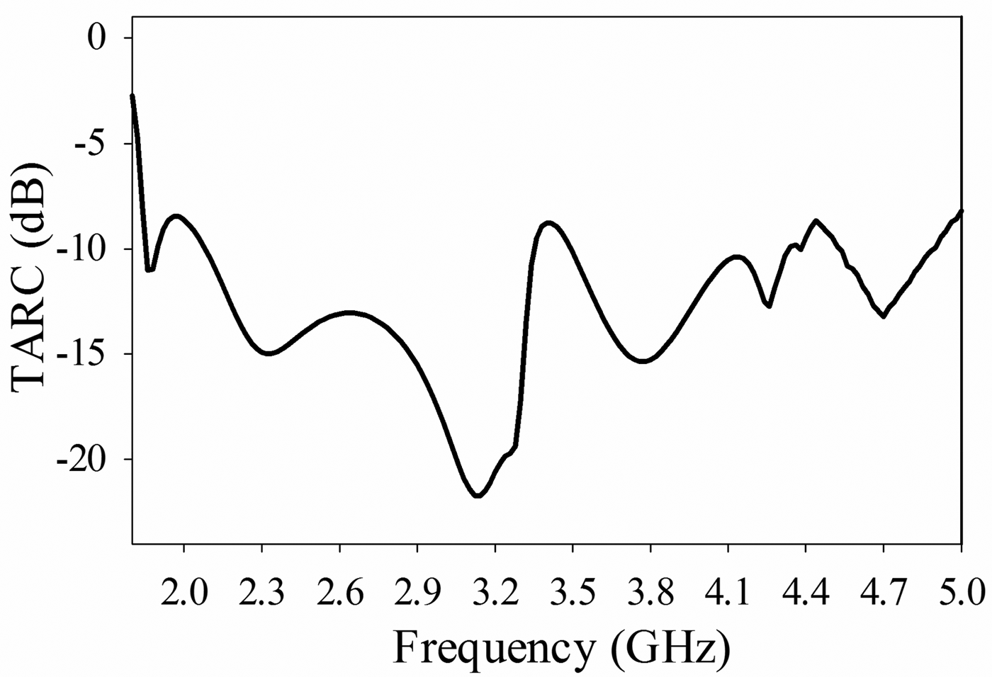
where a i is the incident signal vector with randomly phased elements and b i is the reflected signal vector. TARC versus frequency plot obtained by measurement for the proposed MIMO antenna is illustrated in Fig. 9. As seen, TARC maintains less than – 10 dB along the operating band.
Measured TARC plot versus frequency for the MIMO antenna.
It is evident that our MIMO antenna design has a lot of superiorities in accordance with the presented physical and performance characteristics such as being small and compact, having high isolation, wideband, high gain and good radiation, ECC, TARC over the others reported elsewhere. Therefore, it can be used in LTE, WiMAX, and WLAN mobile handsets.
IV. CONCLUSION
In this study, a compact wideband MIMO antenna is designed for the mobile handsets. The antenna is suitable for most bands of the LTE, WiMAX, and WLAN corresponding to the frequency range of 1.8–4.0 GHz. The antenna structure is consists of two symmetrical and orthogonally placed radiating elements with four meandered monopole branches and a plus-shaped parasitic element for achieving good isolation between the input ports. The performance of the antenna is investigated by simulation and then verified through the measurement. The antenna shows nearly omni-directional radiation behavior, good gain, ECC, and TARC variation and promises an excellent diversity performance for MIMO operation. Finally, the design of MIMO antenna for LTE, WiMAX, and WLAN enabled mobile handsets is proposed in this work with superior characteristics such as small in size, wideband, low correlation, good radiation pattern, and high gains.
ACKNOWLEDGEMENTS
This work is supported by the Scientific Research Fund Department of Mersin University under grant no: BAP-FBE EEMB (AT) 2013-4 DR. The authors are thankful to Mr. Mustafa Tekbas for his valuable help and contributions during the experiments in TUBITAK Marmara Research Center (MRC).
Ali Akdagli obtained the B.Sc., M.Sc., and Ph.D. degrees from Erciyes University, Kayseri, in 1995, 1997 and 2002, respectively, all in the Electronic Engineering. From 2003 to 2006 he was an Assistant Professor in the Electronic Engineering Department at Erciyes University. He joined the same department at Mersin University, where he currently works as a Professor. He has published more than 90 papers in journals and conference proceedings. His current research interests include evolutionary optimization techniques (genetic algorithm, ant colony optimization, differential evolution, particle swarm optimization, and artificial bee colony algorithms), artificial neural networks, and their applications to electromagnetic, wireless communication systems, microwave circuits, microstrip antennas, and antenna pattern synthesis problems. Dr. Akdagli is an editorial board member of ‘Recent Patents on Electrical Engineering’, ‘International Journal of Computers’, and Journal of ‘Computational Engineering’.
Abdurrahim Toktas was born in 1977. He received his B.Sc. degree in Electrical and Electronics Engineering from Gaziantep University, Turkey in 2002. He worked as telecom expert from 2003 to 2010 for Turk Telecom Company which is the national PSTN and wideband internet operator. He obtained his M.Sc. and Ph.D. degrees in Electrical and Electronics Engineering from Mersin University, Turkey, in 2010 and 2014, respectively. He has been working in IT Department of Mersin University since 2010. His current research interests include electromagnetics, antennas, MIMO antennas, computational electromagnetic, artificial intelligent, evolutionary optimization algorithms, and their applications electromagnetics, microwave circuits, and wireless communication systems.