
Introduction
Electroplating is an indispensable film formation process in a wide area of engineering. It has been utilized for enhancing the performance, extending the lifetimes, and improving the appearance of materials. Similarly, electroless plating is useful for forming metal thin films on insulating substrates. In spite of their technical importance, both the electro- and electroless-plating methods involve fundamental problems. The inclusion of pinholes in the films is one of the most persistent problems. A pinhole is formed when a hydrogen bubble, which is generated by a side reaction of reducing metal ions, stays on the substrate surface and blocks the film growth in that spot.[ Reference Tsai, Hsu, Hwu, Chen, Chang, Je, Lin, Groso and Margaritondo 1 , Reference Hsu, Seol, Lo, Liu, Wang, Lin, Hwu, Chen, Chang, Je and Margaritondo 2 ] A conventional method for preventing the formation of pinholes is to agitate the plating solution, thereby removing the hydrogen bubbles from the surface. However, small bubbles tend to adhere strongly to the surface owing to surface tension and are not detached easily by buoyancy or by the drag force of the plating liquid.[ Reference Vogt and Balzer 3 , Reference Balzer and Vogt 4 ] Pinholes cause critical damage to the corrosion resistance of coatings. For example, nickel deposits are known to have a barrier function that protects the substrate without a sacrificial effect. However, a film thickness of at least 10 µm, and preferably 30 µm, is required to avoid the effects of pinholes and achieve practical corrosion resistance.[ Reference Bari, Cotell, Sprague and Smidt 5 ] The ability to reduce the minimum thickness while still attaining corrosion resistance would be a significant achievement.
Meanwhile, recent studies have revealed the possibility of resolving the pinhole issues by using unconventional plating media. Yoshida et al. proposed a new electroplating technique that performs film deposition in an emulsion consisting of supercritical carbon dioxide and a plating solution.[ Reference Yoshida, Sone, Mizushima, Yan, Wakabayashi, Abe, Tao, Ichihara and Miyata 6 , Reference Yoshida, Sone, Wakabayashi, Abe, Tao, Yan, Ichihara and Miyata 7 ] They achieved a notable reduction in the number of pinholes in nickel films with this method.[ Reference Yan, Sone, Sato, Ichihara and Miyata 8 ] On the other hand, Yamada et al. developed a technique for achieving electroplating in a foam of electrolyte that was generated by bubbling nitrogen gas into a plating solution at atmospheric pressure.[ Reference Yamada, Mitsuya, Furuhashi, Ichihara and Usui 9 ] They found that the foam can remove hydrogen bubbles efficiently by merging with them or by repelling them from the surface.[ Reference Yamada, Fujisawa, Sugawara, Furuhashi, Ichihara and Usui 10 ] As a consequence, the nickel films deposited in the foam had smaller numbers of pinholes and showed superior corrosion resistance compared with films deposited in the conventional liquid.[ Reference Yamada, Fujisawa, Sugawara, Furuhashi, Ichihara and Usui 11 ] This method has advantages in terms of simplicity of the apparatus and ease of operation at atmospheric pressure. Another possible advantage of using foam is a modification of fluid dynamics on the substrate surface. It is reported that the turbulent skin friction on a surface can be reduced by introducing microbubbles into the liquid.[ Reference Madavan, Deutsch and Merkle 12 ] It is thought that the microbubbles increase the apparent viscosity of the liquid, reducing the Reynolds stress and turbulence in the boundary layer.[ Reference Kato, Fujii, Yamaguchi and Miyanaga 13 ] Although such an effect is not pronounced for bubbles with a diameter larger than 0.5 mm,[ Reference Kawamura, Moriguchi, Kato, Kakugawa and Kodama 14 ] one cannot deny the possibility that the foam provides a flow field, which is different from the conventional liquid.
In our previous work, we explored the possibility of achieving electroless plating in a foam of electrolyte in place of the conventional liquid.[ Reference Furuhashi, Yamada, Ichihara, Takai and Usui 15 ] Although the film growth rate was considerably lower in foam than in liquid, film deposition was possible when there was a flow of foam on the surface of the substrate. However, the effect of foam plating on pinholes and corrosion resistance was not explored in our previous work. In further pursuit of this new electroless deposition technique, this paper describes our recent experimental results from depositing electroless nickel films in electrolyte foam. In this work, a ferroxyl indicator test was utilized to estimate the effect of the foam on the corrosion resistance of the films.
Experiment
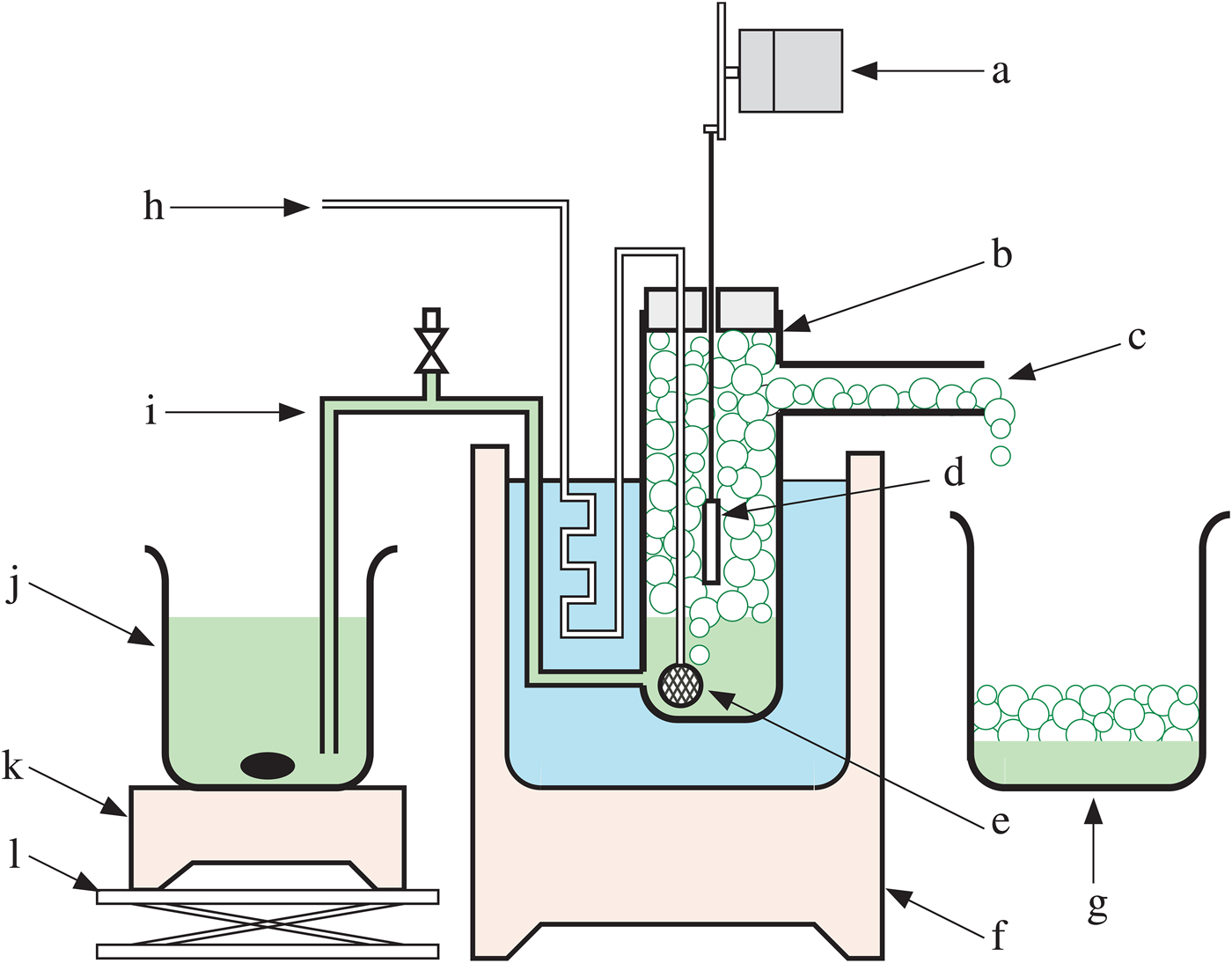
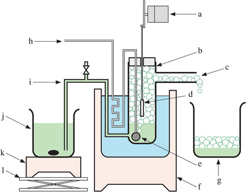
The electrolyte foam was generated from a commercial hypophosphite-based solution for electroless nickel plating (Okuno Chemical Industries, Top Nicoron F-153) to which was added sulfuric acid monododecyl ester sodium salt (SDS) as a surfactant. Figure 1 shows a schematic diagram of the electroless foam plating system, which consists of a solution reservoir, a plating vessel, and a receiving vessel. The solution reservoir is a glass beaker filled with 1 L of the plating solution with 0.1 wt.% of SDS added to it. The reservoir was heated to 85 °C on a hot stirrer. The plating vessel was a glass cylinder with an inner diameter of 8 cm and a height of 30 cm. The plating solution was transferred from the solution reservoir to the plating vessel via a siphon. The liquid level in the plating vessel was maintained at a depth of 9.5 cm by adjusting the height of the solution reservoir. Nitrogen gas was introduced into the bottom of the plating vessel through a spherical glass filter 4 cm in diameter with a mesh size of 40 µm. The plating vessel was heated to 85 °C in a water bath. The nitrogen gas was also preheated by passing it through the water bath before it flowed into the glass filter. The nitrogen flow rate was varied in the range of 0.2–1 L/min. After a few minutes of introducing the nitrogen gas, the foam of electroplating liquid filled up the plating vessel and overflowed into the receiving vessel, generating a steady flow of the foam inside the plating vessel. The flow speed of the foam in the plating vessel was 20 cm/min when the nitrogen flow rate was 1 L/min.
Schematic diagram of the system for electroless plating in a foam of plating solution. (a) Substrate rocker, (b) plating vessel, (c) drain, (d) substrate, €(e) glass filter, (f) water bath, (g) receiving vessel, (h) nitrogen gas inlet, (i) siphon, (j) solution reservoir, (k) hot stirrer, (l) jack.

The substrate was a 2.5 × 4 cm2 iron test piece (Yamamoto-MS, B-51). Its center was placed 5 cm above the liquid level, and it was rocked in the vertical direction with a stroke of 2.5 cm at 30 cycles/min. The commercially obtained substrate had been precoated with a zinc protective layer, which was removed by immersing the substrate into a 7% aqueous solution of hydrochloric acid followed by rinsing with pure water just before the film deposition. For comparison, films were also deposited in the liquid without generating foam. In this case, deposition was achieved in a beaker on a hot magnetic stirrer using the same liquid (added with SDS) at the same temperature as stated above.
For characterization, 2-μm-thick films were deposited either in the liquid or in the foam generated with different nitrogen flow rates. The film thickness was measured with a fluorescence measuring system (Fischer Instruments XDL-B). Surface morphology of the film was observed with a scanning electron microscope (SEM, Hitachi S-3700N). Crystallographic property of the film was characterized with a x-ray diffractometer (Rigaku SmartLab, with Cu target) using focusing optics with a θ–2θ scan. The concentration of phosphorus in the film was analyzed with an electron probe microanalyzer (EPMA, JEOL JXA-8900M). Corrosion resistance of the film was examined by the ferroxyl indicator test according to the procedure of ASTM B 689. A filter paper was soaked in an aqueous solution consisting of 10 g/L potassium hexacyanoferrate (II) trihydrate, 10 g/L potassium hexacyanoferrate (III), and 60 g/L sodium chloride. This filter paper was attached to the surface of the specimen for 5 min. The corrosion spots that appeared on the filter paper were recorded with a digital camera, and the image was binarized to obtain the area fraction of corrosion.
Results and discussion
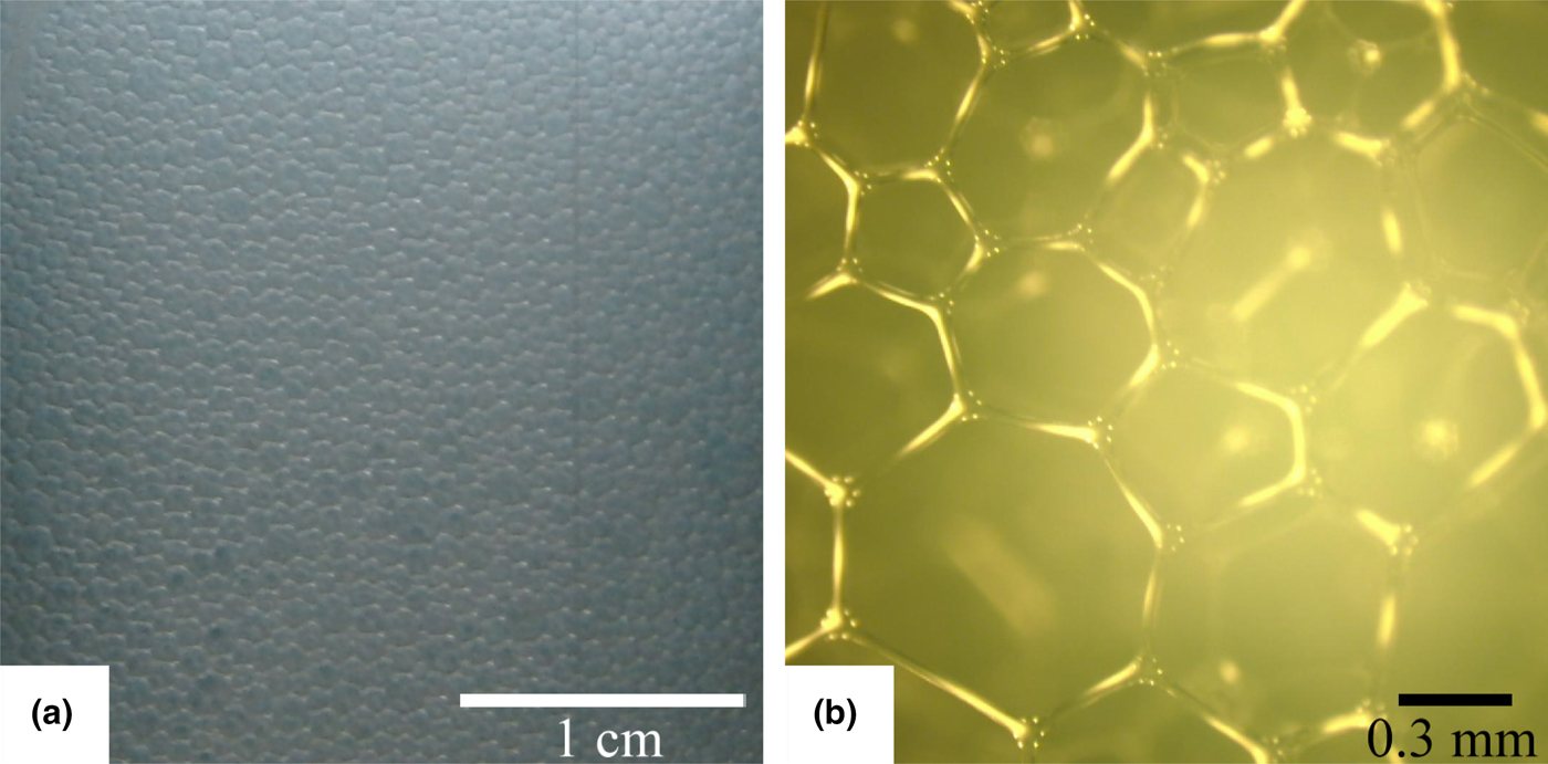
Figure 2(a) shows a photograph of the foam generated by the apparatus shown in Fig. 1 observed through the wall of the plating vessel. An optical micrograph of the foam that was sampled from the overflow is also shown in Fig. 2(b). This foam was generated with a nitrogen flow rate of 0.5 L/min. It was observed that the foam consisted of polyhedral gas cells separated by thin liquid lamellae. The average diameter of the foam obtained from the image (b) was 0.48 mm. The foam diameter was not influenced significantly by the nitrogen flow rate. In our previous work on electroplating in foam, the foam diameter was varied by changing the concentration of surfactant[ Reference Yamada, Mitsuya, Furuhashi, Ichihara and Usui 9 ] or by exerting a shearing force on the foam with a rotating disk.[ Reference Yamada, Sugawara, Furuhashi, Ichihara and Usui 16 ] The foam diameter was found to influence film characteristics such as the size of crystallites. However, this work is presently not focusing on the effect of foam diameter on electroless plating. Figure 2 reveals that the foam used in this system is largely different from the bubbles that are frequently used for stirring the liquid in the conventional plating technique. The conventional bubbles are spherical gas cells individually floating in the bulk of the liquid. The foam used in our system has a considerably smaller liquid/gas ratio compared with the bubbled plating liquid.
(a) A photograph of the foam observed through the wall of the plating vessel and (b) an optical micrograph of the foam that was sampled from the overflow.
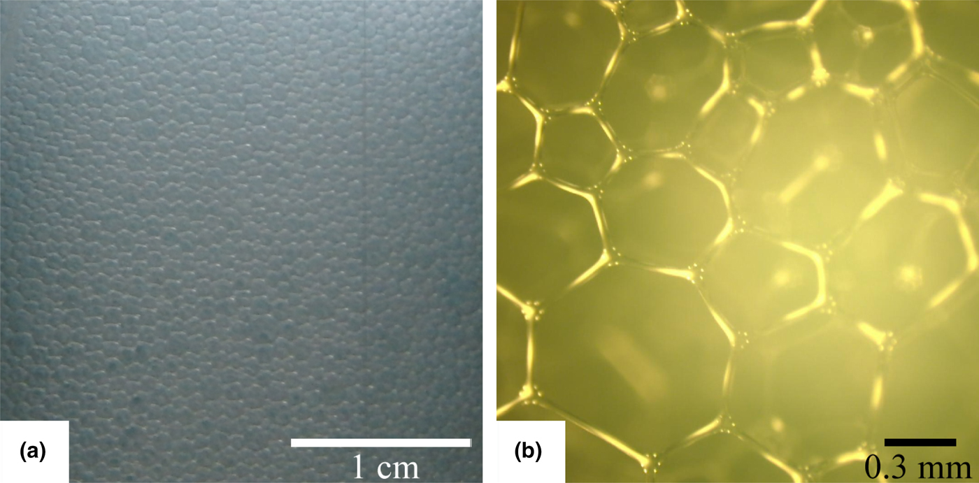
Figure 2 suggests that ion paths in the foam are limited to the thin liquid lamellae and the Plateau borders between the gas cells.[ Reference Wilde 17 ] This limitation resulted in an insufficient ion supply when the plating was performed in the foam. As a consequence, when the electroless plating was achieved in stationary foam, the film growth rate was very low and the deposited film showed a gray and opaque appearance. However, film growth was notably improved by generating a flow of foam by feeding nitrogen gas, thereby physically assisting the ion transportation. The film growth rate was only 0.9 µm/h at a nitrogen flow rate of 0.2 L/min, however, it increased almost linearly with an increasing nitrogen flow rate, reaching 4.4 µm/h at a nitrogen flow rate of 1 L/min. When electroless plating was performed in the conventional liquid, the film growth rate was 12.3 µm/h, which is in good accordance with the technical information from the supplier of the plating solution.[ 18 ] The maximum film growth rate that can be attained in foam appears to depend on the control of the foam flow. With the current experimental setup, the flow of foam became inhomogeneous when the nitrogen flow rate exceeded 1 L/min. At such a high flow rate, the bent flow geometry of the foam in the plating vessel, which had a necked branch for the drain, induced turbulence in the flow, resulting in the inhomogeneous film. When the nitrogen flow rate exceeded 1 L/min, the foam came to include air slag in the form of large bubbles, which also hindered uniform coverage of the substrate by the foam.
Uniform and specular films with thickness 2 µm were deposited in foam generated with nitrogen flow rates of 0.4–1 L/min as well as in the conventional liquid. With a nitrogen flow rate of 0.2 L/min, the film growth rate was not high enough to obtain a film thickness of 2 µm. With the film thicknesses of 2 µm, the polish-scratches on the original substrate were still visible on the film surface when observed with an optical microscope. However, no pinhole defects were observed in the films deposited in foam. On the other hand, the film deposited in liquid showed several defects that can be attributed to pinholes. It is thought that the foam contributes to removing hydrogen bubbles from the substrate surface through the same mechanism that was observed in our previous work on electrodeposition in electrolyte foam.[ Reference Kato, Fujii, Yamaguchi and Miyanaga 13 ]
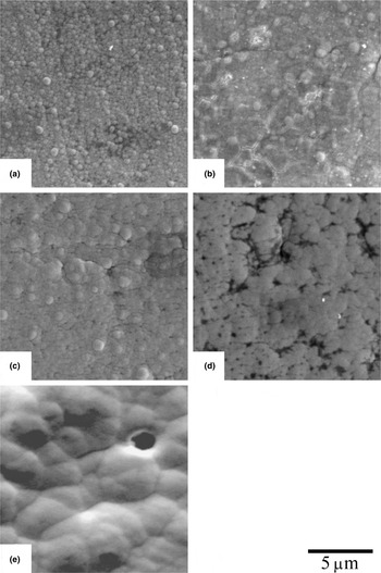
Figure 3 shows SEM images of the films deposited in foam generated with nitrogen flow rates of (a) 0.4 L/min, (b) 0.6 L/min, (c) 0.8 L/min, and (d) 1.0 L/min. The images were taken at a position around the center of the substrates. An SEM image of the film deposited in liquid at a position around a pinhole is shown in (e). No pinholes were observed in the films deposited in foam. It is inevitable that the film deposited in liquid includes pinholes considering that the thickness is only 2 µm. The number of pinholes is known to be reduced by vigorous stirring even with conventional electroless plating in liquid. The flow speed of the liquid when preparing the film shown in Fig. 3(e) was about 45 cm/min, which is much faster than the flow speed of foam employed in this work. Therefore, the results are shown in Fig. 3 indicate that the films deposited in foam have a significantly smaller number of pinholes compared with the film deposited in the liquid at least under comparable conditions. The film deposited in the foam generated with a nitrogen flow rate of 0.4 L/m showed granular features. The surface smoothness was improved by increasing the nitrogen flow rate to 0.6–0.8 L/min. At the nitrogen flow rate of 1.0 L/min, irregularity appeared in the film morphology. It is possible that this morphological irregularity was induced because the flow of foam became nonuniform at the nitrogen flow rate of 1.0 L/min.
SEM images of nickel films deposited in foam generated with nitrogen flow rates of (a) 0.4 L/min, (b) 0.6 L/min, (c) 0.8 L/min, and (d) 1.0 L/min. Image (e) shows a film deposited in liquid.

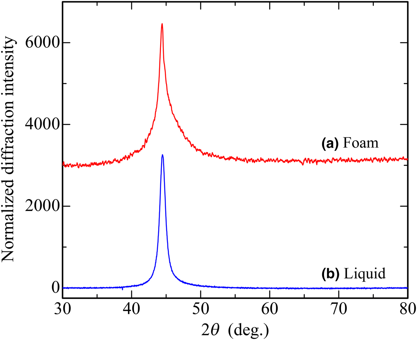
Figure 4 shows the wide-angle x-ray diffraction patterns of the films deposited in foam (a) and in liquid (b). The foam was generated with a nitrogen flow rate of 0.8 L/min. With the other nitrogen flow rates, almost the same diffraction patterns were obtained as a pattern (a). Both films showed a single diffraction peak at 44.7°, which corresponds to the (111) plane of nickel crystal. Other planes such as (200) at 51.9° and (220) at 76.4° were not observed. This result indicates that these films have preferential crystal orientation with the (111) plane parallel to the substrate surface. It is notable that the film deposited in foam had a broad diffraction peak with an integral half-width of 3.2°, while the film deposited in liquid showed a sharp diffraction peak with an integral half-width of 1.6°. The crystallite size calculated by the Scherrer equation (assuming a Scherrer constant of 0.94) was 1.9 nm for the film deposited in foam, and 3.6 nm for the film deposited in liquid. Reduction of crystallite size has also been reported with electroplating in foam[ Reference Furuhashi, Yamada, Ichihara, Takai and Usui 15 ] and in emulsion with supercritical carbon dioxide.[ Reference Wakabayashi, Sato, Sone, Takada, Yan, Abe, Mizumoto, Ichihara and Miyata 19 ] It is thought that continuous growth of crystallites is suppressed owing to discontinuous film deposition in the foam and the emulsion.
x-ray diffraction patterns of nickel films deposited (a) in foam generated with nitrogen flow rates of 0.8 L/min and (b) in liquid. The ordinate has been normalized for ease of comparison.

Another factor that can influence the crystallite size is the phosphorus content of the film. Electroless nickel films deposited in a hypophosphite-based solution are known to contain a certain amount of phosphorus, which reduces the crystallinity of the nickel.[ Reference Allen and VanderSande 20 , Reference Kumar and Nair 21 ] EPMA measurement showed that the atomic concentration of phosphorus in the film deposited in foam was about 6.6%, while that in the film deposited in the liquid was 4.4%. The phosphorus concentration did not have an explicit dependence on the nitrogen flow rate. The reason why the film deposited in foam had a higher phosphorus concentration is not clear at this point. However, the larger amount of phosphorus could also lead to the broadening of the x-ray diffraction peak when the film was deposited in foam. The reduction of grain size is advantageous for improving the surface smoothness, glossiness, and mechanical strength of the film.[ Reference Yamada, Sugawara, Furuhashi, Ichihara and Usui 22 ]
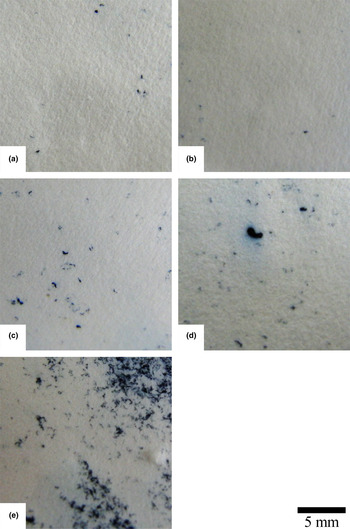
One of the important characteristics of nickel plating is its corrosion resistance. Figure 5 shows the corrosion spots observed on the surface of the indicator papers in the ferroxyl test for the 2-μm thick films deposited in foam (a–d) and in liquid (e). These images cover almost the entire areas of the substrates except the perimeters where films frequently show irregular growth such as nonuniform film thickness. In general, a film thickness of at least 10 µm is required to achieve practical corrosion resistance by nickel plating.[ Reference Tomlinson and Carroll 23 , Reference Hsu, Chiu and Shih 24 ] Owing to the small thickness in this experiment, the film deposited in liquid suffered severe corrosion as shown in Fig. 5(e). On the other hand, the films deposited in foam showed remarkable corrosion resistance compared to the film deposited in liquid even with this small film thickness. The fraction of the corroded area, obtained by binarizing the images in Fig. 5, was 20% for the film deposited in liquid, while the films deposited in foam had corroded areas that were smaller than 1%. In particular, the film deposited in foam generated with a nitrogen flow rate of 0.6 L/min had a corroded area as small as 0.1%. It is thought that the improvement of corrosion resistance reflects the reduction of pinhole density, owing to the removal of hydrogen bubbles from the substrate surface when the film is deposited in foam.
Corrosion spots on the filter papers of the ferroxyl indicator test for the films deposited in foams generated with nitrogen flow rates of (a) 0.4 L/min, (b) 0.6 L/min, (c) 0.8 L/min, and (d) 1.0 L/min. Image (e) shows the corrosion spots of the film deposited in liquid.

Conclusion
Electroless plating of nickel thin films was achieved in a foam of plating solution in place of the conventional liquid. The film growth rate was considerably lower in foam than in liquid owing to the limited paths for ion transportation. However, the film growth rate improved with increasing flow rates of nitrogen gas, i.e., with increasing flow speeds of the foam. Although the film growth rate was only 36% of the value expected in conventional liquid, further improvement by increasing the flow speed is expected. For this purpose, a plating vessel that allows smooth flow of foam without turbulence is required. It is also expected that the growth rate can be increased by modifying the characteristics of the foam such as the bubble diameter and the fraction of liquid. These modifications are to be explored in our future work. Since electroless plating is mainly used for preparing very thin seed layers before accumulating thick electroplated layers on insulating substrates, the low film growth rate in foam may not be a serious problem. The film deposited in foam had a smooth surface morphology without pinholes. In addition, the film deposited in foam had smaller crystallite size than that deposited in liquid. This is presumably due to the discontinuous film growth and the higher phosphorus concentration in the film when deposited in foam.
The most significant effect of electroless deposition in foam was the remarkable improvement in corrosion resistance. Even with a film thickness of 2 µm, the film deposited in foam showed a fraction of the corroded area of only 0.1% at the ferroxyl indicator test. The superior corrosion resistance reflects the pinhole-free film morphology. The reduction of crystallite size can also lead to uniform coverage of the film on the substrate surface even at a small film thickness. These features suggest that electroless deposition in foam is advantageous for preparing thin films with smooth surfaces, high physical robustness, and high chemical stability.
Acknowledgments
The authors acknowledge the Japan Society for the Promotion of Science for KAKENHI Grant number JP21656204. They also acknowledge the Japan Science and Technology Agency for support with Adaptable and Seamless Technology Transfer Program number AS242Z02308K.