1. Introduction
Wireless capsule endoscope (WCE) is particularly useful to reach inaccessible regions with minimal patient discomfort precluded to standard probe endoscopy [Reference Park, Cho and Ji1, Reference Iddan, Meron, Glukhovsky and Swain2]. To address the limitation of exploiting peristalsis to move passively along the gastrointestinal (GI) tract, several WCEs integrating the locomotion mechanisms have been developed to implement active propulsion, such as inchworm-like type [Reference Gao and Yan3], clamper type [Reference Gao, Yan, He, Xu and Wang4], and propeller type [Reference De Falco, Tortora, Dario and Menciassi5]. However, most of them could not be long-time wirelessly actuated. The magnetic navigation, exploiting the external magnetic fields to realize remote control on the medical robotics, has solved power supply issue and been proven to be impactful in many applications: macroscopically, the magnetic navigated capsule endoscope (MNCE) is one of the possible applications capable of assisting in the diagnosis [Reference Hale, Rahman, Drew, Sidhu, Riley, Patel and McAlindon6]; microscopically, the micro-particles can be steered to the target in blood vessels by magnetic field [Reference Chao, Yu, Dai, Xu, Zhang, Wang and Jin7, Reference Chen, Hoop, Mushtaq, Siringil, Hu, Nelson and Pane8]. Nevertheless, for therapeutic procedures such as biopsy [Reference Son, Gilbert and Sitti9] and localized drug delivery [Reference Munoz, Alici, Zhou, Li and Sitti10], precise fix-point posture adjustment of the MNCE is still a challenge in some spacious spots, such as esophagus, stomach, and colon.
A typical manipulation system is the external permanent magnet (EPM) system, which generates a gradient magnetic field to apply static magnetic force, employing static balance control to adjust the posture of the MNCE [Reference Norton, Slawinski, Lay, Martin, Cox, Cummins, Desmulliez, Clutton, Obstein, Cochran and Valdastri11–Reference Taddese, Slawinski, Pirotta, De Momi, Obstein and Valdastri15]. Norton [Reference Norton, Slawinski, Lay, Martin, Cox, Cummins, Desmulliez, Clutton, Obstein, Cochran and Valdastri11] and Valdastri [Reference Ciuti, Valdastri, Menciassi and Dario12] proposed a robot arm with the EPM attached to the end effector to move the MNCE and conducted the magnetic levitation in the GI tract [Reference Pittiglio, Barducci, Martin, Norton, Avizzano, Obstein and Valdastri13]. However, for the MNCE with single rigid body structure, the EPM system has controllability limitations caused by the one-directional magnetic force: First, the distance between the EPM and MNCE will exponentially influence the force to magnetic navigation [Reference Ching, Hale and McAlindon14], and static balance is easily disturbed. Second, unique posture control is not available in the singular plane, which is the interface of two magnetic poles of the magnet [Reference Taddese, Slawinski, Pirotta, De Momi, Obstein and Valdastri15]. Third, due to the coupling of the magnetic force and magnetic moment in the gradient magnetic field, the posture alignment and the locomotion interfere with each other, resulting in the precise posture adjustment that is not always possible.
Lee [Reference Lee, Choi, Go, Jeong, Young Ko, Park and Park16] proposed an electromagnetic actuation (EMA) system (ALICE system) with five pairs of solenoid components, realizing to control posture alignment and locomotion, respectively. The average alignment angle error was about 3.84°. It is no doubt that EMA system has higher controllability than the EPM system, because the orientation and strength of the magnetic field can be adjusted accurately by digital control. However, essentially, the posture alignment still utilizes static balance control in ALICE system. In fact, clinically, the efficiency of static posture alignment is quite low, since doctors have to gradually reach the anticipated orientation through several trials even by the aid of the buoyancy in a water filled stomach [Reference Rey, Ogata, Hosoe, Ohtsuka, Ogata, Ikeda, Aihara, Pangtay, Hibi, Kudo and Tajiri17].
Fortunately, the magnetic navigated dual hemisphere capsule robot (DHCR) system can realize the fix-point posture adjustment [Reference Zhang, Liu, Liu, Ji, Yang and Liu18], which employs dynamic balance control, possessing the advantage of the higher accuracy and efficiency compared with the static balance control. In terms of manipulation system, the three-axis orthogonal square Helmholtz coils [Reference Zhang, Wang, Du, Sun and Wang19] can generate the spatial universal rotating magnetic vector (SURMV). Compared with the iron-core coils that will generate the magnetic field distortions, Helmholtz coils, as air-core coils, are relatively easy to control [Reference Schuerle, Erni, Flink, Kratochvil and Nelson20] and provide more uniform and precious magnetic field [Reference Alamgir, Fang, Gu and Han21] based on the superposition theorem. Structurally, the DHCR includes the active and passive hemispheres. The active hemisphere can rotate under the actuation of the SURMV, while the passive hemisphere is underactuated, subtly realizing the separation of the posture adjustment and locomotion based on tracking effect [Reference Zhang, Liu, Liu, Ji, Yang and Liu18]-the DHCR’s axis keeps tracking the normal orientation of the SURMV.
During the dynamic posture adjustment, the magnetic flux density, and the angular velocity of the rotating magnetic vector, along with the damping coefficient of the surface have a great influence on the stability of dynamic posture control. In order to control the posture accurately by adjusting above parameters, mathematic models and analysis have been carried out. Hoang et al. [Reference Hoang, Nguyen, Le, Kim, Choi, Kang, Park and Kim22] and Sun et al. [Reference Sun, Liu, Wang, Niu and Wang23] listed the simple formulas of the magnetic force and torque and verified the tracking error with experiments. However, system stability is not studied, and the effects of each parameter have never been clarified and presented clearly.
In this paper, based on the gyroscope principle [Reference Aslanov and Yudintsev24], the dynamic modeling of the DHCR with decoupled control variables is established. Since the dynamic modeling has complex nonlinear characteristics, in terms of the high-order coupling nonlinear time-varying oscillators, and the external torque has an obvious effect on the posture response of the DHCR, the stability domains of the parameters are obtained, and the influences of factors on stability are discussed and analyzed in detail. In order to improve tracking performance of the DHCR, sliding mode control method based on nominal model is employed to accurately control the posture of the DHCR. The experiments of motion stability and posture alignment performance are carried out, and the results indicate that the fix-point posture adjustment can be realized with higher accuracy and efficiency.
2. Working principle of the DHCR system
2.1. Structure of the DHCR
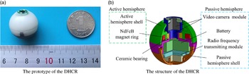
The prototype and the structure of the DHCR are shown in Fig. 1(a) and (b) respectively. The DHCR consists of an active hemisphere and a passive one. The active hemisphere includes the active hemispherical shell and the radially magnetized NdFeB magnet ring, while the passive hemisphere includes the passive hemispherical shell, the video camera module, the battery, and the radio frequency transmitting module. The active hemispherical shell and the passive one can be fabricated by additive manufacturing. The passive hemisphere is connected with the active hemisphere through the ceramic bearing, thus the active hemisphere can rotate around the passive hemisphere. The main structural parameters are shown in Table I.
The prototype and the structure of the DHCR.

2.2. Three-phase current superposition control
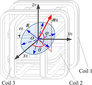
Based on the orthogonal superposition theorem of three alternating magnetic components [Reference Zhang, Wang, Du, Sun and Wang19], the SURMV is superimposed by separately applying tri-phase sine currents to three-axis orthogonal square Helmholtz coils and B are derived as [Reference Zhang, Yu, Yang, Huang and Chen25]
 \begin{equation} \boldsymbol{{B}}=\left(\begin{array}{l} B_{x}\\[5pt] B_{y}\\[5pt] B_{z} \end{array}\right)=\left(\begin{array}{l} B_{0}\sqrt{1-\cos ^{2}\theta \cos ^{2}\varphi }\cdot \sin \left(\omega t+\phi _{x}\pm \pi \right)\\[5pt] B_{0}\sqrt{1-\sin ^{2}\theta \cos ^{2}\varphi }\cdot \sin \left(\omega t-\phi _{y}\right)\\[5pt] B_{0}\cos \varphi \sin \left(\omega t\right) \end{array}\right) \end{equation}
where tan
 $\phi$
x = tanθ/sin
 $\varphi$
, tan
 $\phi$
y = cotθ/sin
 $\varphi$
; B
0 and
 $\omega$
are the magnetic flux density and angular velocity of the rotating magnetic vector, respectively; θ and
 $\varphi$
are the yaw angle and pitch angle of the normal vector
n
B of the rotating magnetic vector
B
, respectively, as shown in Fig. 2.
For the three-axis orthogonal square Helmholtz coils, the relationship of the rotating magnetic vector B and the control input current I can be expressed as follows:
 \begin{equation} \boldsymbol{{B}}=\boldsymbol{{KI}} \end{equation}
where K ∈R 3 × 3 is the mapping matrix in tesla per ampere from the current input to the magnetic vector
 \begin{equation} \boldsymbol{{K}}=\left(\begin{array}{c@{\quad}c@{\quad}c} K_{x} & 0 & 0\\[5pt] 0 & K_{y} & 0\\[5pt] 0 & 0 & K_{z} \end{array}\right) \end{equation}
where K i (i = x,y,z) are the structural parameters of each coil, respectively [Reference Alamgir, Fang, Gu and Han21, Reference Zhang, Chi and Su26].
Considering the different structural parameters of the three-axis square Helmholtz coils, it is necessary to compensate the control input currents for achieve the uniform magnetic vector. The modified basic triphase sin current equations are derived as
 \begin{equation} \boldsymbol{{I}}=\boldsymbol{{K}}^{-\mathrm{1}}\boldsymbol{{B}}=\left(\begin{array}{l} I_{x}\\[5pt] I_{y}\\[5pt] I_{z} \end{array}\right)=\left(\begin{array}{l} K_{\mathrm{z}}/K_{x}I_{0}\sqrt{1-\cos ^{2}\theta \cos ^{2}\varphi }\cdot \sin \left(\omega t+\phi _{x}\pm \pi \right)\\[5pt] K_{\mathrm{z}}/K_{y}I_{0}\sqrt{1-\sin ^{2}\theta \cos ^{2}\varphi }\cdot \sin \left(\omega t-\phi _{y}\right)\\[5pt] I_{0}\cos \varphi \sin \left(\omega t\right) \end{array}\right) \end{equation}
where K i (i = x,y,z) is the structural parameter of each coil, respectively. The magnetic flux density B 0 can be obtained from the control input current I 0, namely, B 0 = K z I 0.
The structure parameters of the DHCR.

The SURMV generated by the three-axis orthogonal square Helmholtz coils.

Once the desired control parameters (I
0,
 $\omega$
, θ and
 $\varphi$
) are input into the control system, the coils will generate a sufficient rotating magnetic vector
B
for posture alignment.
2.3. Manipulation based on tracking effect
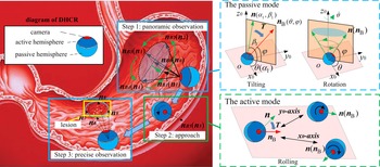
As shown in Fig 3, the magnetic torque T is coupled between the radially magnetized magnet ring and the rotating magnetic vector B , which drives the DHCR realizing three basic motions-rotation and tilting motions and 2-D rolling. Before the active hemisphere touches the intestine, the DHCR is in the passive mode for rotation or tilting, while the active hemisphere touches the intestine, the DHCR is in the active mode for rolling locomotion. Tracking effect can navigate the DHCR to convert from the passive mode to the active mode for the rolling locomotion and vice versa. For medical application scenario inside the stomach, as shown in Fig. 3, the detailed operation process is as follows:
The overall medical application scenario of the DHCR and the schemes of the DHCR motions.

Step 1: Posture adjustment in the passive mode can be used for panoramic observation to find the position of the lesion area briefly. First, the doctor applies a vertical upward normal vector
n
B0 to make the DHCR in a stable vertical upward with the axis
n
0. Then, the doctor can use a joystick to control the tilting motion with angle
 $\varphi$
, and the rotation motion around vertical z
0-axis with angle θ, for surrounding observation (
n
1 , n
2 , n
3 and
n
4). Based on the real-time video, the doctor can determine the position of the lesion area briefly by the image location.
Step 2: Rolling locomotion in the active mode can be used to approach the lesion area. In this case, the doctor attempts to apply the perpendicular normal vector n B5 with the propagation direction normal vector, and the DHCR realizes rolling locomotion in x 0 oy 0 plane along the propagation direction. Thus, the active hemisphere can drive the DHCR to reach the lesion area.
Step 3: Posture adjustment can be used for close observation and further medical treatments. Similar to step 1, the axis of the DHCR is navigated to the orientation n 6 , n 7 , n 8, and n 9. As a single-use product [Reference Van de Bruaene, De Looze and Hindryckx27], the DHCR is automatically excreted from the GI tract after its duty is completed.
Precise control of the posture of the DHCR is the key requirement for achieving 3D maneuvers and for performing dynamic tasks in the future, such as biopsy and localized drug delivery. For the actuation of the DHCR, the strength, frequency, and direction of the SURMV have a great influence on the passive mode. Therefore, by changing the parameters of the SURMV, precise navigation and fine-turning of the motion can be realized to meet the needs of practical applications. Mechanical resistance from its surrounding environment also plays an important role in magnetic navigation. Thus, to navigate the robotic axis n accurately and efficiently, the dynamic stability characteristic of the tracking effect in the passive mode has to be investigated firstly, and the dynamic posture modeling is derived next.
3. Dynamic modeling
3.1. Establishment of coordinate systems
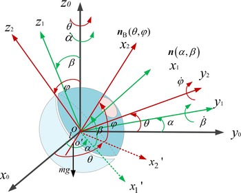
In passive mode, the active hemisphere at the top is driven to rotate idling, while the passive hemisphere at the bottom dents into the GI tract surface adhered with a layer of oil film by the gravity of the DHCR. Thus, the passive hemisphere slides inside the dent of the GI tract surface, and the DHCR could be regarded as a fix center deflection during the posture adjustment. As shown in Fig. 4, the O-x 2 y 2 z 2 rotating magnetic vector coordinate system and the O-x 1 y 1 z 1 Résal coordinate system are established.
The establishment of the coordinate systems.

The O-x
2
y
2
z
2 rotating magnetic vector coordinate system is transformed from the O-x
0
y
0
z
0 coordinate system by two rotations, respectively, one is around the z
0-axis by θ (yaw angle) and the other is around the y
2-axis
 $\varphi$
(pitch angle). In this coordinate system, the normal vector (objective orientation)
n
B is set as the x
2-axis, and the rotating magnetic vector
B
just rotates in the y
2
Oz
2 plane. The transformation matrix from the O-x
0
y
0
z
0 coordinate system to the O-x
2
y
2
z
2 coordinate system is
 \begin{equation} \boldsymbol{{A}}_{2}=\left(\begin{array}{c@{\quad}c@{\quad}c} \cos \theta \cos \varphi & \sin \theta \cos \varphi & \sin \varphi \\[5pt] -\sin \theta & \cos \theta & 0\\[5pt] -\cos \theta \sin \varphi & -\sin \theta \sin \varphi & \cos \varphi \end{array}\right) \end{equation}
In a similar way, the O-x
1
y
1
z
1 Résal coordinate system attached to the DHCR is transformed from the O-x
0
y
0
z
0 coordinate system through rotating
 $\alpha$
(pitch angle) around z
0-axis and
 $\beta$
(yaw angle) around y
1-axis, and the robotic axis
n
is the Ox
1 axis. The transformation matrix from the O-x
0
y
0
z
0 coordinate system to the Résal coordinate system is
 \begin{equation} \boldsymbol{{A}}=\left(\begin{array}{c@{\quad}c@{\quad}c} \cos \alpha \cos \beta & \sin \alpha \cos \beta & \sin \beta \\[5pt] -\sin \alpha & \cos \alpha & 0\\[5pt] -\cos \alpha \sin \beta & -\sin \alpha \sin \beta & \cos \beta \end{array}\right) \end{equation}
where the angles
 $\alpha$
and
 $\beta$
can describe the posture of the robotic axis
n
in the O-x
0
y
0
z
0 rotating magnetic vector coordinate system.
The transformation relation from n ox1 to n ox0 can be obtained as
 \begin{equation} \boldsymbol{{n}}_{ox0}=\boldsymbol{{A}}^{-1}\boldsymbol{{n}}_{ox1} \end{equation}
where the robotic axis
n
in the O-x
0
y
0
z
0 coordinate system can be expressed as
n
ox0 (cos
 $\alpha$
cos
 $\beta$
, sin
 $\alpha$
cos
 $\beta$
, sin
 $\beta$
) and in the O-x
1
y
1
z
1 coordinate system is expressed as
n
ox1 (1,0,0).
During posture adjustment, the changing law of the angles
 $\alpha$
and
 $\beta$
can reflect the motion of the robotic axis, so as to determine the stability of tracking effect.
3.2. Torque analysis
The external torques acting on the DHCR in posture adjustment include the coupling magnetic torque and the viscoelastic resistance torque between the DHCR and the GI tract.
3.2.1 The coupling magnetic torque
The establishment of the rotating magnetic vector coordinate system and the Résal coordinate system also significantly simplifies the coupling magnetic torque model. The rotating magnetic vector B in the O-x 2 y 2 z 2 coordinate system is expressed as
 \begin{equation} \boldsymbol{{B}}_{2}=\left(\begin{array}{c@{\quad}c@{\quad}c} 0 & B_{0}\cos \omega t & B_{0}\sin \omega t \end{array}\right)^{\mathrm{T}} \end{equation}
where B 0 is the magnetic flux density of the magnetic field.
The magnetic dipole moment m of the permanent magnet can be expressed in the Résal coordinate system as
 \begin{equation} \boldsymbol{{m}}=\left(\begin{array}{c@{\quad}c@{\quad}c} 0 & m_{0}\cos \left(\omega t-\delta \right) & m_{0}\sin \left(\omega t-\delta \right) \end{array}\right)^{\mathrm{T}} \end{equation}
where δ is the slip angle between the magnetic dipole moment and the rotating magnetic vector; m 0 is the modulus of the magnetic dipole moment.
The magnetic torque T can be expressed in the Résal coordinate system as
 \begin{equation} \begin{array}{c} \boldsymbol{{T}}=\left(\begin{array}{c@{\quad}c@{\quad}c} T_{x1} & T_{y1} & T_{z1} \end{array}\right)^{\mathrm{T}}=\boldsymbol{{m}}\times \left(\boldsymbol{{A}}^{-1}\boldsymbol{{A}}_{2}\boldsymbol{{B}}_{2}\right)\\[5pt] =m_{0}B_{0}\times \left(\begin{array}{c} \cos \left(\omega t-\delta \right)\left(D_{5}\cos \omega t+D_{6}\sin \omega t\right)-\sin \left(\omega t-\delta \right)\left(D_{3}\cos \omega t+D_{4}\sin \omega t\right)\\[5pt] \sin \left(\omega t-\delta \right)\left(D_{1}\cos \omega t+D_{2}\sin \omega t\right)\\[5pt] -\cos \left(\omega t-\delta \right)\left(D_{1}\cos \omega t+D_{2}\sin \omega t\right) \end{array}\right) \end{array} \end{equation}
where the specific forms of D 1, D 2, D 3, D 4, D 5, and D 6 are following as
 \begin{equation*} \begin{array}{l} D_{1}=-\mathit{\cos }\mathit{\alpha }\cos \beta \sin \theta +\mathit{\sin }\mathit{\alpha }\cos \beta \cos \theta, \\[5pt] D_{2}=\mathit{\cos }\mathit{\alpha }\mathit{\cos }\mathit{\beta }\cos \theta \sin \varphi +\mathit{\sin }\mathit{\alpha }\mathit{\cos }\mathit{\beta }\sin \theta \sin \varphi -\sin \beta \cos \varphi,\\[5pt] D_{3}=\sin \alpha \sin \theta +\cos \alpha \cos \theta, D_{4}=-\mathit{\sin }\mathit{\alpha }\cos \theta \sin \varphi +\mathit{\cos }\mathit{\alpha }\sin \theta \sin \varphi,\\[5pt] D_{5}=-\mathit{\cos }\mathit{\alpha }\sin \beta \sin \theta -\mathit{\sin }\mathit{\alpha }\sin \beta \cos \theta, \\[5pt] D_{6}=-\mathit{\cos }\mathit{\alpha }\mathit{\sin }\mathit{\beta }\cos \theta \sin \varphi -\mathit{\sin }\mathit{\alpha }\mathit{\sin }\mathit{\beta }\sin \theta \sin \varphi +\cos \beta \cos \varphi. \end{array} \end{equation*}
3.2.2 Dynamic resistance torque
During the rotating process of the DHCR for posture adjustment, the deformed GI tract surface and the digestive fluid exert a viscoelastic damping effect on the DHCR [Reference Flom and Bueche28, Reference Johnson29]. According to the transformation process in Fig. 4, the passive hemisphere of the DHCR rotates around the z 0-axis and the y 1-axis. The viscoelastic damping effect on the DHCR can be expressed as
 \begin{equation} \left\{\begin{array}{l} M_{fy1}=-k\dot{\beta }\\[5pt] M_{fz2}=-k\dot{\alpha } \end{array}\right. \end{equation}
where
 $\dot{\alpha }$
and
 $\dot{\beta }$
are the angular velocity around the z
0-axis and the y
1-axis, respectively, and k is the damping coefficient between the DHCR and the contact surface. And the dynamic resistance torque
M
f
in the Résal coordinate system can be obtained as
 \begin{equation} \boldsymbol{{M}}_{f}=\left(\begin{array}{l} M_{fx1}\\[5pt] M_{fy1}\\[5pt] M_{fz1} \end{array}\right)=\left(\begin{array}{l} -k\dot{\alpha }\sin \beta \\[5pt] -k\dot{\beta }\\[5pt] -k\dot{\alpha }\cos \beta \end{array}\right) \end{equation}
3.2.3 Total External Torque
According to Eqs. (11) and (12), the total external torque of DHCR can be written as
 \begin{equation} \left\{\begin{array}{l} M_{x1}=T_{x1}-k\dot{\alpha }\sin \beta \\[5pt] M_{y1}=T_{y1}-k\dot{\beta }\\[5pt] M_{z1}=T_{z1}-k\dot{\alpha }\cos \beta \end{array}\right. \end{equation}
When the DHCR reaches the equilibrium state toward the target orientation, without any pitch and yaw motion, the active hemisphere only rotates synchronously with the magnetic vector with the angular velocity
 $\omega$
, thus, M
x1 = 0.
3.3. Dynamic equations
The DHCR has a multirigid structure with complex internal forces, which need not be considered in the Lagrange equation. Thus, the dynamic movement of the DHCR can be described by the Lagrange equation as
 \begin{equation} \frac{d}{dt}\left(\frac{\partial L}{\partial \dot{q}_{i}}\right)-\frac{\partial L}{\partial q_{i}}=Q_{i} \end{equation}
where q
i
(
 $\alpha$
and
 $\beta$
) are the generalized coordinate, Q
i
is the generalized torque in the generalized coordinate system, and L = T
L
-V
L
is the Lagrangian, where T
L
and V
L
are the kinetic and potential energies, respectively.
The angular velocity
 $\boldsymbol{\omega}$
a of the active hemisphere and the angular velocity
 $\boldsymbol\omega$
p of the passive hemisphere in the Résal coordinate system can be expressed as
 \begin{equation} \boldsymbol{\omega }_{a}=\left(\begin{array}{l} \omega _{ax1}\\[5pt] \omega _{ay1}\\[5pt] \omega _{az1} \end{array}\right)=\left(\begin{array}{c@{\quad}c@{\quad}c} \cos \beta & 0 & -\sin \beta \\[5pt] 0 & 1 & 0\\[5pt] \sin \beta & 0 & \cos \beta \end{array}\right)\cdot \left(\begin{array}{l} 0\\[5pt] 0\\[5pt] \dot{\alpha } \end{array}\right)+\left(\begin{array}{l} \omega \\[5pt] \dot{\beta }\\[5pt] 0 \end{array}\right)=\left(\begin{array}{c} \omega -\dot{\alpha }\sin \beta \\[5pt] \dot{\beta }\\[5pt] \dot{\alpha }\cos \beta \end{array}\right) \end{equation}
 \begin{equation} \boldsymbol{\omega }_{p}=\left(\begin{array}{l} \omega _{px1}\\[5pt] \omega _{py1}\\[5pt] \omega _{pz1} \end{array}\right)=\left(\begin{array}{c@{\quad}c@{\quad}c} \cos \beta & 0 & -\sin \beta \\[5pt] 0 & 1 & 0\\[5pt] \sin \beta & 0 & \cos \beta \end{array}\right)\cdot \left(\begin{array}{l} 0\\[5pt] 0\\[5pt] \dot{\alpha } \end{array}\right)+\left(\begin{array}{l} 0\\[5pt] \dot{\beta }\\[5pt] 0 \end{array}\right)=\left(\begin{array}{c} -\dot{\alpha }\sin \beta \\[5pt] \dot{\beta }\\[5pt] \dot{\alpha }\cos \beta \end{array}\right) \end{equation}
The kinetic energy T L of DHCR in the passive mode is
 \begin{align} T_{L}&=\frac{1}{2}J_{1}\omega _{ax1}^{2}+\frac{1}{2}J_{2}\omega _{px1}^{2}+\frac{1}{2}J_{e}\left(\omega _{py1}^{2}+\omega _{pz1}^{2}\right) \nonumber \\[5pt] & =\frac{1}{2}J_{1}\left(\omega -\dot{\alpha }\sin \beta \right)^{2}+\frac{1}{2}J_{2}\left(-\dot{\alpha }\sin \beta \right)^{2}+\frac{1}{2}J_{e}\left(\dot{\alpha }\cos \beta \right)^{2}+\frac{1}{2}J_{e}\dot{\beta }^{2} \end{align}
where J 1 and J 2 are the polar moments of inertia of the active and passive hemisphere, respectively, J e is the equatorial moment of inertia of the whole DHCR.
Assuming that the center of the DHCR locates in the zero potential plane, thus, the potential energy V L of DHCR is
 \begin{equation} V_{L}=-{mgl} \, \text{sin} \beta \end{equation}
where l is the distance from the center of gravity to the center of DHCR.
Substituting (17) and (18) into (14), the posture dynamic modeling of the DHCR in passive mode can be obtained:
 \begin{equation} \left\{\begin{array}{l} \ddot{\alpha }\left[\left(J_{1}+J_{2}\right)\sin ^{2}\beta +J_{e}\cos ^{2}\beta \right]+2\left(J_{1}+J_{2}-J_{e}\right)\dot{\alpha }\dot{\beta }\sin \beta \cos \beta -J_{1}\omega \dot{\beta }\cos \beta =Q_{1}\\[5pt] J_{e}\ddot{\beta }-\left(J_{1}+J_{2}-J_{e}\right)\dot{\alpha }^{2}\sin \beta \cos \beta +J_{1}\omega \dot{\alpha }\cos \beta +{mgl} \, \text{cos} \beta =Q_{2} \end{array}\right. \end{equation}
where the generalized torque Q
1 = M
z1cos
 $\beta$
and Q
2 = M
y1.
For the dynamic model (19) also can be formulated in a similar manner as the form:
 \begin{equation} \boldsymbol{{M}}\!\left(\boldsymbol{{q}}\right)\ddot{\boldsymbol{{q}}}+\boldsymbol{{C}}\!\left(\boldsymbol{{q}},\dot{\boldsymbol{{q}}}\right)\dot{\boldsymbol{{q}}}+\boldsymbol{{G}}\!\left(\boldsymbol{{q}}\right)+\boldsymbol{{M}}_{f}\!\left(\dot{\boldsymbol{{q}}}\right)=\boldsymbol{{T}} \end{equation}
where
T
is the torque input,
 $\boldsymbol{{M}}_{f}\!\left(\dot{\boldsymbol{{q}}}\right)$
is the resistance torque,
 $\boldsymbol{{M}}\!\left(\boldsymbol{{q}}\right)$
and
 $\boldsymbol{{C}}\!\left(\boldsymbol{{q}},\dot{\boldsymbol{{q}}}\right)$
are the inertia matrix and centrifugal force and Coriolis force matrix, and
 $\boldsymbol{{G}}\!\left(\boldsymbol{{q}}\right)$
is the gravity item, respectively.
4. Dynamic characteristics analysis
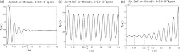
The dynamic Eq. (19) has complex nonlinear characteristics, in terms of the high-order coupling nonlinear time-varying oscillators. The external torque has an obvious effect on the posture response of the DHCR. Three response forms can be obtained under different parameters (the magnetic flux density B
0 and the angular velocity
 $\omega$
of the rotating magnetic vector and the damping coefficient k of the GI tract surface), as shown in Fig. 5, and the other simulation parameters are shown in Table II.
Three response under different typical control conditions: (a) asymptotic stable, (b) periodic oscillation, and (c) divergent.

The simulation parameters of the DHCR.

In order to achieve stable posture alignment by dynamic tracking effect, the stability domain and the influence of each factor (B
0 and
 $\omega$
and k ) are discussed.
4.1. Critical stability control line and stable domain
In complex GI tract environment, the control parameters (B
0 and
 $\omega$
) need to be adjusted in the stability domain to achieve precise control. Then, the critical values B
c and
 $\omega$
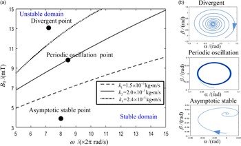
c are selected when the system is periodic oscillation, and the critical stability control lines with different k are shown in Fig. 6(a).
In Fig. 6(a), the domain is divided into two parts by the critical line. In the upper region, the system phase diagram in Fig 6(b) with angles
 $\alpha$
and
 $\beta$
as state variables is divergent, which indicates that the system is unstable. On the contrary, the DHCR can keep the posture stable in the lower region, and the system phase diagram is asymptotic stable at objective orientation. When the selected parameters are near the critical line, the system phase diagram is periodic oscillation. The lower area can be called the stable domain.
4.2. The influence of parameters on stability
4.2.1 Magnetic flux density
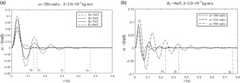
From Fig. 6(a), taking B 0 as the single variable, when B 0 is less than B c, the system can finally stabilize at a predetermined orientation; when B 0 is greater than B c, the system is unstable. It shows that with the increase of B 0, the system changes from a stable state to an unstable state. The simulation results with different magnetic flux density B 0 in stable domain are shown in Fig. 7(a). The smaller B 0 can decrease the vibration amplitude, and the time to achieve a stable state. Thus, proper reduction of B 0 is beneficial for the system to reach a stable state. It is noteworthy that when B 0 is too smaller, the effect of the resistance torque is enhanced, not conducive to subsequent posture adjustment, thus, this situation should be avoided.
(a) The critical stability control lines with different k; (b) the system phase diagram with the angle
 $\alpha$
and
 $\beta$
.

(a) Response curves of the posture angle
 $\alpha$
with different values of B
0 and (b) the response curves of the posture angle
 $\alpha$
with different values of
 $\omega$
.

4.2.2 Angular velocity
From Fig. 6(a), taking
 $\omega$
as the single variable, when
 $\omega$
is less than
 $\omega$
c, the system is unstable; when
 $\omega$
is greater than
 $\omega$
c, the system can finally stabilize at a predetermined orientation. With the decrease of
 $\omega$
, the system changes from an unstable state to a stable state. The simulation results with different angular velocity
 $\omega$
in stable domain are shown in Fig. 7(b). The larger
 $\omega$
can decrease the vibration amplitude and the time to achieve stable state. Thus, it can be inferred that in the control progress, the
 $\omega$
can be appropriately increased to quickly reach a stable state. But it is noteworthy that when
 $\omega$
is too large, damage to the GI tract will be caused.
4.2.3 Damping coefficient
The damping coefficient k is an environmental factor, which would affect the selection of B
0 and
 $\omega$
, and then affect the stability of the system. In the actual control progress, the appropriate medium is selected to attenuate the change of k and keep it as constant as possible. Compared to the critical stability control lines with different k in Fig. 6(a), it is found that when k increases, the critical stability control line moves up, and the stable domains of B
0 and
 $\omega$
are expanded. In other words, the larger k is conducive to stability. The parameters in the stable domain can ensure stable operation.
In general, the determination of the stable domain clarifies the adjustable range of the magnetic flux density B
0 and the angular velocity
 $\omega$
and provides the theoretical basis for subsequent precise control.
5. Sliding mode controller
Due to its uncertainty in complex GI tract environment such as different liquid viscosity and GI surface smoothness, the modeling perturbation cannot be avoided. In order to improve tracking performance of the DHCR, sliding mode control method based on the nominal model [Reference Fateh and Khorashadizadeh30, Reference Hajiani and Khorashadizadeh31] is employed to accurately control the posture of the DHCR, which has complete robustness. Therefore, we take e = q d- q as tracking error, choose S as the sliding control surface. The sliding surface and control law are designed as
 \begin{equation} \boldsymbol{{S}}\boldsymbol{=}\dot{\boldsymbol{{e}}}\boldsymbol{+}\boldsymbol{\lambda }\boldsymbol{{e}} \end{equation}
 \begin{equation} \boldsymbol{{T}}=\boldsymbol{{M}}_{\mathrm{0}}\!\left(\ddot{\boldsymbol{{q}}}_{\mathrm{d}}+\boldsymbol{\lambda }\dot{\boldsymbol{{e}}}\right)+\boldsymbol{{C}}_{\mathrm{0}}\!\left(\dot{\boldsymbol{{q}}}_{\mathrm{d}}+\boldsymbol{\lambda }\boldsymbol{{e}}\right)+\boldsymbol{{G}}_{\mathrm{0}}+\boldsymbol{{M}}_{f0}+\boldsymbol{{K}}_{r}\mathrm{sgn}\left(\boldsymbol{{S}}\right) \end{equation}
where
M
0,
C
0,
G
0, and
M
f0 are the nominal values of
M
,
C
,
G,
and
M
f
. Δ
M
=
M
-
M
0, Δ
C
=
C
-
C
0, Δ
G
=
G
-
G
0, Δ
M
f
=
M
f
-
M
f0 are the deviations between nominal model and actual model.
 $\boldsymbol\lambda$
= diag(
 $\lambda$
1,
 $\lambda$
2),
K
r = diag(r
1, r
2) are positive diagonal matrix.
We choose Lyapunov function as
 \begin{equation} V\boldsymbol{=}\frac{1}{2}\boldsymbol{{S}}^{\mathrm{T}}\boldsymbol{{MS}} \end{equation}
According to
 $\dot{\boldsymbol{{M}}}-2\boldsymbol{{C}}$
is a skew symmetric matrix, and the Eqs. (20) and (21), the derivation of
V
can be obtained as
 \begin{align} \dot{V}&=\frac{1}{2}\boldsymbol{{S}}^{\mathrm{T}}\dot{\boldsymbol{{M}}}\boldsymbol{{S}}+\boldsymbol{{S}}^{\mathrm{T}}\boldsymbol{{M}}\dot{\boldsymbol{{S}}} \nonumber\\[5pt] &=\frac{1}{2}\boldsymbol{{S}}^{\mathrm{T}}\left(\dot{\boldsymbol{{M}}}-2\boldsymbol{{C}}\right)\boldsymbol{{S}}+\boldsymbol{{S}}^{\mathrm{T}}\boldsymbol{{CS}}+\boldsymbol{{S}}^{\mathrm{T}}\boldsymbol{{M}}\dot{\boldsymbol{{S}}} \nonumber \\[5pt] &=\boldsymbol{{S}}^{\mathrm{T}}\left(\boldsymbol{{M}}\left(\ddot{\boldsymbol{{q}}}_{\mathrm{d}}+\boldsymbol{\lambda }\dot{\boldsymbol{{e}}}\right)+\boldsymbol{{C}}\left(\dot{\boldsymbol{{q}}}_{\mathrm{d}}+\boldsymbol{\lambda }\boldsymbol{{e}}\right)+\boldsymbol{{G}}+\boldsymbol{{M}}_{f}-\boldsymbol{{T}}\right) \end{align}
therefore, by using control low in Eq. (22), we have
 \begin{equation} \dot{V}=\boldsymbol{{S}}^{\mathrm{T}}\left(\Delta \boldsymbol{{M}}\left(\ddot{\boldsymbol{{q}}}_{\mathrm{d}}+\boldsymbol{\lambda }\dot{\boldsymbol{{e}}}\right)+\Delta \boldsymbol{{C}}\left(\dot{\boldsymbol{{q}}}_{\mathrm{d}}+\boldsymbol{\lambda }\boldsymbol{{e}}\right)+\Delta \boldsymbol{{G}}+\Delta \boldsymbol{{M}}_{f}-\boldsymbol{{K}}_{r}\mathrm{sgn}\left(\boldsymbol{{S}}\right)\right) \end{equation}
Thus, we select the coefficients
 \begin{equation} r_{i}\gt ||\Delta \boldsymbol{{M}}||_{\max }||\ddot{\boldsymbol{{q}}}_{\mathrm{d}}+\boldsymbol{\lambda }\dot{\boldsymbol{{e}}}||+||\Delta \boldsymbol{{C}}||_{\max }||\dot{\boldsymbol{{q}}}_{\mathrm{d}}+\boldsymbol{\lambda }\boldsymbol{{e}}||+||\Delta \boldsymbol{{G}}||_{\max }+||\Delta \boldsymbol{{M}}_{f}||_{\max } \end{equation}
then,
 $\dot{V}\leq 0$
is obtained, therefore the control system is proved to be stable. Figure 8 presents a schematic diagram for the posture control of the DHCR.
Block diagram of the sliding mode controller for the DHCR.

According to the control law (22) and the Eq. (10), the control parameters such as magnetic flux density and angular velocity can be adjusted to apply the magnetic torque, so as to realize the posture alignment of the DHCR.
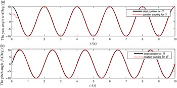
The simulation is carried out to verify the effectiveness of the controller to achieve an ideal control performance by overcoming the influence of the uncertainties. Assuming that the initial condition is (5o, 5o), the ideal trajectory of the DHCR’s axis is
 $\alpha =10\cos\!\left(\pi t\right),\beta =10\sin\!\left(\pi t\right)$
. To consider the parametric uncertainty, thus, the parameter of the nominal model used in the control law can be given as 0.8 of the real ones [Reference Li, Bai and Madsen32]. And the control parameters
 $\boldsymbol\lambda$
= diag(20, 20), and the
K
r can be obtained by (26).The simulation results are shown in Fig. 9. We can observe that the movement is relatively stable during the process of tracking the pitch and yaw angle. The simulation results show that the controller has a good trajectory tracking ability.
Simulation results of posture tracking performance. (a) Tracking curve of pitch angle
 $\alpha$
. (b) Tracking curve of yaw angle
 $\beta$
.

6. Experimental verification
6.1. Experimental set-up
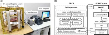
In order to verify the theoretical analysis results, the experimental set-up is built, as shown in Fig. 10. The platform consists of the tri-axis orthogonal square Helmholtz coils, the control system of the rotating magnetic vector, the host computer, and the prototype of the DHCR. During posture alignment control, first, when the control parameters (B
0,
 $\omega$
, q
d
) are input to the host computer, the control system can input three-phase alternating current to the tri-axis orthogonal square Helmholtz coils to generate the SURMV. Then, the corresponding tracking torque can be generated to rotate the DHCR; thus, the axis of DHCR can keep tracking the normal orientation of the SURMV. The GI tract image can be acquired and displayed on the computer, and observation can be performed based on the image. Finally, we repeat the above steps for the next scan point observation until the GI screening is completed.
The (a) experimental set-up and (b) system architecture of the DHCR system.

6.2. Motion and dynamic characteristics test
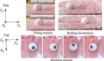
In motion and stability test, as shown in Fig. 11, the DHCR is placed in a simulated GI tract environment, in which the tilting motion is tested in z 0 oy 0 plane, the rotation motion is tested around the z 0-axes, and the rolling locomotion is tested along the y 0-axes. We find that three motions of the DHCR can be realized by the normal vector n B navigation based on tracking effect.
Motion test of the DHCR.

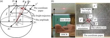
To verify the posture stability domains by tracking effect, the orientation measuring device of the DHCR axis is developed. The schematic diagram of the device is shown in Fig. 12. The camera module is replaced with a laser diode. The coordinates of the bright trajectory are converted into the amplitude of the oscillation to estimate the stability. The coordinate paper is placed at l = 80 mm above the sphere center of the DHCR. The bright spot of the laser diode on the coordinate paper can reflect the bright trajectory of the axis in real time, and the trajectory can be recorded by the video measuring device. Setting the initial orientation of the DHCR is (0o,80o), and the objective orientation of the rotating magnetic vector is (0o,90o), which is convenient to measure accurately with the smaller magnetic field error and to read the posture of the DHCR.
The (a) schematic diagram and (b) orientation measuring device.

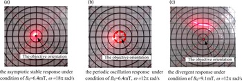
By observing the trajectory of the DHCR axis, it can be found that there are three kinds of responses under different parameters: asymptotic stable response, periodic oscillation response, and divergent response, as shown in Fig. 13, consistent with the Fig. 6(b).
The snapshot of the trajectory of the DHCR axis.

The prerequisite for obtaining accurate posture alignment is to ensure the stability of dynamic tracking effect. Thus, to obtain the stability domains of control parameters, the critical stability values are measured with different magnetic flux densities B
0, angular velocities
 $\omega$
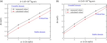
, and the damping coefficients k of the DHCR. Figure 14 is a comparison diagram of the measured values and calculated values of the critical stability control lines. Because the effect of GI tract environment on the DHCR is simplified in the theoretical model, the calculated values are smaller than the measured values, while the differences between two values are smaller, indicating that the numerical results of the critical control line are close to the experimental results. We also notice that when k increases, the stability domain of magnetic flux density and angular velocity is significantly expanded, and the difference between the calculated values and the measured values decreases, indicating that the larger k is conducive to stability.
Critical stability control lines with different k.

Then, the experiments are carried out to verify the influence of control parameters (magnetic flux density B
0 and angular velocity
 $\omega$
) in stability domain on stability. The amplitude of the oscillation of the DHCR can be used to evaluate the stability of tracking effect. Figure 15 shows the amplitude of the oscillation of the DHCR when B
0 is from 6 to 10mT (when
 $\omega$
= 20π rad/s), and
 $\omega$
is from 12 to 20 rad/s (when B
0 = 6.4mT). From the Fig. 15, it can be found that the amplitude of the oscillation is directly proportional to magnetic flux density and inversely proportional to the angular velocity. The experiment results are consistent with the theoretical calculation in Fig. 6. In general, in the case of the asymptotic stable response, we can obtain:
-
The magnetic flux density B 0 is smaller, and its stability is better.
-
The larger the angular velocity
 $\omega$
(larger than the critical value
$\omega$
c ) is beneficial to its stability.
-
The larger damping coefficient k is beneficial to its stability.


The amplitude of the oscillation of the DHCR versus the magnetic flux density B
0 and angular velocity
 $\omega$
.

6.3. Posture alignment performance test
To verify validity and efficiency of the dynamic tracking effect, the posture alignment performance tests are carried out. The sliding mode control algorithm is embedded into the control system, and the corresponding tracking torque can be generated to rotate the DHCR after the control parameters are input. Then the yaw angle and pitch angle errors of the DHCR are measured. The results are compared with open loop control, as shown in Table III. The results show that both control methods can achieve posture alignment with small errors, less than the ALICE system [Reference Lee, Choi, Go, Jeong, Young Ko, Park and Park16], and the sliding mode control method further improves the posture alignment performance.
Posture tracking error verification results.

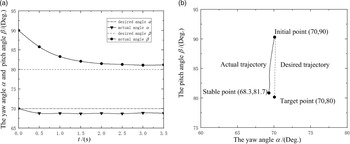
The curves of the (a) the yaw angle and pitch angle and (b) trajectory of the DHCR’s axis.

Figure 16 shows the curves of the yaw angle and pitch angle and trajectory of the DHCR’s axis when the target point is (70o, 80o). Once the target orientation parameters are determined, the DHCR can respond quickly under the uniform SURMV and eventually stabilized near the objective orientation. Thus, it can be seen that the axis of the robot will track the normal vector of the rotating magnetic vector efficiently and precisely.
7. Conclusion
One contribution of this paper lies in the DHCR structure, which can realize the fix-point posture adjustment based on tracking effect in terms of dynamic balance control, as a result, the posture alignment can separate from the locomotion without any mutual influence. The other contribution lies in the dynamic modeling of the posture adjustment using decoupled control variables, aiding the stability analysis and determination of posture stability domain. Furthermore, the sliding mode control based on the nominal model is employed to achieve dynamic tracking more accurately. The theoretical analyses and the experiments show that the DHCR’s axis can be navigated accurately, and the efficiency is based on dynamic tracking effect. The work has provided an innovative method for the precise control of capsule robots in future clinical applications.
Acknowledgment
This work was supported in part by the National Natural Science Foundation of China under Grant 62173059 and Grant 61773084.
Conflicts of interest
We declare that we do not have any commercial or associative interest that represents a conflict of interest in connection with the work submitted.
Authorship contribution statement
Yongshun Zhang: conceived and designed the study, wrote original draft.
Xu Liu: wrote original draft and performed statistical analyses.
Zhenhu Liu and Zihao Zhao: conducted data gathering and performed statistical analyses.
Hai Dong and Dianlong Wang: supervised experiments, conducted review & editing.