


I. INTRODUCTION
Dielectric lens antennas are gaining ground in diverse application areas in microwave and millimeter-wave systems because of their acceptable size and attractive performance regarding beam shaping, sidelobe suppression, and beam steering, among others [Reference Thornton and Huang1]. The availability of low-loss dielectric materials and efficient manufacturing processes give way to the realization of lens structures for integrated systems featuring one-dimensional (1D) or two-dimensional (2D) electronically controlled beam steering [Reference Thornton and Huang1–Reference Yurduseven, Cavallo and Neto7]. Lens-based systems, however, experience a limitation of coverage to rather narrow sectors because of aberration effects reducing the focusing at larger off-axis angles [Reference Artemenko, Mozharovskiy, Maltsev, Maslennikov, Sevastyanov and Ssorin8, Reference Filipovic, Gauthier, Raman and Rebeiz9].
The quest for solutions allowing electronic beam steering over particularly wide solid angle leads to renewed interest in gradient-index lenses. The historic Luneburg lens [Reference Luneburg10] with spherical symmetry and radially varying permittivity operates theoretically over a 4π sr solid angle. The challenges of the realization of Luneburg lens are twofold. First, the practical realization of a dielectric material with the prescribed spatial variation of permittivity, to be realized in combination with requirements regarding low loss, homogeneity to a scale of a fraction of a wavelength, low weight, low cost of production. Second, the radiation elements are placed at the foci of lens and thus must be mounted on a spherical surface which is a requirement incompatible with cost-efficient assembly technology. The problem of a dielectric material with spatially varying, well-defined permittivity can be somewhat alleviated by a stepwise approximation of the required profile of the permittivity [Reference Peeler and Coleman11, Reference Yang, Tang and Hao12]. However, materials of some specific required permittivity may not be available; then the design of the step approximation is constrained and likely severely compromised by the choice of materials. Alternatively, an effective permittivity of arbitrary value can be realized by a mixture of a dielectric and air. This is often accomplished by either drilling holes of specific diameter and density into dielectric solids [Reference Imbert, Romeu and Jofre13, Reference Rondineau, Himdi and Sorieux14], or by 3D printing a “honeycomb” structure of the dielectric [Reference Liang, Ng, Chang, Gbele, Gehm and Xin15]. In both cases, the maximum frequency of operation of the lenses obtained by the machining process is limited as the inhomogeneity of the material must be much smaller than the wavelength. An attractive method to control a local variation of the effective permittivity of a material is based on pressing plastic foam to a desired density corresponding to a specific value of permittivity [Reference Merlet, Le Bars, Lafond and Himdi16, Reference Bor, Lafond, Merlet, Le Bars and Himdi17]. Thermal treatment of the foam after pressing causes plastic deformation instead of elastic deformation. At millimeter waves, however, loss tangent of the material can be significant. Applying this technique, different planar lens structures operating at millimeter waves have been demonstrated [Reference Bor, Fuchs, Lafond and Himdi18, Reference Bor, Fuchs, Lafond and Himdi19].
In this paper, a dielectric lens with stepwise varying permittivity is realized using dielectric materials made as mixtures of fine-grained high-permittivity alumina ceramic powder and fine-grained low-permittivity hollow glass bubble powder. In a range defined by the two mixed components, an arbitrary permittivity can be obtained by simply changing the ratio of the two mixed powder parts. In addition, the grain size of < 0.1 mm guarantees homogeneity of the mixture up to very high frequency.
The basic topology of the lens antennas is described in Section 2. The design, construction, and measurements of a planar antenna, which is utilized as feed radiator for the lenses is presented in Section 3. Then, two examples of lens antennas are described in Section 4, and simulations as well as measurements results are shown in Section 5. Conclusions are given in Section 6.
II. ANTENNA TOPOLOGY
Figure 1 shows the basic topology of the proposed antenna. The structure is composed by a brick-shaped stepped-index focusing lens and a low-gain feed radiator positioned at the focal point. The lens brick is sandwiched between two metal plates forming a parallel-plate waveguide. Depending on the orientation of the feed radiator placed between the two metal plates, the antenna operates in the TEM (transverse electromagnetic) mode or in the first higher-order TE (transverse electric) mode of the parallel-plate waveguide. Diffraction at the end of the metal plates is reduced by a short linear taper. The taper dimensions (length 9 and height 3 mm) are optimized by field simulations with the goal to reduce reflection of a transmitted TEM mode. As a result, the taper reduces some of the larger side lobes of the TEM-mode antenna and slightly increases the directivity of both TEM- and TE-mode antennas. Simulations of the complete antennas with and without taper indicate an increase of directivity of about 0.5 dB due to the presence of the taper.
Basic topology of flat lens antenna.

The two antenna prototypes are designed for a frequency of 12 GHz. The transverse dimension of the lens brick is 125 mm, corresponding to five free-space wavelengths. The distance between the two metal plates, equaling the height of the lens brick, is h TEM = 26 mm for the TEM-mode antenna, and it is h TE = 20 mm for the TE1-mode antenna. The TE1 mode is dispersive and for the chosen distance h TE, cutoff is at 7.5 GHz.
The overall lens antenna and the low-gain feed radiator are analyzed using a finite-element electromagnetic field simulation tool (CST Microwave Studio, CST GmbH, Darmstadt, Germany).
III. FEED RADIATOR
A compact planar slot antenna acts as a feed radiator to excite the lens in its focal point. The slot antenna excites the parallel-plate waveguide in either TEM or TE1 mode and shows a wide end-fire radiation beam with small sidelobes. Starting with the design proposed in [Reference Hua, Yang, Wu and Wu20], the slot antenna radiation pattern has been improved for reduced main beam tilt and better pattern symmetry. This is primarily achieved by replacing the microstrip feed of [Reference Hua, Yang, Wu and Wu20] by an in-line coax-to-CPW (co-planar waveguide)-to-slotline transition.
The antenna shown in Fig. 2 is realized on dielectric substrate Rogers RO4003C (thickness 1.52 mm, datasheet permittivity ε r = 3.38, and tan δ = 0.0027). The dimensions L = 13.3, W = 7.5, L d = 6.3, and w d = 0.6 mm are optimized for the low sidelobe level.
Planar slot antenna as feed radiator. Left: Overall layout. Right: Detailed view of the CPW-to-slotline transition with schematic drawings of E-field distribution in different cross-sectional planes of the transition.

A coaxial connector feeds the slot antenna. The coaxial-to-slotline transition is implemented in four steps: (1) a coaxial-to-50-Ω-grounded CPW (1–1′) transition is optimized by using vias holes along the CPW line; (2) a quarterwave impedance transformer transforms the grounded 50-Ω CPW to an ungrounded 100-Ω CPW (2–2′); (3) based on [Reference Ma and Itoh21], the odd mode ungrounded CPW (3–3′) is achieved by extending only one slot of the previous CPW structure by a 180° length; and (4) the center conductor ends thus forming the slotline (4–4′). A slotline shunt capacitance (L C = 1.95 mm) improves the antenna impedance match.
Figure 3 shows a photograph of the planar slot radiator with mounting holes as used for the TE1-mode lens antenna prototype. The slot radiator for the TEM-mode lens antenna prototype is identical but the mounting holes are clipped off to fit the radiator between the metal plates of the parallel-plate waveguide. The simulation of the radiation characteristics of the antenna indicates the phase center located at the beginning of the linear slot tapers.
Photograph of the planar slot radiator with mounting holes as used for the TE1-mode lens antenna prototype (W g = 30 mm). The simulated phase center is located at L p = 15 mm from the antenna aperture.

Figure 4 shows measured and simulated impedance match of the planar slot radiator within a free-space environment. The simulated gain is 8.6 dBi at 12 GHz and the simulated efficiency is 95%. Figure 5 shows measured and simulated radiation patterns at 12 GHz. There is good agreement between simulations and measurements.
Measured and simulated impedance match of the planar slot radiator.

Measured and simulated radiation patterns at 12 GHz of the planar slot radiator. Top: E-plane. Bottom: H-plane.

IV. DESIGN OF THE DIELECTRIC STEPPED-INDEX FLAT LENS
Mixing different microscopic dielectric particles of different permittivity leads on a macroscopic scale, to a resulting dielectric with new, specific permittivity. Depending on mixing ratio, particle size and shape and orientation, and respective permittivities of the mixing partners, the resulting dielectric permittivity can be predicted by several electromagnetic models [Reference Sihvola22]. For the special case of high-permittivity particles embedded in a low-permittivity environment, particularly high sensitivity of the resulting dielectric permittivity is observed a high-volume fraction of the high-permittivity particles. This behavior can be explained by the onset of percolative strings of high-permittivity particles and their orientation. As a consequence, modeling will typically not result in reliable results for the resulting dielectric permittivity. Thus, accurate measurements of the resulting dielectric permittivity are necessary.
Mixtures of alumina ceramic, glass, and air are used for the dielectric stepped-index flat lens. The mechanical and dielectric properties of fine-grained alumina ceramic powder from Inframat and tiny hollow glass bubbles from 3 M are shown in Table 1. Mixing these two components in different ratios leads to permittivity values in the range from ε rel = 1.13 (glass bubbles only) and ε rel = 3.24 (alumina powder only). Considering the small particle sizes and the operation frequency, the mixture on a macroscopic scale is assumed as isotropic and homogeneous. The pure glass bubbles tend to behave very dusty, therefore a minimum alumina volume fraction of 10% is mixed with the glass bubbles, leading to a minimum permittivity of ε rel = 1.31 as a constraint for the design of the dielectric stepped-index flat lens. In addition to mixing different ratios, applying large mechanical pressure to the mixture will also lead to an increase of permittivity by irreversibly breaking some of the hollow glass bubbles. Using a suitable form and a press, the resulting dielectric permittivity of a mixture can be fine-tuned rather easily.
Characteristics of the materials used for the dielectric stepped-index flat lens.

The dielectric characteristic of the mixture is measured using a rectangular waveguide setup as shown in Fig. 6. A shorted WR90 waveguide section of 2 cm length is filled with the mixture. The measured complex reflection coefficient is then compared with the electromagnetic field simulation of the setup where complex permittivity (ε rel and tan δ) is a fitting parameter.
Photograph of the WR90 section filled with dielectric mixture, used to determine the complex permittivity.

The calculation of the permittivity profile of the dielectric stepped-index flat lens is based on a geometrical optics approach. As described in [Reference Thornton and Huang1] for the similar case of a one-surface-refracting lens, the rays originating from the focal point and crossing through the flat lens structure are delayed by materials of appropriate permittivity in order to produce an equal-phase wave front on the adjacent lens surface. Referring to Fig. 7, the phase of a signal along trace FOP must equal the phase of a signal along FO′P′. Therefore,
 $$\beta _0F + a\beta _L\left( {y = 0} \right) = \beta _0\sqrt {F^2 + y^{{\prime}2}} + a\beta _L\left( {y = y^{\prime}} \right).$$
Geometry of the dielectric stepped-index flat lens.

The propagation constant β depends on both permittivity and propagation mode. For the TEM mode of the parallel-plate waveguide (resulting in a x-polarized radiation according to the coordinate system in Fig. 7),
 $$\beta _0 = \displaystyle{{2\pi f} \over {c_0}},$$
 $$\beta _L = \displaystyle{{2\pi f} \over {c_0}}\sqrt {\varepsilon _{rel}}, $$
where c 0 denotes the speed of light in free space. For the TE1 mode (y-polarized radiation) follows accordingly:
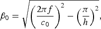 $$\beta _0 = \sqrt {{\left( {\displaystyle{{2\pi f} \over {c_0}}} \right)}^2 - {\left( {\displaystyle{\pi \over h}} \right)}^2}, $$
 $$\beta _L = \sqrt {{\left( {\displaystyle{{2\pi f} \over {c_0}}} \right)}^2\varepsilon _{rel} - {\left( {\displaystyle{\pi \over h}} \right)}^2}, $$
where h is the separation distance of the parallel plates. The permittivity profile of the lens is derived from (1) to (3) for the TEM version as
 $$\varepsilon _{rel}^{TEM} \left( {y^{\prime}} \right) = \left( {\displaystyle{{F - \sqrt {F^2 + y^{{\prime}2}}} \over a} + \sqrt {\varepsilon _{rel}^{TEM} \left( {y = 0} \right)}} \right)^2$$
and from (1), (4), (5) for the TE-mode version of the antenna as
 $$\eqalign{ \varepsilon _{rel}^{TE} \left( {y^{\prime}} \right) &= \Bigg(\displaystyle{{\sqrt {1 - {(\lambda _0/2h)}^2} (F - \sqrt {F^2 + y^{{\prime}2}} )} \over a} + \cr & \quad\left. {\sqrt {\varepsilon _{rel}^{TE} \left( {y = 0} \right) - {\left( {\displaystyle{{\lambda _0} \over {2h}}} \right)}^2}} \right)^2 + \left( {\displaystyle{{\lambda _0} \over {2h}}} \right)^2.} $$
The separation distance of the parallel plates determines one dimension of the antenna aperture and therefore beamwidth and directivity. In order to achieve large directivity, h should be large. On the other hand, the distance h must be small enough to avoid the propagation of unwanted modes. For the TE1 mode (y-polarization in Fig. 7), the plate separation distance must be at least half-wavelength (cutoff of TE1 mode). The first unwanted higher-order mode TE3 has cut off when the separation distance h equals three half wavelengths. Because of the symmetry of the structure, the TE2 mode, though above cutoff in parts of the lens, is not excited. Considering a maximum permittivity of ε rel = 3.24 in the lens, the criterion of “three half wavelengths” plate separation at 12 GHz calls for h < 20.8 mm. Therefore, for the antenna operating in TE1 mode, the plate separation distance is set to h TE = 20 mm. For this distance, the cut-off frequency of the TE1 mode in air is 7.5 GHz. For the TEM mode (x-polarization in Fig. 7), the plate separation must be increased to fit the feed radiator between the plates. For this mechanical reason, h TEM = 26 mm is chosen.
The location of the feed radiator determining the focal length F of the flat lens is found from several considerations. First, the lens shall collect a large fraction of the radiated power. Second, the lens aperture shall be illuminated in its entirety. Third, reflections from the lens surface cause deterioration of the feed radiator match. The latter effect is minimized by field simulations. As a result, for the TEM-mode antenna, the focal length F is set to F TEM = 40.8 mm. This corresponds to field strength decaying by −7 dB from the center of the lens towards the edge of the lens. On the other hand, for the TE1-mode antenna, F is chosen F TE = 78.4 mm. Here, the field strength decays by −5 dB from the center of the lens toward the edge of the lens.
The lens dielectric permittivity is set to the maximum possible value at the center (ε rel = 3.24 at y′ = 0) and to the minimum value at the lens edges (ε rel = 1.31 at y′ = ±62.5 mm). For the TEM-mode antenna, it follows the lens brick depth a TEM = 46.5 mm from equations (1) and (6). For the TE1-mode antenna, a TE = 20.8 mm from equations (1) and (7).
Further applying equations (6) and (7), a permittivity profile ε rel (y′) is found and approximated by 17 discrete steps as shown in Fig. 8. The distribution of the transverse widths of the respective steps is set identical for the TEM- and TE1-mode antennas. The steps are realized by boxes made of Plexiglas sheets of thickness 0.38 mm and filled with powder mixtures of the required permittivity. The dielectric properties of the Plexiglas are determined using a low-loss resonator test fixture at 1.7 GHz as ε rel = 2.5, tan δ = 0.002. Simulations reveal that small variations of the Plexiglas dielectric properties have no influence of the lens antenna behavior.
One-dimensional permittivity distribution and stepped approach. The Plexiglas wall separating the mixtures have a thickness of 0.38 mm. Top: Permittivity distribution given by (6) for the TEM-mode antenna and distribution given by (7) for the TE1-mode antenna. Bottom: Distribution scheme of the boxes forming the flat lens.

The permittivity profiles for the two antennas are slightly different, as shown in Fig. 8 and Table 2, but the two prototype antennas are built with the same mixtures representing the respective permittivity. Simulations revealed that this small discrepancy in permittivity has no visible effect on overall radiation pattern. As detailed in Table 2, some powder mixtures of the specified effective permittivity are realized by simply mixing alumina powder and hollow glass bubbles in the appropriate ratio, whereas other permittivity values are created by subsequently mechanically pressing the mixture in order to break some glass bubbles, causing a reduction of the air fraction in the mixture, and thereby to increase effective permittivity. The pressure process takes place with the mixture in a separate cylindrical cavity resonator with moveable plug, where pressure can be controlled while watching the variation of resonator resonance frequency. Unlike pressing foam materials to increase density and permittivity, the pressure process does not involve heat treatment and is non-reversible (since non-elastic glass bubbles will break). The fine granularity of the mixture will lead to high homogeneity, which makes the proposed technique suitable up to very high frequencies. The alumina powder could eventually be replaced by powder made of grinded high-resistivity silicon, a material with high-permittivity and exceptionally low-loss tangent at frequencies beyond 100 GHz.
Lens structure and dielectric materials for the TEM- and TE1-mode antennas.

V. ANTENNA MEASUREMENTS
The antenna prototypes are shown in Fig. 9. The different powder mixtures of the stepped-index lens are filled into boxes formed from Plexiglas plates (thickness 0.38 mm) and Rohacell support. Measurement of radiation pattern is carried out in an anechoic chamber. Figure 10 shows measured and simulated radiation pattern in the horizontal and vertical cutplanes. Also shown is the simulated pattern of the feed radiator between the metal parallel plates, without lens, clearly indicating the focusing effect of the lens.
Prototypes of the lens antenna. Top: TEM-mode antenna. Bottom: TE1-mode antenna.

Measured co-polarized (solid line), cross-polarized (dash-dotted line), and simulated (dashed line) radiation pattern of the dielectric stepped-index flat lens antenna. Also shown is the simulated pattern of the feed radiator between the metal parallel plates, without lens (dotted line). Top: TEM-mode antenna. Bottom: TE1-mode antenna.

Measurement of directivity is based on a spherical scan around the antenna, integration over all directions and comparison of peak power density to average. Measured directivity is found as 16.8 dBi for the TEM-mode antenna and 15.8 dBi for the TE1-mode antenna. This compares well with the simulated directivity of 17.2 and 15.6 dBi, respectively. Measurement of radiation efficiency (determined by conductive loss and dielectric loss) is based on comparison with the measurement of a well-known, low-loss open-ended waveguide probe. The measured radiation efficiency of the TEM-mode antenna is 63% (simulated, 78%) and the radiation efficiency of the TE1-mode antenna is 80% (simulated, 87%).
VI. CONCLUSION
Two dielectric stepped-index flat lens antennas are realized for frequency of 12 GHz. The lenses are sandwiched between parallel metal plates and excited in the focal point by a planar slot radiator. One antenna operates in the TEM mode of the parallel-plate waveguide, whereas the other antenna uses the higher-order TE1 mode. Each lens has a stepped permittivity profile with 17 steps. The permittivity ranges from ε rel = 1.31 to ε rel = 3.24. The different dielectric materials are appropriate mixtures of fine-grained alumina ceramic powder (ε rel = 3.24) and small-sized hollow glass bubbles (ε rel = 1.13). For some required dielectric values, the mixture permittivity was fine-tuned by applying mechanical pressure leading irreversibly to breaking of some bubbles and thus to some increase of mixture permittivity. The respective mixtures were filled into boxes made of Plexiglas and Rohacell thereby forming the stepped-index dielectric flat lens. With a lens width of 125 mm and a lens height of 26 mm (TEM-mode antenna) and 20 mm (TE1-mode antenna), respectively, the measured peak directivity and radiation efficiency of the antenna are 16.8 dBi and 63%, respectively, for the TEM-mode antenna and 15.8 dBi and 80%, respectively, for the TE1-mode antenna. Simulations and measurements of the radiation pattern agree well. The proposed approach for the realization of dielectric material of engineered permittivity leads to low-loss dielectrics of very high homogeneity, which are also usable at much higher frequency. The approach can be extended in a straightforward manner to stepped-index flat lenses with 2D permittivity gradient by using concentric rings of appropriate, locally constant permittivity. The focusing performance and the sidelobe levels of the realized antennas are good even though the stepwise approximation of the permittivity profile is rather rough and the practical realization of the respective permittivity levels is sometimes inaccurate. This indicates that these lens antennas are forgiving in view of some disadvantageous engineering constraints.
 Hernan Barba Molina received the B.S. degree in Electronic and Telecommunications Engineering from Escuela Politécnica Nacional, Quito, Ecuador, in 2006 and the M.S. degree in Information Technology from the Mannheim University of Applied Sciences, Mannheim, Germany, in 2011. He is currently pursuing the Ph.D. degree at the Institute of Radio Frequency Technology, University of Stuttgart, Germany. His main research interests are related to adaptive aperture antennas.
 Jan Hesselbarth was born in Dresden, Germany, in 1970. He received the doctorate degree from Swiss Federal Institute of Technology (ETH), Zurich, Switzerland, in 2002. He worked as a design engineer with Huber + Suhner, Switzerland, from 2001 to 2005, and as a member of technical staff with Bell Labs, Dublin, Ireland, from 2005 to 2008. He then joined ETH Zurich as a Senior Researcher and Lecturer. Since 2011, Jan Hesselbarth has been a Professor at the Institute of Radio Frequency Technology at the University of Stuttgart, Germany. His research interests are antennas and millimeter-wave circuits and packaging.



