


Introduction
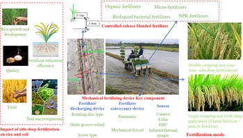
Rice is one of the most important food crops, with about 60% of the world's population using it as their staple food. As food demand is rapidly increasing with population growth, many agricultural producers are cultivating high-yield food crops that require large amounts of chemical fertilizers. However, the growth rate in food production is not proportional to that of chemical fertilizer use. Excessive chemical fertilizer input is a serious issue, as it not only increases agricultural production costs and wastes resources but also hardens cultivated land and acidifies the soil, reducing the yield potential of arable land. This can form a vicious circle where increasing amounts of chemical fertilizers are required to obtain the same crop yield. On the other hand, groundwater contamination, eutrophication, emission of greenhouse gases and air pollution are negative externalities deriving from the improper use of fertilizers. Therefore, fertilizer management is crucial for the economic and environmental sustainability of cropping systems. Rice side-deep fertilization is a fertilization management and technical system (Fig. 1) that can effectively improve fertilizer utilization efficiency, increase rice farming income and reduce environmental pollution compared with conventional fertilization methods. It is of great significance to the mechanization of rice production and the sustainable development of agriculture.
Side-deep fertilization technology of rice.

In conventional fertilization operations, a basal fertilizer is usually applied to the ground surface manually or with a fertilizer spreader when the ground is trimmed. Then, a soil preparation machine is used to mix the fertilizer and soil. After soaking the field and transplanting seedlings, topdressing with tiller fertilizer and panicle fertilizer is carried out. Conventional methods have a high labor intensity and may create an uneven fertilizer distribution that causes inconsistent nutrient absorption by rice seedlings, directly affecting the yield and quality of rice. Side-deep fertilization applies a basal fertilizer, tiller fertilizer and panicle fertilizer once or twice during the rice seedling transplanting stage at a position 3–5 cm away from the root and a depth of 5–8 cm. The number of required operations is reduced and fertilizer is applied at a certain distance from the roots to avoid root damage and burning of the seedlings. In addition, the fertilizer is covered by soil, which reduces losses due to drainage and improves utilization efficiency. The use of slow-release fertilizers can also enhance root vitality, ensuring that the rice will turn green and allow tillering without topdressing. Disease resistance and lodging resistance will also be enhanced.
Rice side-deep fertilization requires the use of a certain device. The operating environment of paddy fields is different from that of dry fields, so the traditional ditch discharging method does not work well in paddy fields. Water and mud will affect the discharge of fertilizer from the bellows of the application device. Therefore, side-deep fertilization devices have unique characteristics, and rice fertilization machinery is closely related to rice planting methods. One is the direct-seeded mechanized rice cultivation system used in Europe and America. A fertilizer machine performs fertilization operations or simultaneous spraying herbicide and fertilization. The second is a rice transplanting mechanized cultivation system used in China, Japan and South Korea. Rice is transplanted mechanically while side-deep fertilization is generally performed simultaneously. However, the degree of mechanization in rice side-deep fertilization techniques remains relatively low. To improve the level of mechanization and fertilizer utilization efficiency, side-deep fertilization equipment has been a focus of much research. Many mechanical devices have been independently designed and applied to rice production. However, many key technologies require further study. Because the efficacy of side-deep fertilization devices is significantly influenced by the fertilizer used, a special fertilizer is also required.
This article describes the fertilizer selection, the side-deep fertilization device and the impact on rice plants and soil in the rice side-deep fertilization technology. On this basis, future directions for the development of side-deep fertilization technology are proposed. It is expected to provide a reference for accelerating the promotion of side-deep fertilization technology and the optimization of key technologies.
Fertilizer types and modes for side-deep fertilization
Fertilizer types and characteristics
An appropriate fertilizer is key to the success of rice side-deep fertilization technology. Common fertilizers on the market mainly include organic fertilizers, micro-fertilizers (i.e., fertilizers containing trace elements), biological bacterial fertilizers and NPK (nitrogen, phosphorus and potassium) fertilizers. To reduce the number of fertilization instances required, slow- and controlled-release fertilizers are widely used in rice side-deep fertilization, which are classified according to various standards (Wu et al., Reference Wu, Wang, Ding, Tao, Gao, Li, Li, Liu and Li2021). For example, according to the preparation process, they can be divided into chemical modification, physical coating and biochemical inhibition types (Azeem et al., Reference Azeem, Kushaari, Man, Basit and Trinh2014). Slow- and controlled-release fertilizers can release nutrients at a suitable rate for the rice plant's requirements, which can reduce nutrient losses and improve fertilizer utilization efficiency and rice yield. The combination of controlled-release fertilizer and side-deep fertilization is key to reducing fertilization costs and increasing rice yield and production efficiency (Rahman et al., Reference Rahman, Haque and Khan2021) (Table 1).
Physical and chemical properties of NPK fertilizers
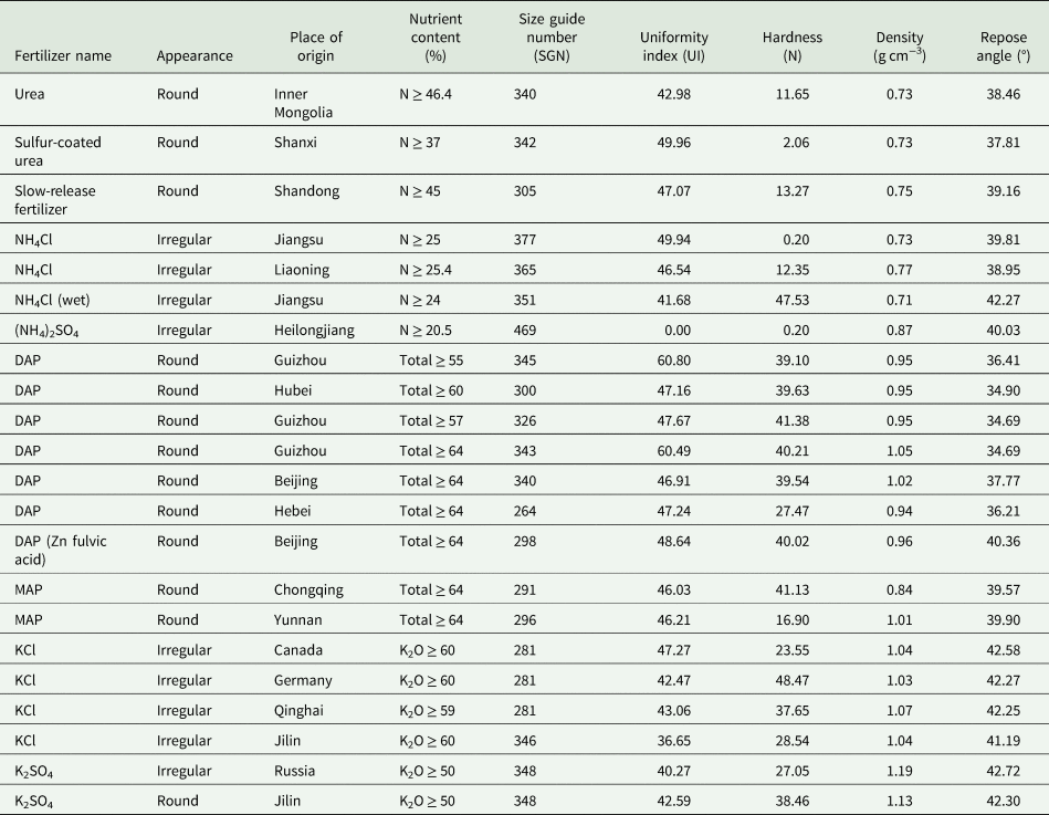
During the side-deep fertilization of rice, the ground is muddy and the working environment is humid. Therefore, the fertilizer requires a stable composition, good surface compression resistance, uniform particle size distribution and stable water absorption characteristics (Massoudi, Reference Massoudi2001; Linquist et al., Reference Linquist, Adviento-Borbe, Pittelkow, Van Kessel and Van Groenigen2012). Wang et al. (Reference Wang, Xiang, Zhang, Zhang, Wang and Chen2020) analyzed more than ten mainstream granular fertilizers, including slow- and controlled-release fertilizers, special rice fertilizers, compound fertilizers, blended fertilizers and controlled-release urea, and finding that their average particle size was 3–4 mm. The fertilizer with the best stability was ‘Heart to Heart’ controlled-release urea, which basically does not absorb water. The fertilizers ‘Yimaishi’, ‘Maoshi’, ‘Yara YARA’, ‘Wanli Shennong’, ‘Wolft Smart Film Star’, ‘Sinochem Fuwannong’, ‘Taiwan Qingshang Yicheng’ and ‘Liaoning Jinda Shengyuan’ all exhibited <8% water absorption over 24 h, which is relatively stable. The study noted that a fertilizer particle size of 2–5 mm is important for accurate fertilization. For blended fertilizers, Cao et al. (Reference Cao, Wang, Wang, Feng, Yan, Yuan, Du and Gao2019) pointed out that the average dominant particle size and angle of repose of raw material fertilizers are the main factors affecting nutrient separation during the application of blended fertilizers. When the size guide number of the raw material fertilizer is between 340 and 348, it is more suitable for blending, and the smaller the difference between the average dominant particle size, the more uniform the nutrient distribution. Selecting raw material fertilizers with a smaller angle of repose and reducing the difference between the angles of repose can reduce nutrient separation in blended fertilizers.
Fertilizer ratio and fertilization mode
Reasonable nutrient management improves fertilizer utilization efficiency and yield by meeting the nutrient requirements of plants throughout the growth period and ensuring the effectiveness of nutrients. Excessive nutrient supply wastes fertilizer, while insufficient supply decreases yield (Khanal et al., Reference Khanal, Anex, Gelder and Wolter2014). The combined application of nitrogen and other fertilizers (especially phosphorus and potassium fertilizers) can effectively increase rice yield and nitrogen fertilizer use efficiency (Sun et al., Reference Sun, Sun, Xu, Yang, Qing, Peng and Ma2013). This requires balancing the plant's nutrient demand and nitrogen supply (especially soil nitrogen nutrition and nitrogen fertilizer application) throughout the growth period (Cui et al., Reference Cui, Zhang, Chen, Miao, Li, Shi, Xu, Ye, Liu, Yang, Zhang, Huang and Bao2008). The absorption ratio of high-yield rice to N, P2O5 and K2O is 2:1:2.3 or 1:0.45:1.2. This is an indicator that reflects the balance between the three nutrients and is used to guide field fertilization (Ling, Reference Ling2007). However, for the subtropical region, Behera and Panda (Reference Behera and Panda2013) pointed out that N:P2O5:K2O as 2:1:1 is the most suitable fertilizer treatment for rice crop among studied treatments. Therefore, field fertilization needs to be done according to local soil characteristics and fertility, which are determined by soil testing and formula fertilization testing (Table 2).
Typical fertilization machinery

In addition to the combined application of nitrogen, phosphorus and potassium fertilizers, the combined application of organic–inorganic fertilizers, macronutrients and medium and trace elements is also a hotspot of research. The combined application of nitrogen, silicon, zinc and other trace fertilizers can delay leaf senescence, improve leaf photosynthetic characteristics and increase the nitrogen and crude protein contents of rice grains (Yamuangmorn et al., Reference Yamuangmorn, Insinjoy, Lordkaew, Dell and Prom-u-thai2020). The combined application of organic fertilizer and inorganic nitrogen fertilizer increases the net photosynthetic rate of rice functional leaves, promotes the absorption and utilization of nitrogen by rice, increases rice yield and improves rice quality and soil physical and chemical properties (Pan et al., Reference Pan, Zhou, Li, Smith, Li, Qiu, Zhang, Xu, Shen and Chen2009). Microbial fertilizers can increase the nitrogen utilization rate, thereby increasing yield using less fertilizer. As the amount of nitrogen application decreases, the nitrogen utilization rate increases (Chen et al., Reference Chen, Zhu, Lin and Zhang2010).
Conventional rice fertilization is generally based on a basal fertilizer, tillering fertilizer and panicle fertilizer used three to four times. Panicle fertilizers are divided into two types: flower-promoting fertilizer and flower-retaining fertilizer. Rice side-deep fertilization generally uses slow- and controlled-release fertilizer and deep burial strip application, which can reduce the number of fertilization instances required. Current fertilization modes mainly include ‘single-dose deep fertilization at transplanting with 100% controlled-release fertilizer’ and ‘deep fertilization of 70% controlled-release fertilizer and topdressing of 30% quick nitrogen’. In ‘single-dose deep fertilization at transplanting with 100% controlled-release fertilizer’, nutrients are applied to paddy soil once during machine planting, which saves labor. ‘Deep fertilization of 70% controlled-release fertilizer and topdressing of 30% quick nitrogen’ applies a conventional basal fertilizer and a tiller fertilizer to the paddy soil during machine transplanting, and artificial application of one topdressing according to the growth of the rice.
According to recent research, the fertilization mode should be determined according to the rice season and variety type (Wang et al., Reference Wang, Xiang, Zhang, Zhang, Wang and Chen2020). For double-cropping rice or single-cropping conventional rice with a short growth period, the yield difference between single and multiple fertilization is not obvious, and one-time side-deep fertilization can be used. For single-season rice with a long growth period, such as indica–japonica hybrid rice, the growth period is 140–165 days. The demand for nitrogen, phosphorus and potassium for rice growth is high and one-time fertilization often affects yield. Hence, ‘deep fertilization of 70% controlled-release fertilizer and topdressing of 30% quick nitrogen’ is recommended, which is consistent with the goals of obtaining large panicle and increasing the seed setting rate in single-cropping indica–japonica hybrid rice (Qin et al., Reference Qin, Yang, Sun, Xu, Lv, Dai, Zheng, Jiang and Ma2017; Huang et al., Reference Huang, Jiang, Liu, Yuan, Wang, Zhao, Wang, Huo, Xu, Dai, Zhang, Li and Liu2021). In addition, Corbin et al. (Reference Corbin, Orlowski, Harrell, Golden, Larry and Jason2016) pointed out that rice has produced optimum grain yields when fertilizer is applied with a split application.
Mechanical fertilizing device
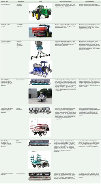
At present, rice planting methods include direct seeding and seedling transplantation. Among them, direct seeding machinery is mainly used in Europe and the Americas, with fertilizer spreaders used for fertilization (Crusciol et al., Reference Crusciol, Costa, Borghi, Castro and Fernandes2010). Seedling raising and transplanting machinery is mainly used in China, Japan and other Asian countries, and operates at the same time as fertilization. Fertilization machinery in European and American countries mainly includes centrifugal and pneumatic fertilizer applicators (Table 2). Centrifugal fertilizer applicators use a centrifugal discharging device to apply solid fertilizers and have the advantages of simplicity and low cost. Pneumatic fertilizer applicators mainly use liquid fertilizers and a high-speed fan. The airflow provides pressure to nozzles to achieve wide and efficient spreading, which has the advantages of covering a large working area and high efficiency. Representative machinery includes the SPW series fertilizer spreaders produced by Gamberini, Italy, and the Flexi Soil variable fertilizer planter produced by the Case Company. However, none of these fertilizing machines can achieve side-deep fertilization of rice.
Side-deep fertilization machinery is the basis of the side-deep fertilization of rice (Table 2). Japan has studied side-deep fertilization technology since the 1970s, showing that it saves fertilizer and increases yield. Japan is committed to developing related equipment suitable for the side-deep fertilization of rice. Japanese companies represented by Kubota, Iseki and Yanmar have designed and developed a series of rice side-deep fertilization machines. The supporting equipment for mechanical transplanting and side-deep fertilization has achieved product serialization and standardization (Yao-Ming et al., Reference Yao-Ming, Li-Zhang, Zhong-Ping and Ling-Li2005). Some well-known agricultural machinery companies in China and South Korea have conducted research and development into side-deep fertilization devices for rice. They have developed pneumatic type and screw-push-type side-deep fertilization devices that are matched with rice transplanters. The key components of rice side-deep fertilization machinery are the fertilizer discharging device and fertilizer conveying device. There are many types of fertilizer discharging devices, mainly including rotary disc, outer groove wheel and screw types. They are commonly used to discharge crystalline fertilizers, compound fertilizer granules and dry powdered fertilizers. For fertilizer conveying devices, there are mainly pneumatic and mechanical forced-feeding devices. Among them, pneumatic devices have lower requirements in terms of the surface performance of the fertilizer. Generally, ordinary compound fertilizers can also be used, but they often cause blockages that cause poor fertilizer discharge. Mechanical forced fertilizer conveying devices have a strong ability to actively discharge fertilizer but have high requirements for the physical properties of the fertilizer surface, especially the resistance to compression and fragmentation (Yang et al., Reference Yang, Yang and Li2003).
These types of equipment are mainly composed of a fertilizer box installed at the rear of the rice transplanter, a mechanically driven fertilizer discharge device and a conveying device near the transplanting mechanism. During normal operation, fertilizer from the fertilizer tank is uniformly and quantitatively discharged into the conveying device. An opener divides the mud to form grooves. The fertilizer is affected by wind (or mechanical thrust) and gravity. As the transplanter advances, the fertilizer will be evenly delivered to a designated position to the side of the seedlings, thereby completing side-deep fertilization. At present, such equipment can only achieve continuous and uniform fertilization in strips, which uses 20–30% less fertilizer than traditional manual fertilization methods. However, there are still some problems, such as the transplanter continuing to discharge fertilizer when it slips or turns around.
Key component-fertilizer discharging device
Rotating disc type
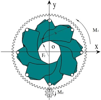
A rotating disc type fertilizer discharging device can discharge crystalline fertilizers, compound granular fertilizers and powdered dry fertilizers with good fluidity. This type includes centrifugal disc, scraper disc, impeller disc, etc. The disc and fertilizer guide cone are driven by a ground wheel through a chain and bevel gear and make circular motions relative to the fertilizer tank. When working, the fertilizer falls from the bottom of the fertilizer box into the fertilizer discharging disc. As the disc rotates to reach the scraper, fertilizer then rises along the rising angle of the scraper and, finally, falls into the soil through pipe. Patterson and Reece (Reference Patterson and Reece1962) first studied the movement of granular fertilizer on the disc, which laid the foundation for the construction of a mathematical model of the disc fertilizer applicator. Villette et al. (Reference Villette, Cointault, Piron and Chopinet2005) studied the motion of fertilizer particles on a rotating disc and analyzed the ratio of the horizontal radial component to the horizontal tangential component of the velocity when the fertilizer particles leave the rotating disc. This provided a theoretical basis for the design of later disc fertilizer applicators. Cool et al. (Reference Cool, Pieters, Mertens, Hijazi and Vangeyte2014) constructed a trajectory model of fertilizer particles after they leave the disc and studied the influence of their rotation on their trajectory in the air and the position of the landing point. The results show that the rotation of fertilizer particles after leaving the horizontal disc has an important influence on the position of the drop point. Jin-Feng et al. (Reference Jin-Feng, Guan-Bao, Wu-Xiong, Jin-Wu, Dong-Wei and Bo-Wen2018) and others designed a blade-type fertilizer regulation mechanism. The friction between the fertilizer particles and leaves was analyzed. Each blade is only subject to the pressure FN of the fertilizer particles and the frictional force Ff between the blades during operation (Fig. 2). Further, when the equipment is properly calibrated, external factors play a far more important role (Simon et al., Reference Simon, Jan, Joris, Jan, Koen, David, Tim and Jürgen2016). Hofstee and Huisman (Reference Hofstee and Huisman1990) pointed out that the coefficient of friction, the aerodynamic resistance, the particle size and particle size distribution are most important, because they affect the diffusion mode to a great extent. Marcello et al. (Reference Marcello, Pietro and Paolo2013) found that the terminal velocity of fertilizer particles is related to measurable physical properties (mass, shape, size) of the product, and physical features of the individual particles determine the distribution pattern.
Force diagram of blades in the XOY plane.

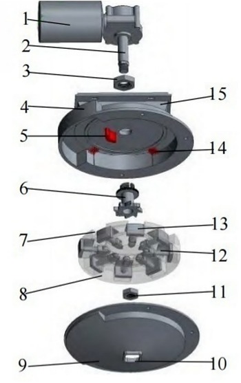
Most of the side-deep fertilizer applicators produced by Yanmar and other companies adopt a horizontal disc structure. By changing gear wheels with different apertures, the gear speed is adjusted to adjust the fertilizer rate. The fertilizer stability and uniformity of application are better, but the structure is more complex. They have high installation accuracy, difficult maintenance and relatively high fertilizer requirements, so need to be used in conjunction with a specific fertilizer type. In order to improve the versatility of the device, Jin-Feng et al. (Reference Jin-Feng, Wen-Hu, Wu-Xiong, Jin-Wu, Qi and Xin-Sheng2021) designed a disc ejection-type side-deep fertilization device that can adjust the fertilization rate by changing the effective working length of the fertilizer tank (Fig. 3). The process of filling and discharging the fertilizer disc was simulated and analyzed. It was found that in the process of filling, when the rotation speed of the fertilizer disc is 5 r min−1, the fertilizer particles gather on the fertilizer tank for too long. This intensifies the wear caused by fertilizer particles to the housing of the fertilizer discharging device and increases the rate of fertilizer particle breakage. As the rotation speed of the fertilizer disc increases, the friction and shear forces of the fertilizer particles are significantly reduced. In the process of discharging fertilizer, when the speed of the discharging disc is 5 r min−1, the rotation angle γ of the fertilizer particles discharged from the fertilizer tank to the lower shell varies in the range of 9–46°. As the rotation speed increases, the rotation angle γ increases. When the speed of the fertilizer disc is 65 r min−1, most of the fertilizer in the fertilizer tank will hit the shell at the end of the fertilizer zone before sliding down the fertilizer mouth along the shell. At this time, the maximum range of variation in turning angle γ is already greater than the central angle corresponding to the fertilizer discharging area, which is not conducive to fertilizer discharge. Therefore, the best working speed of the fertilizer discharging disc is 10–60 r min−1.
Disc ejection type fertilizer discharging device: (1) drive motor, (2) fertilizer shaft, (3) fertilizer fastening nut, (4) upper shell body, (5) curved convex, (6) fertilizer adjustment device, (7) fertilizer trough, (8) fertilizer disc, (9) lower shell body, (10) fertilizer outlet, (11) fastening nut, (12) pressure spring, (13) fertilizer ejector pin, (14) fertilizer scraping brush, (15) fertilizer inlet.

Outer groove wheel-type fertilizer discharging devices
Outer groove wheel-type fertilizer discharging devices are the most common fertilizer discharging devices on the market (Fig. 4) (Zuo, Reference Zuo2016). They have a simple structure, are suitable for loose chemical fertilizers and granular compound fertilizers, and have good fluidity. During operation, the grooved wheel (which has a certain shape groove on the surface) rotates with the fertilizer shaft, and the rotating outer groove wheel continuously discharges the fertilizer in the groove, which falls by gravity. At the fertilizer outlet, it flows into the mud ditch opened by the opener through the corrugated pipe. Outer groove wheel-type fertilizer discharging devices can be divided into fixed and mobile types according to whether the grooved wheel can move axially. Among them, the mobile outer groove wheel-type fertilizer discharging device can more easily adjust the rate of application. However, when applying powdery and relatively moist fertilizers, it is prone to clogging and other phenomena.
Four different types of outer groove wheel fertilizer discharging devices.

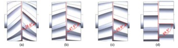
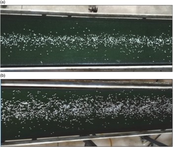
The shape, outer diameter, number of grooves and speed of the outer sheave are important factors affecting the rate and precision of fertilizer application. The traditional outer grooved-wheel device is mainly equipped with straight grooves, and the particles are discharged from the exit under free-flow condition. More particles are discharged when the grooved wheel turns to the groove, while fewer particles are discharged when the grooved wheel turns to the ridge. This phenomenon is particularly obvious at low speeds. At the same time, during the movement, the particles in the grooved wheel are subjected to a large force, which easily breaks the particles or causes the grooved wheel to get stuck, which affects the precision of fertilization (Arif, Reference Arif2010). When the outer groove wheel is a spiral groove wheel, as the fertilizer wheel rotates, granular fertilizer is continuously discharged along the rotation direction of the groove, which helps to improve the uniformity of fertilizer discharge (Leng et al., Reference Leng, Li, Zhang and Ren2018). Du et al. (Reference Du, Yang, Xia and Li2020) adopted a staggered spiral tooth design and simulated fertilization performance using a discrete element model (DEM). A spiral angle of 47.5° was considered reasonable for an outer groove wheel fertilizer applicator (OGWFA). A 47.5° spiral tooth has a lower coefficient of variation and a smaller fertilizer distribution width than a straight tooth outer groove wheel fertilizer discharging device (Figs. 5 and 6).
Angles of helical teeth used in simulations: (a) 28.6°, (b) 47.5°, (c) 69.9°, (d) 89.5°.

Fertilizer distribution in laboratory tests with a 30 mm working length and 20 rpm rotational speed for (a) an OGWFA with 47.5° helical teeth, (b) an OGWFA with straight teeth.

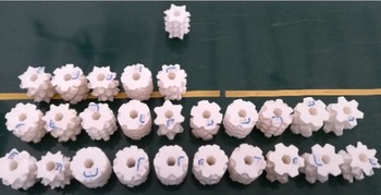
Sugirbay et al. (Reference Sugirbay, Zhao, Nukeshev and Chen2020) studied a pin-roller device with different α angles, pin heights, β angles and radii between two pins (Figs. 7 and 8). The design evaluated fertilizer distributions under 25 pin roll configurations at three speeds. Indoor experiments showed that different pin roller characteristics have a significant impact on the uniformity of fertilizer distribution and discharge. At all speeds of the device, the flow of the new pin-roll device was not lower than that of the device with the outer groove wheel structure, but the coefficient of variation of the flow of the pin roll was larger than that of the outer groove wheel structure at lower speeds. However, at higher speeds, there was no significant difference in the coefficients of variation of the devices.
Parameters of the roller pin: (a) n = number of right and left entry lines, β = angle between the vertical axis and right and left entry lines, (b) h = height of the roller pin and α = angle between the hexagonal polygon and pin inclination.

Twenty-five 3D-printed pin-rollers with different parameters.

The diameter of the outer groove wheel is also an important factor affecting the rate and precision of fertilizer application. When the rate of fertilization is constant, the diameter of the fertilization wheel is too large, the speed and the effective working length are reduced correspondingly and the uniformity of fertilization will decrease. As the diameter of the fertilizer wheel becomes smaller, the number of uniformly distributed slots on it will decrease accordingly. To meet a certain range of fertilizer application adjustment, the speed of the fertilizer wheel must be increased. When the rotation speed of the fertilizer wheel is too large, not only is the wear rate of granular fertilizer increased, the time taken for the fertilizer wheel to pass through the fertilizer filling area will be shortened, and the granular fertilizer filling factor in the groove will decrease accordingly, affecting the stability of fertilization. However, some studies have pointed out that higher fertilizer wheel rotation speeds improve the uniformity of fertilization (Jin-Feng et al., Reference Jin-Feng, Guan-Bao, Wu-Xiong, Jin-Wu, Dong-Wei and Bo-Wen2018). Sun et al. (Reference Sun, Chen, Duan, Liu and Zhu2020) used the rate of fertilization as an indicator to explore the best working parameters for an OGWFA (Figs. 9–11). Simulation and experimental results show that under static and dynamic conditions, the force on the fertilizer particles first decreases and then increases with increases in the helix angle. Under static conditions, the discharge speed of the fertilizer particles first increases and then decreases with increases in the helix angle, and then fluctuates within a small range. Under dynamic conditions, the discharge speed of the fertilizer particles first decreases and then increases with increases in the helix angle, and finally fluctuates in a small range. The interaction between the radius of the outer groove wheel and its speed has a significant effect on the rate of fertilizer. The groove radius vs speed, the groove radius and the inclination angle of the fertilizer feeder have significant effects on the coefficient of variation of fertilizer application. The optimal working parameters are: groove radius = 13.5 mm, helix angle = 62°, rotation speed = 29.4 r min−1 and fertilizer feeder inclination angle = 5°.
Helical grooved wheel.

Variations in circumferential force FT and axial force FZ with helix angle.

Position of maximum force.

Jin-Feng et al. (Reference Jin-Feng, Guan-Bao, Wu-Xiong, Jin-Wu, Dong-Wei and Bo-Wen2018) analyzed a theoretical fertilizer supply model for an outer groove wheel. A cross-section of the grooved section of an outer groove wheel-type fertilizer discharging wheel is shown in Figure 12. The groove section has an ‘L’ profile and is composed of a normal line segment, a tangential line segment and a circular arc with a central angle of 90°. The radius r of the arc is greater than the radius of the granular fertilizer. The filling cross-sectional area S 0 of a single ‘L’-shaped fertilizer groove is the sum of the spherical cap area S 1, the right-angle trapezoidal area S 2, the spherical cap area S 3, the triangular area S 4 and the sector area S 5. The formula is as follows:

where,


where φ, ψ is the central angle (°); q is the tangential line segment length (mm); p is the length of a normal line segment (mm) and r is the circular arc radius (mm).
Schematic diagram of the fertilizer wheel filling area.

According to the working process of these devices, when the fertilizer discharging wheel rotates, the granular fertilizer that enters the groove is discharged through the opening under the force of the grooved teeth of the discharging wheel, which is called a forced layer. A layer of granular fertilizer with a thickness of C 0 on the outer edge of the fertilizer wheel is intermittently squeezed by other granular fertilizers and the protruding parts of the grooved teeth. It is discharged at a relatively low speed between the outer edge of the fertilizer wheel and the brush, and the discharge is called the driving layer (Pan et al., Reference Pan, Zhao, Jin, Qu and Tian2016). Then, the amount of fertilizer discharged per turn of the fertilizer wheel is:

where q 1 = λσL 0ZS 0; q 2 = 2πσRL 0C n, where λ is the filling coefficient of granular fertilizer in the groove; σ is the volume-weight of granular fertilizer (kg m−3); and C n is the driving layer characteristic coefficient; L 0 is the effective working length of groove.
Screw-type fertilizer discharging devices
Screw fertilizer discharging devices are used in many rice fertilization machines. They have the advantages of a simple structure, closed conveying environment, adjustable conveying volume and stable single-ring conveying volume. They are a forced conveying method (Jiang et al., Reference Jiang, Chen, Yan, Mo and Yang2019). However, in the application process, the fertilizer storage space formed between the spiral blade and spiral sleeve differs when the rotation of the end surface of the blade of the fertilizer outlet goes to a different position. Fertilizer particles are differently blocked by spiral blades and spiral sleeves, resulting in pulsation of fertilizer particles and periodic changes in application rate. This restricts their application in fine feeding devices (Anton et al., Reference Anton, Hubert and Georg2007; Yuan et al., Reference Yuan, Li, Ye and Zhou2020). Therefore, reducing the pulsation phenomenon in screw-type fertilizer mechanisms has become a research focus.
Structural parameters, such as the length and angle of the fertilizer discharge opening, and the pitch and outer diameter of the screw fertilizer discharge device, are important influences on the fertilizer application rate (Fig. 13) (Kretz et al., Reference Kretz, Callau-Monje, Hitschler, Hien and Raedle2015). Yang et al. (Reference Yang, Fang, Luo, Li and Ye2020) studied the influences of the length and angle of the fertilizer opening on the uniformity of fertilizer application at a spiral speed of 30 r min−1. It was found that the primary and secondary factors affecting the performance of the screw fertilizer discharging device were the length and angle of the discharge port. The two have very significant impacts on the stability and uniformity of fertilizer discharge. The best application effect was achieved at a 135° angle and length of 60 mm (Figs. 14 and 15). In addition, the screw conveying mechanism was optimized by adding a double helix structure and leaving an empty pitch. The researchers analyzed the relevant parameters of the two-stage spiral fertilizer device by establishing a mathematical model of the fertilizer discharge volume of the fertilizer discharge screw. It was determined that the device had a good discharging effect and good adaptability to various forms of fertilizer, so that material discharge pulsation was reduced (Chen et al., Reference Chen, Luo, Wang, Zhang, Hu, Yang, Zeng, Zang, Wei and Zheng2015). However, due to the need for additional devices, it is not conducive to application to small machines (Wang et al., Reference Wang, Mao and Liu2005). For unloading speed, it directly depends on the rotating speed of the discharging devices (Camacho-Tamayo et al., Reference Camacho-Tamayo, Barbosa, Pérez, Leiva and Rodríguez2009), and is directly related to the material's density (Walker et al., Reference Walker, Grift and Hofstee1997). At the same time, it is affected by the particle size, repose angle, bulk density, surface roughness and moisture content of the fertilizer (Grift et al., Reference Grift, Walker and Hofstee1997; Aphale et al., Reference Aphale, Bolander, Park, Shaw, Svec and Wassgren2003).
Different screw shapes for investigating slide-in behavior: (a) reference screw, (b) conical threads, (c) variable thread pitch, (d) variable screw shaft diameter.

Schematic diagram of a screw fertilizer discharging device: (1) drive motor, (2) coupling, (3) feeding inlet, (4) screw, (5) screw shell, (6) discharge port, (7) concentrator.

Simulation of transient fertilizer discharge with the screw blade at different phase angles: (1) screw, (2) spiral casing end face.

In side-deep rice fertilization devices, because the spiral pulsation cycle is quite complicated, reducing the pulsation cycle can reduce the size of the overall pulsation, although it increases the complexity of the system. Therefore, a screw fertilizer discharging device is often combined with other types of discharge devices. A screw fertilizer discharging device uniformly conveys fertilizer to the outer groove wheel or rotary disc discharging device for secondary distribution. Finally, fertilizer is forced to the outlet by pneumatic conveyance or a mechanical device.
Key components of fertilizer conveyance devices
Pneumatic
Pneumatic fertilization devices use positive air pressure to convey auxiliary fertilizer. The fertilizer particles are discharged by the device carried by flowing gas and fall into the grooves drawn by the opener along the direction of the pipeline under the dual action of airflow and own gravity. This method can effectively prevent problems such as poor flow in the fertilizer pipeline caused by deliquescence of fertilizer particles and clogging. This is the key to achieving stable fertilization (Zuo et al., Reference Zuo, Wu, Fu, Li, Wei and Zhao2016). Pneumatic fertilizer conveying devices are mainly composed of a fan, a fan speed switch, an air supply pipe, a venturi pipe (Fig. 16) and a corrugated conveying pipe. Among them, the venturi pipe is a key component of the air delivery system, and includes a fertilizer inlet, air inlet, contraction section, throat, diffuser and air outlet. The lower fertilizer port, air supply pipe and fertilizer pipe of the discharging device are respectively connected with three ports in the venturi pipe. During operation, the air flow from the fan at the front end of the air delivery system passes through the inlet cylindrical section and through the cylindrical throat at high speed. Negative pressure is formed at the feed inlet, so that there is no gas leakage from the feed port (Hu, Reference Hu2013). The fertilizer particles are smoothly dropped into the fertilizer pipeline and fully mixed with the air flow, and then transported through the pipeline to the groove drawn to the side of the seedlings.
Venturi structural diagram: (1) inlet cylindrical section, (2) conical contraction section, (3) feed inlet, (4) cylindrical throat, (5) conical diffusion section, (6) export cylinder section.

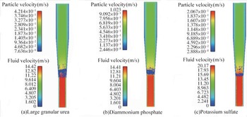
Pneumatic fertilizer-conveying devices mix granular fertilizer with high-speed airflow to form a gas–solid mixed flow. In-depth research on the pneumatic conveyance of solid particles has been made, with simulations considering particle velocity and acceleration, as well as the deposition characteristics of solid particles in the conveyance pipeline (Kumar and Durairaj, Reference Kumar and Durairaj2000; Li et al., Reference Li, Webb, Pandiella, Campbell and Dyakowski2005; Wang et al., Reference Wang, Williams, Illiams and Jones2017; Yatskui et al., Reference Yatskui, Lemiere and Cointaulf2017; Tripathi et al., Reference Tripathi, Santo, Kalman and Levy2018). In actual operations, the speed of the fan is often fixed to maintain good continuity and stability of fertilization at the minimum or maximum rates. Previous studies have shown that when the wind speed from the fan is 18–35 m s−1, the fertilizer particles are evenly distributed, which is beneficial to the accuracy and uniformity of fertilization (Li-Wei et al., Reference Li-Wei, Zhi-Jun, Xiao-Ou, Xiao-Fei, Pei and Guang-Wei2018; Yang et al., Reference Yang, Li, Li, He, Wang and Lu2019). In terms of fertilizer materials, Wen et al. (Reference Wen, Jia, Zhang, Yuan, Wang and Chen2020) tested three granular fertilizers—large urea, diammonium phosphate and potassium sulfate (Fig. 17)—and used the Lagrangian model in a gas–solid two-phase-flow coupled simulation. It was found that the suspension speed of the particle group decreases with increases in the volume fraction. At different volume fractions of particle fertilizer, the relative error between the simulation results and test results was approximately constant. This result provides a basis for the design of air-fed fertilizer conveyance mechanisms.
Suspension position and velocity flow field distribution of different fertilizer particle groups.

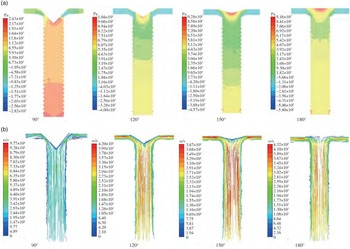
Yang et al. (Reference Yang, Li, Li, He, Wang and Lu2019) coupled DEM-computational fluid dynamics simulation to perform numerical analysis of particle movement in a pneumatic centralized fertilizer distribution device (Figs 18–20). By studying the influence of the cone angle of the screw cap and the diameter of the corrugated pipe of the centralized fertilizer distribution conveying device on the air pressure, wind speed and movement characteristics of the fertilizer particles, the optimal structural parameters were determined. Based on this structure, the influences of inlet wind speed and fertilization rate on the uniformity of fertilizer distribution were further studied. It was found that the cone angle of the distributor screw cap and the diameter of the bellows significantly affect the movement of fertilizer particles, airflow velocity and the pressure field distribution. At a distributor screw cap cone angle of 120° and corrugated pipe diameter of 80 mm, the fluidity and uniformity of the two-phase airflow and fertilizer in the fertilizer separation device were optimal.
Pressure cloud charts and velocity distributions of fertilizer distribution devices with different screwing caps: (a) pressure cloud charts, (b) velocity distributions.

Distributions of fertilizer particles in fertilizer distribution devices with different screwing caps.

Distributions of fertilizer particles in fertilizer distribution devices with different bellows.

Mechanical forced
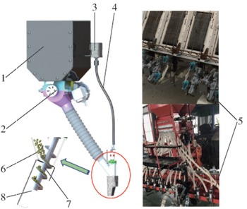
Mechanical forced fertilizer conveying devices usually use a screw conveyor or a spiral steel wire to convey fertilizer. Fertilizer particles discharged from the device fall into the groove drawn by the opener along the direction of the pipeline under the combined action of screw thrust and gravity. The whole process is usually divided into three stages (Wei et al., Reference Wei, Qi, Jiao, Shi and Jian2020). As shown in Figure 21, in the filling stage, with rotation of the screw conveyor, the flow of fertilizer particles does not accumulate, so the fertilizer enters the screw conveyor under its own gravity and is brought into the components. In the conveying stage, the fertilizer is forcedly pushed by the spiral surface of the screw conveyor and moved to the bottom of the tee. The lower surface of the spiral surface of the screw conveyor does not form a large effective shear force area, and the effective friction area is relatively small. In the discharging stage, the fertilizer particles are forced out of the screw conveyor under the thrust of the lower surface of the screw conveyor. The force on the fertilizer mainly comes from the lower surface of the screw conveyor. Structural parameters such as the diameter, speed and pitch of the screw-type forced fertilizer delivery device are important influences on application rate. Wei et al. (Reference Wei, Qi, Jiao, Shi and Jian2020) considered that the influences on the fertilizer delivery performance index, from large to small, are the speed, pitch and diameter, and established regression equations between the fertilizer delivery performance index and each factor. The optimal combination of working parameters was determined to be a screw conveyor speed of 120.09 r min−1, diameter of 23.90 mm and pitch of 21.54 mm. Unfortunately, there is still little research on the mechanism of screw-type forced fertilizer conveying devices, as non-forced types are the usual focus (Fig. 22).
Force analysis of fertilizer particles during forced fertilizer delivery: (a) establishment of mechanical forced fertilizer component: (1) bearing, (2) screw conveyor, (3) opener, (4) tee, (b) initial force analysis of fertilizer particles, (c) force analysis of fertilizer particle, (d) force analysis at moment of fertilizer particle sliding.

Sensors
In order to improve the fertilizer utilization efficiency of rice side-deep fertilization operation machinery, variable fertilization technology is widely used. Currently, variable fertilization is mainly achieved in two ways, based on (1) fertilization decision data of a variable fertilization prescription map (Bacenetti et al., Reference Bacenetti, Paleari, Tartarini, Vesely, Foi, Movedi, Ravasi, Durello, Ceravolo, Amicizia and Confalonieri2020), or (2) fertilization data calculated by real-time sensors (Table 3) (Wu and Song, Reference Wu and Song2021). The operating machinery applies a specified amount of fertilizer within a certain area based on the fertilization data (Zhao et al., Reference Zhao, Xun, Wang, Chen, Pan and Meng2003; Fu et al., Reference Fu, Meng, Huang, Chen and Wang2008). Variable-rate fertilization technology has been widely used in dryland agricultural production in European and American countries and has been commercialized (Birrell and Hummel, Reference Birrell and Hummel2001; Burks et al., Reference Burks, Shearer, Heath and Donohue2005; Kodaira and Shibusawa, Reference Kodaira and Shibusawa2013; Pennock et al., Reference Pennock, Bedard-Haughn, Kiss and Van2014; Rudolph et al., Reference Rudolph, Wongleecharoen, Lark, Marchant, Garre, Herbst and Weihermiiller2016). For example, Ag-Chem has conducted a lot of research on variable fertilization and has developed many mature products. Their variable fertilization system can carry out variable fertilization control of solid and liquid fertilizers. At the same time, variable fertilization can be controlled independently for different fertilizers according to a pre-loaded variable fertilization decision prescription map. The ACCU-PLANT programmable planter fertilization control system produced in Iowa, USA, is mainly composed of a hydraulic transmission system, a ground speed sensor and a microprocessor. The fertilizer discharging device is driven by a hydraulic motor and the controller mainly adjusts the fertilization amount by changing the motor speed to achieve variable fertilization. The ZA-M series suspended variable spreader and ZA-B series traction variable spreader developed by Amazone (Germany) are equipped with Amazon ISOBUS service terminal communication equipment and a variety of agricultural sensors. It can collect crop growth characteristics in real-time, quickly calculate the suitable fertilization amount for crop growth in a unit area and control the working speed and width of the centrifugal fertilizing disc through an independent hydraulic drive device to achieve precise variable fertilization. In addition, there are the Flexi Soil variable fertilization planters from the Case Company, USA (Sudduth et al., Reference Sudduth, Drummond and Kitchen2001; Alchanatis et al., Reference Alchanatis, Ridel, Hetzroni and Yaroslavsky2005; Kim et al., Reference Kim, Kim, Ryu and Rhee2008; Cui et al., Reference Cui, Zhao, Li, Zhang, Ren and Bai2010; Anh et al., Reference Anh, Gomi, MacDonald, Mizugaki, Van Khoa and Furuichi2014) (Fig. 22).
Structural diagram of mechanical forced fertilizer components: (1) Fertilizer box, (2) Electric fertilizer discharging device, (3) Drive motor, (4) Flexible shaft, (5) Forced fertilizer discharging parts, (6) Tee pipe, (7) Screw conveyor, (8) Ditch opener.

Comparison of the advantages and disadvantages of different sensors

In recent years, variable fertilization technology has also received increasing attention in Asia, and precision agriculture has developed rapidly in China, Japan, South Korea and other countries. The JKB series self-propelled paddy field variable spraying fertilizer applicator produced by Japan Iseki Agricultural Machinery Co., Ltd. integrates variable spraying and fertilizer spreading systems. It performs real-time collection of information on soil nutrients and crop characteristics through a variety of agricultural sensors, and adjusts the amounts of spray and fertilizer through a controller, making it suitable for variable fertilization operations in each rice growing period. Shi et al. (Reference Shi, Chen, Wang, Morice, Li and Ding2018) and Zuo (Reference Zuo2016) developed a variable rice fertilizer applicator using speed sensors, global positioning system), near-Earth spectrum detection technology and fuzzy PID control technology. The fertilization amount is adjusted in real-time according to the sensor information to carry out precise side-deep fertilization and improve fertilization uniformity. However, its actual application effect still needs further verification.
Japan has done unique research on variable side-deep fertilization technology for rice, especially for use in small-scale plots. However, current research on the variable fertilization of rice mainly focuses on the growth of rice seedlings and, due to the constraints of its sensors, this technology has not been widely applied.
Impact of side-deep fertilization on rice and soil
The rational use of side-deep fertilization technology is key to improving fertilizer utilization efficiency and improving rice quality and yield. Therefore, understanding its effects on rice, fertilizer and soil is extremely important for its application and promotion. Next, this study elaborates on these effects as well as the influences on soil microorganisms.
Effects of side-deep fertilization on rice growth and development
Compared with conventional fertilization methods, side-deep fertilization can increase the nitrogen concentration at the roots and meet the nutrient requirements of the rice seedling stage. At the same time, side-deep fertilization provides a kind of asymmetric partial fertilization of the rhizosphere of crop seedlings. Nutrients are accurately delivered to the root zone via machinery, which increases the concentration of nitrogen fertilizer by about five times compared with that of the surface layer. However, this local nutrient supply will cause an uneven distribution of soil nutrients. Wang et al. (Reference Wang, Tang and Shen2013), Jing et al. (Reference Jing, Zhang, Rengel and Shen2013), Li et al. (Reference Li, Zhang and Shen2012) and others believe that the local nutrient supply is conducive to root proliferation and can change the root morphology by increasing the root length, lateral root density and fine root ratio. It has a stronger effect on crop growth and nutrient absorption in the early growth period than in the later period. However, a local nutrient supply may cause uneven rice growth. Wang et al. (Reference Wang, Wu, Hu and Chen2002) studied the effects of NO3− on the development of lateral rice roots and their nitrogen uptake through vermiculite culture experiments under dry conditions. They found that a local supply of NO3− promotes the growth of lateral rice roots. In addition, side-deep fertilization promotes the absorption of fertilizers under adverse conditions, such as low temperatures, compared with conventional fertilization. The maximum tillering stage of rice appears earlier and the number of divisions occurring within 30 days of transplanting is as much as 30% greater than that of conventional fertilization. It can increase low node tillers, reduce the number of ineffective tillers, advance the heading date and ensure the safe maturity of rice. If fast-acting fertilizer is used for side-deep fertilization, the nitrogen concentration in the soil layer will be reduced 30 days after rice transplanting, avoiding lodging caused by overgrowth, fully reducing ineffective rice tillers, and promoting early rice development (Zhu et al., Reference Zhu, Xiang, Zhang, Zhang, Zhu and Chen2019b). If side-deep fertilization is done with a controlled-release fertilizer, nutrients can be released slowly over the entire growth period, and can release nutrients at a suitable rate for the rice plant's requirements (Xiao-Dan et al., Reference Xiao-Dan, Ya-Liang, Yu-Ping, Jing, Yi-Kai, De-Feng and Hui-Zhe2021). But there are also studies that point out (Lyu et al., Reference Lyu, Yang, Pan, Zhang, Cao, Ulgiati, Wu, Zhang, Wang and Xiao2021), since a controlled-release fertilizer has a slow release of nutrients in the early stage of rice growth, it is not conducive to rice tillering. A mixed treatment of slow-release nitrogen fertilizer and urea can effectively increase rice yield and nitrogen fertilizer utilization, and has the best economic benefits.
Relationship between side-deep fertilization and rice yield
The yield of rice is composed of four parts: the number of panicles, the number of spikelets per panicle, the seed setting rate and the thousand-grain weight (Pan et al., Reference Pan, Zhao, Jin, Qu and Tian2016). Predecessors agree that increasing the number of spikelets in the population (number of panicles × number of spikelets per panicle) is the key to increasing rice yield while ensuring the stability of the seed setting rate and thousand-grain weight (Huda et al., Reference Huda, Gaihre, Islam, Singh, Islam, Sanabria, Satter, Afroz, Halder and Jahiruddin2016; Xie et al., Reference Xie, Shan, Wang, Cao, Chen, Huang and Zou2019). Reasonable fertilization methods can promote the formation of effective tillers, so that rice has a higher population of spikelets, thereby forming a more reasonable population (Zhang et al., Reference Zhang, Wu, Dai, Huo, Xu, Gao, Wei, Duanmu, Sun, Zhao, Sha, Zhou, Li, Xiao, Wang and Wu2010). Compared with traditional fertilization methods, side-deep fertilization can promote rice tillering and reduce the production of ineffective tillers, ultimately increasing the number of panicle per square meter and the yield (Yang et al., Reference Yang, Du, Wu, Liu, Wang and Zhu2006). Compared with surface application, deep layer fertilization can accurately transport nutrients to the roots, thereby reducing nitrogen losses caused by ammonia volatilization and surface runoff (this is the most important mechanism of nitrogen loss in low yield areas of rice) (Vibhu et al., Reference Vibhu, Singh, Patil, Magre, Shrivastava, Mishra, Das, Samadhiya, Sanabria and Diamond2008; Roberts et al., Reference Roberts, Norman, Ross, Slato and Wilson2012; Atique-ur et al., Reference Atique-ur, Farooq, Nawaz and Ahmad2014). This gives rice seedlings sufficient nutrients in the early growth stage, thereby promoting early and rapid growth of rice tillers and increasing yield (Wu et al., Reference Wu, Li, Li, Liu, Jiang and Li2017). Huang (Reference Huang2021) studied the impacts of side-deep fertilization methods on rice yield and found that it increases yield by producing more panicle and population spikelets. The highest yield was obtained with a 70% basal fertilizer side-deep application + 30% panicle fertilizer because this treatment provides a topdressing panicle fertilizer during the top three-leaf period. In the top three-leaf stage, rice is in the young panicle differentiation stage. Adding panicle fertilizer during this stage prevents the leaves from premature aging, promotes the normal metabolism of leaves during the filling stage (Ishfaq et al., Reference Ishfaq, Akbar, Zulfiqar, Jabran and Farooq2021) and ensures that the rice has high source-sink activity (Zhu et al., Reference Zhu, Li, Chen, Wu, Ouyang, Yu, Huang and Luo2020). Moreover, it can also protect the tillers and increase the panicle, thereby increasing the number of panicle and the rate of panicle formation. Increasing spike fertilization can also promote the differentiation of spikelets and reduce the degradation of spikelets, thereby increasing the number of spikelets in the population, increasing the seed setting rate and thousand-grain weight and, ultimately, increasing yield (Ke et al., Reference Ke, Jun, Hong-Cheng, Jin, Bao-Wei, Zhong-Yang, Qi-Gen, Hai-Yan, Hui, Pei-Jian, Fei-Hu, Da-Shan, Zhong-Ping and Guo-Liang2014; Liu et al., Reference Liu, Fan, Zhang, Chen, Li and Cao2015). Treatment with 70% basal fertilizer side-deep application + 30% panicle fertilizer can significantly increase the nitrogen content in the root area of rice seedlings in the early growth stage so that the rice has enough nutrients to obtain a larger population, thereby increasing yield (Ding et al., Reference Ding, Zhao and Wang2003). Zhu et al. (Reference Zhu, Chen, Zhang, Xiang, Zhang, Yi and Zhu2019a) and Alimate et al. (Reference Alimate, Fofana, Sansan, Ebenezer, Robert and Opoku2015) also showed that side-deep fertilization can increase yield, mainly because it increases the number of effective panicles and the total number of spikelets. This trend was shown in rice in different seasons. In the panicle differentiation stage and full panicle stage, nitrogen accumulation, SPAD value and dry matter accumulation were significantly higher with controlled-release fertilizer combined with side-deep fertilization. This combination is considered effective in increasing rice yield and nitrogen utilization.
Relationship between side-deep fertilization and rice quality
The main factors affecting the cooking and eating qualities of rice are the amylose and protein contents, which are mainly controlled by genetics. However, as shown in Figure 23, starch content is also greatly affected by external environmental factors such as nutrients (Zhang et al., Reference Zhang, Guo, Blennow and Zorb2021). In particular, the application of nitrogen fertilizer has an important role in promoting rice quality (Ji et al., Reference Ji, Zhang, Dai, Wang, Tan, Zhang and Zhao2011), it can increase the protein content or change the amylose content in the rice grain (Parkash et al., Reference Parkash, Bhadoria, Amitava and Rakshit2002; Champagne et al., Reference Champagne, Bett-Garber, Grimm and McClung2007). Studies have shown that surface fertilization results in nutrient losses and low protein contents, which reduce rice yield. Therefore, surface fertilization is not the best fertilization method for high-quality rice production. Side-deep fertilization provides effective nutrients to the rice root system and promotes early development, while late top dressing promotes the establishment of a quality framework. At the same time, side-deep fertilization can reduce diseases and insect pests, and produce good-quality rice (Wopereis-Pura et al., Reference Wopereis-Pura, Watanabe, Moreira and Wopereis2005; Liu et al., Reference Liu, Li, Wang, Zhao, Chen, Hong and Zhou2014). According to related measurements, the polished rice rate and brown rice rate can be increased by 2.5 and 3.2%, respectively, and the cooking and eating values can be increased by 10% compared with conventional fertilization. Compared with conventional nitrogen fertilizer, the one-time application of an equivalent amount of slow/controlled-release compound fertilizer not only increases the rice heading rate and setback but also helps reduce the chalky grain rate (Yu et al., Reference Yu, Hu, Wang, Chen, Dong and Wu2016). However, in the cases of mixed application of slow/controlled-release and conventional nitrogen fertilizers, or one-time basal application of slow/controlled-release fertilizer, there is no significant change in processing quality compared with conventional nitrogen fertilization for a given nitrogen content. The amylose content and gel consistency do not increase significantly but the appearance quality of rice grains is reduced to a certain extent. In terms of nutritional quality, the crude protein content is significantly increased and the ratio of gluten and gluten/alcohol soluble protein increases the most (Wei et al., Reference Wei, Chen, Xing, Zhou, Liu, Zhang, Jiang, Hu, Zhu, Cui, Dai and Zhang2018). After further studying the rice quality of grains in different parts of the panicle, it was found that, compared with the equivalent amount of conventional nitrogen fertilizer, one-time basal application of resin-coated slow/controlled-release nitrogen fertilizer reduces the chalkiness degree and chalky grain percentage of the upper panicle by 31.85 and 24.67%, respectively, while the milled rice rate of middle and lower panicles increases by 5.15% (Wu et al., Reference Wu, Fei, Hui, Min, Shuang, Shi-Lin and Wan-Jun2018). In terms of starch viscosity, at the same amount of nitrogen, mixed application of slow/controlled-release and conventional nitrogen fertilizers results in lower setback value than several applications of conventional nitrogen fertilizer, and other indicators such as final viscosity and disintegration were higher (Yi et al., Reference Yi, Feng, Yang, Lu, Fu, Li, Jiang and Tang2013). This shows that slow and controlled-release nitrogen fertilizer improves rice eating quality more than conventional nitrogen fertilizer, but the specific effect is dependent on the fertilization mode.
Roles of plant nutrients on the biosynthesis pathway of storage starch in amyloplasts. Sucrose is the fundamental carbon donor to glucose-1-phosphate (G1P) for storage starch synthesis. In cytosol, sucrose is primarily metabolized by invertase (INV), sucrose synthase (SuSy), fructokinase (FK), hexokinase (HK) and UDP-glucose pyrophosphorylase (UGPase). In amyloplasts, the generated starch-synthesizing precursor ADPG is used to form amylose synthesized by the granule-bound starch synthase (GBSS) enzyme coded by the so-called waxy (Wx) locus. This forms amylopectin via synthesis with soluble starch synthases (SSs) in concert with starch branching enzymes (SBEs) and starch debranching enzymes (DBEs) such as isoamylase-type starch-debranching enzyme (ISA) and pullulanase (PUL), as well as the starch phosphorylating enzyme glucan water dikinase (GWD). The green up-arrow indicates that the starch content increases with increasing application of the plant nutrients marked in green. The red down-arrow indicates that the starch content decreases with increasing application of the plant nutrients marked in red. Plant nutrients marked in purple are directly involved in the regulation of corresponding enzyme activities.

Side-deep fertilization and fertilizer utilization efficiency by rice
After fertilizer is applied to the soil, controlled by the soil's physiochemical and biological conditions, part of it is absorbed by rice plants, part is fixed by the soil, and most of it is lost through volatilization, runoff and leakage (Savin et al., Reference Savin, Daigh, Brye, Norman and Miller2021). Side-deep fertilization uses machinery to accurately deliver nutrients to the root zone, so that the rice seedlings and fertilizers are separated to a certain extent, reducing fertilizer damage to the roots and pollution of the local water system (Savant and Stangel, Reference Savant and Stangel1990). It also reduces runoff, leakage and volatilization losses, regulates soil nitrogen metabolism enzyme activity, promotes the growth of nitrogen metabolism microorganisms and improves fertilizer nitrogen utilization efficiency (Kargbo et al., Reference Kargbo, Pan and Mo2016; Min et al., Reference Min, Yuan-Lin, Miao, Bo-Wen, Yu-Hua, Bin and Zhao-Liang2017; Yao et al., Reference Yao, Zheng, Zhang, Liu, Wang, Lin, Zuo and Butterbach-Bahl2017). On the other hand, the amount of fertilization directly affects the fertilizer utilization efficiency by affecting the concentration of ammonium nitrogen in the field water. Suitable fertilizers can be absorbed by plants (Tian et al., Reference Tian, Cai, Cao and Li2001) and excessive application of nitrogen fertilizers will lead to nitrogen loss. Generally, the greater the nitrogen application, the greater the ammonia loss (Lin et al., Reference Lin, Dai and Ye2012, Reference Lin, Fan and Hu2017). Nitrogen application methods include surface application (spreading), deep application (spreading and then covering the soil) and deep application of granular fertilizer. Studies have shown that there are differences between the ammonia losses of different fertilization methods. Generally, there are greater losses with surface application than with other methods, while ammonia volatilization losses are relatively low with deep application of granular fertilizer. The amount of ammonia volatilization under different fertilization methods is ranked surface application > mixed application > deep application > deep application of granular fertilizer (Xu et al., Reference Xu, Heeraman and Wang1993; Maona et al., Reference Maona, Yun-Ling, Ardeshir and Hai-Jun2018). Liu et al. (Reference Liu, Fan, Zhang, Chen, Li and Cao2015) found that, compared with surface application, deep application of nitrogen fertilizer significantly reduced the pH of the field water by 2–4%, and the concentration of ammonium nitrogen was reduced by 29–98%, thereby significantly reducing NH3 volatilization by 20–45%. It should be noted that soil NH3 losses are more sensitive to the fertilization depth. This is mainly because after deep application of nitrogen fertilizer, NH4+-N is adsorbed by the soil as it diffuses in it, thereby reducing the NH4+-N concentration in the soil (Yao et al., Reference Yao, Zhang, Tian, Zhao, Zhang, Zeng, Zhao and Yin2018a). Deep application reduces contact between the fertilizer and air, promotes root length density (Singh et al., Reference Singh, Singh and Singh1976), shortens the time taken for nutrients to move to the root system, increases the absorption and utilization of nitrogen by rice, ultimately reducing NH3 loss in rice fields (Yao et al., Reference Yao, Zhang and Tian2018b; Drescher et al., Reference Drescher, Silva, Sarfaraz, Drescher, Brunetto, Silva, Tassinari and Silva2021). In addition, Rychel et al. (Reference Rychel, Meurer, Brjesson, Strmgren and Ktterer2020) and Qi et al. (Reference Qi, Nie, Liu, Peng, Shah, Huang, Cui and Sun2012) found that increasing fertilizer placement depth may be an effective method for keeping plant available N over longer periods, and found that delaying the nitrogen fertilization period can reduce ammonia volatilization. Zhu et al. (Reference Zhu, Zhang, Xiang, Zhang, Wu, Wang, Zhu and Chen2019c) reported that, compared with artificial spreading, side-deep fertilization can significantly improve nitrogen utilization efficiency. The N uptake by stems-sheaths and leaves and the apparent amount of N translocated in stems-sheaths and leaves (TNT) were significantly higher in a CRUM treatment (controlled-release urea + side-deep fertilization) than in other N application treatments (CUB—manual surface broadcast of urea; CUM—mechanized side-deep placement of urea; CRUB—manual surface broadcast of controlled-release urea) from the heading stage to the maturity stage. In addition, Zhao et al. (Reference Zhao, Xiong and Wu2021) performed surface and deep fertilization treatments under light and dark conditions. They found that surface fertilization under light conditions promoted the development of periphytic biofilms, while deep fertilization under dark conditions inhibited their development. The development of periphytic biofilms increased the pH and dissolved oxygen levels in the overlying water. Surface fertilization resulted in high N concentrations in the overlying water and topsoil layers, which enhanced NH3 volatilization and nitrification–denitrification but inhibited N fixation. The presence of periphytic biofilms in paddy fields increased N losses by 3.10–7.11%. Therefore, deep fertilization is an effective way to inhibit the development of periphytic biofilms in rice systems and has the potential to improve overall nitrogen utilization efficiency. Comprehensive analysis shows that the combination of controlled-release and side-deep fertilization can effectively reduce nitrogen losses in paddy fields while increasing the nitrogen utilization rate and rice yield.
Effect of side-deep fertilization on soil microorganisms
Under natural conditions, the circulation of soil elements maintains a dynamic balance. In intensive farming ecosystems, fertilization is an important way to quickly replenish soil nutrients. Both organic and chemical fertilizers can provide nutrients for crops and improve the soil environment (Yang et al., Reference Yang, Ren, Wang, Hu, Wang and Zeng2018). Soil microorganisms can quickly respond to changes in the soil environment. As shown in Figure 24, the nutrient cycling process mediated by microorganisms is coupled and integral (Falkowski et al., Reference Falkowski, Fenchel and Delong2008). In terms of biological elemental composition, nitrogen is an important element of cell proteins and other substances. Intake of nitrogen is necessary for the construction and activity of enzymes. Phosphorus is mainly a constituent element of lipids, nucleic acids, ATP and other substances and plays an important role in various forms of metabolism (carbon metabolism, protein metabolism and fat metabolism). Microbial metabolism requires many elements, such as nitrogen and phosphorus. The oxidation of nitrogen, iron, sulfur, manganese and other elements can also provide energy for microorganisms and promote the accumulation of soil nutrients. Therefore, soil microorganisms are very important in maintaining soil fertility and soil ecosystem function, and studies have pointed out that microorganisms are usually sensitive to fertilizer input (Ramirez et al., Reference Ramirez, Craine and Fierer2012), and among the different chemical fertilizers, the effects of phosphorus fertilizer on community composition are more pronounced than those of either nitrogen or potassium (Watanabe et al., Reference Watanabe, Wang, Taki, Ohashi, Kimura and Asakawa2010; Murase et al., Reference Murase, Hida, Ogawa, Nonoyama, Yoshikawa and Imai2015; Siddikee et al., Reference Siddikee, Zereen, Li and Dai2016). Ji-Chen et al. (Reference Ji-Chen, Geoff, Qi-Wei and Qi-Rong2018) also proposed that different fertilization methods change the abundance of fungal groups, which were grouped according to their nutritional strategies. Compared with mineral fertilization, soil organic input increased soil fungal α-diversity. Some archaea, especially ammonia-oxidizing archaea (AOA), also respond to fertilization, but less so than ammonia-oxidizing bacteria (AOB), even if the number of AOA is hundreds of times greater (Fan et al., Reference Fan, Yang, Li, Wei, Cui and Liang2011; Qian et al., Reference Qian, Guo-Qing, David-D and Wei2017).
Schematic diagram of microbial-mediated elemental coupling cycle.

Bacteria and fungi usually account for more than 90% of the total soil microorganisms and are the main regulators of soil organic matter decomposition and nutrient dynamics (Six et al., Reference Six, Frey, Thiet and Batten2006). Previous studies have shown that the combined application of organic and inorganic fertilizers significantly increases the soil microbial biomass (SMBC) in fluvo-aquic soil, black soil (Wang et al., Reference Wang, Xie, Zhang, Zhu and Wang2004) and grey desert soil (Yong-Mei et al., Reference Yong-Mei, Jin-Yu, Guang-Hui, Jiu-Sheng, Hua and Xi-He2014). This is closely related to the application of organic and inorganic fertilizers to soil, which not only adds a variety of organic and inorganic nutrients required by soil organisms and crops but also improves the physical and chemical properties of the soil itself. Although the research conclusions on the responses of SMBC to the application of chemical fertilizers are quite different (Cai, Reference Cai2002; Cao et al., Reference Cao, Hu, Ye and Wu2006; Zhang et al., Reference Zhang, Bai, Zhang, Ding, Song, Zhu and Zhu2007), most studies report that long-term high-intensity application of chemical fertilizers is not conducive to the maintenance of soil microbial diversity and easily degrades soil quality (Liu et al., Reference Liu, Lin, Zhang, Tan and Wang2008). There are certain differences in the degrees of influence of different fertilization measures and cycles on the structures of soil microbial communities. In addition to soil factors, these differences are also affected by plant types (Vivanco et al., Reference Vivanco, Rascovan and Austin2018; Li et al., Reference Li, Wang and Li2019). Because the plant rhizosphere itself is also a unique niche, the structure of microbial community is shaped by releasing specific substrates or specific physical, chemical and biological environment created by the plant root in terms of O2, pH, etc. (Savka and Farrand, Reference Savka and Farrand1997; Singh et al., Reference Singh, Millard, Whiteley and Murrel2004). The compositions of soil bacterial communities after different inorganic and organic long-term treatments differ, while short-term fertilization treatments only have slight impacts (Bei et al., Reference Bei, Zhang, Li, Christie, Li and Zhang2018; Guo et al., Reference Guo, Han, Li, Xu, Wang and Li2019). The study of Cui et al. (Reference Cui, Zhang, Gao, Peng and Gao2018) showed that long-term application of NPK fertilizer significantly increased the abundance of Nitrospirae in red rice soil, while manure increased the abundances of Proteobacteria, Chloroflexi and Firmicutes. However, the most abundant Actinobacteria and Planctomycetes were detected in soil treated with a combined application of manure and chemical NPK fertilizer. In addition, the application of organic fertilizer can significantly enrich Firmicutes abundance. In the study of Kai-Le et al. (Reference Kai-Le, Lin, Yong, Philip-C, JianMing and Yu2017), with decreases in soil pH under different fertilization treatments, the ratio of AOA to AOB abundance greatly increased, indicating that the pH of red paddy soil is an important influence on AOA and AOB abundance and community structure. The application of nitrogen, phosphorus, potassium and pig manure fertilizers can increase soil pH, improve soil organic carbon content, increase prokaryotic diversity and improve the community structure of prokaryotic organisms (Kumar et al., Reference Kumar, Nayak, Shahid, Gupta, Panneerselvam, Mohanty, Kaviraj, Kumar, Chatterjee, Lal, Gautam, Tripathi and Panda2018; Ye et al., Reference Ye, Lin, Liu, Chen, Bolan, Fan and Ding2019). Duan et al. (Reference Duan, Long, Tang, Wen, Su, Bai, Liu and Zeng2018) found that, compared with conventional fertilization, side-deep fertilization slightly increased potential nitrification, significantly reduced denitrification enzyme activity and significantly increased soil NH4+-N content. The side-deep fertilization treatment provided the highest AOA terminal restriction fragments (TRFs). There was no significant change in other AOB TRFs with different fertilization treatments. Therefore, it is believed that side-deep fertilization can significantly affect the structure of nitrogen-functional microbial communities.
In summary, side-deep fertilization can change the types and abundance of soil microorganisms, thereby improving soil fertility, maintaining the soil ecosystem and providing a good growth environment for rice. This can be achieved by applying different types and proportions of fertilizers; however, the impacts of side depth fertilization on soil microorganisms are not yet clear and further research is needed.
Concluding remarks
Although some progress has been made in the research on rice side-deep fertilization technology, and the application of related technologies and products has achieved some results, some problems remain. To achieve high-efficiency and high-quality rice production and sustainable agriculture, research on side-deep fertilization should focus on the basic aspects of rice nutrition and high-efficiency diagnostic technology to guide the implementation of side-deep fertilization technology. On the other hand, special high-efficiency fertilizers for side-deep fertilization should be developed and supporting technology should be strengthened. There is a need for research and development of side-deep fertilization devices suitable for the agronomic characteristics of various regions, and of the key components of side-deep fertilization devices. There should be a focus on the impacts of fertilization depth and fertilizer types and quantities on soil microbes and crop yield and growth.
Research and application of accurate, high-efficiency, rice nutrition diagnostic technology
In view of the long growing season of rice, the easy loss of nutrients in the field, and the lack of nutrients and hidden hunger during the growth period, research on precise and efficient diagnosis of rice nutrition should be carried out. There is a need to clarify the molecular responses of rice to nitrogen, phosphorus and potassium abundance and to explore the precise diagnosis of nutrient abundance and deficiency genes. The characteristic bands suitable for diagnosing rice nutrient abundance and deficiency should be screened and qualitative diagnostic models and quantitative predictive models based on rice canopy hyperspectral information and multispectral images should be established. Through field verification, rapid nutrient diagnosis technology for use in the process of rice growth should be developed. Combining drones, medium-resolution multispectral remote-sensing images and crop growth models could be done to predict rice growth and regional nutrient abundance, with a view to providing technical support for the implementation of side-deep fertilization technology.
Development of high-efficiency fertilizers and supporting technology for use in side-deep fertilization
According to the characteristics of side-deep fertilization operations and regional planting characteristics, and through field experiments and test analyses in rice-producing areas, research is needed to clarify the characteristics of soil nutrient supply in different regions and the nutrient demands of different types of rice. Based on the nutrient requirements of high-yield rice and the nutrient pollution control standards of farmland ecosystems, we need to formulate and improve the total control standards of nitrogen, phosphorus and potassium for high-yield and high-quality rice production in different regions. Based on the characteristics of soil nutrients in the main rice-producing areas, nutrient absorption and side-deep fertilization devices, special fertilizers for rice in different regions should be formulated. In order to reduce labor requirements, we must strengthen research and development of full-nutrient slow-release fertilizers for rice that only require one or two applications.
Research has been carried out in different rice-producing areas to clarify the optimal ratios and amounts of organic materials, such as animal manure, straw and green manure, needed to replace chemical fertilizers. There is a need to analyze the synergistic effects and mechanisms of organic and inorganic fertilizers, and to establish fertilizer regimes based on alternative fertilizers such as livestock manure, straw and green manure. Research and development of organic fertilizers suitable for side-deep fertilization technology are needed to determine the best application periods, amounts and methods for chemical fertilizers, organic fertilizers and mixed products.
Optimization of side-deep fertilization equipment according to agronomic characteristics
If side-deep fertilization devices are incompatible with the fertilizer and agronomic characteristics, the uniformity of fertilization will be reduced, and the amount of fertilization required will be difficult to accurately grasp. In addition, it may lead to inconsistencies in the amount of fertilizer applied between rows during field operations. Eventually, this will lead to low fertilizer utilization efficiency and uneven rice growth, which will reduce the yield and quality of rice. The key equipment in rice side-deep fertilization includes the fertilizer discharge device, fertilizer delivery device and sensors. The core is the discharge device, which provides a uniform fertilizer flow and lays the foundation for achieving fertilization that meets the agronomic requirements. The fertilizer conveying device transports the fertilizer from the corrugated pipe to the groove drawn by the opener, which determines the drop point and posture of the fertilizer, and directly influences the fertilization effect. Sensors are an important part of variable side-deep fertilization devices and are also a key device in realizing the development of rice side-deep fertilization devices that are automated and unmanned. However, due to the complex movements and interactions of key components, the fertilization process can be seriously affected by factors such as soil and agronomy. It is still necessary to further study the working mechanisms of fertilizer discharge and conveying devices and to optimize them. The application of remote-sensing technology, machine vision, speed, attitude and other sensors to side-deep fertilization devices should be strengthened, with the development of intelligent control systems and optimization of algorithms to reduce delays so that unmanned and intelligent side-deep fertilization devices will become more practical. It is of great significance to reduce labor intensity, improve operation quality and improve resource utilization efficiency.
Constructing agronomic systems based on side-deep fertilization technology and exploring its influence on rice and soil
There is a need to clarify the different nutrient requirements of different rice varieties in terms of side-deep fertilization. We need to screen rice varieties with high-efficiency nitrogen and phosphorus utilization, tap the biological potential of efficient nutrient utilization, optimize cultivation measures such as seed treatment, density regulation, plant and row spacing, reasonable crop rotation, ditching and ridge cultivation, and construct an agronomic system based on high-efficiency side-deep fertilization technology.
There is a need to study the influences of fertilizer types, quantity, ratio, fertilization depth and working tools on the growth, development, yield and quality of rice plants, and establish a synergistic side-deep fertilization system. It is also important to clarify the impacts of side-deep fertilization on soil and soil microorganisms, and to study how side-deep fertilization can enrich microbial communities. Moreover, current soil acidification is serious and residual toxic and harmful substances in the soil are increasing. Strengthening research on side-deep fertilization methods that improve the soil and reduce harmful substances is also important.
Acknowledgements
This work is supported by the China's National Key R & D Plan-Research and demonstration on combination of agricultural machinery and agronomy of rice unmanned production model (2021YFD200060502); China's National Key R & D Plan-Study and Demonstration on High Efficiency Utilization of Fertilizer and Straw Mulching Technology of Japonica Rice in Semi Humid Region (2018YFD0300105); China's National Key R & D Plan-Fertilizer Cultivation and High Yield and Efficiency Cultivation Model of Paddy Field in North (2016YFD0300909).