Nomenclature
-
 ${c_{TSFC}}$
-
thrust specific fuel consumption coefficient
- D
-
drag
- g
-
gravitational acceleration
-
$\dot h$
-
climb rate
- L
-
lift
- m
-
mass
- Ma
-
Mach number
- s
-
distance
-
${S_{ref}}$
-
reference area
- t
-
time
-
${v_{TAS}}$
-
true air speed
- x
-
design variable
- AVL
-
Athena Vortex Lattice
- CAS
-
calibrated air speed
- CFD
-
computational fluid dynamics
- DOF
-
degree of freedom
- FEM
-
finite element method
- FL
-
flight level
- FSI
-
fluid structure interaction
- HTP
-
horizontal tailplane
- MAC
-
mean aerodynamic chord
- MDO
-
multi-disciplinary optimisation
- MFW
-
maximum fuel weight
- MTOW
-
maximum take-off weight
- OWE
-
operating weight empty
- PAX
-
the number of passengers carried
- TAS
-
true air speed
- TSFC
-
thrust specific fuel consumption
- VLM
-
Vortex Lattice method
- VTOL
-
vertical take-off and landing
- VTP
-
vertical tailplane
- WF
-
weight fraction


Greek symbol
-
$\delta $
-
trimming variable
-
$\eta_{T} $
-
thrust setting
-
$\psi $
-
objective function
-
$\sigma $
-
constraint function


1.0 Introduction
Starting from an early conceptual design stage of an aircraft up to its maiden flight and beyond, a variety of physical models are used for simulation and testing. This is especially true when dealing with a multidisciplinary optimisation (MDO) tasks, which have to combine many of these models, often with differing fidelity. Potential benefits of a multidisciplinary approach have been shown already in the year 1933 by Ludwig Prandtl [Reference Tollmien, Schlichting, Görtler and Riegels1]. Even though using only purely analytical methodology, he was able to showcase a difference between an optimal lift distribution obtained by an aerodynamic and a coupled aerostructural model.
In the year 1977, Haftka [Reference Haftka2] has investigated the trade-offs between a drag reduction and a structural mass, while looking for an optimal in-flight shape of a wing. His study presented a proof of concept for automatised aerostructural optimisation procedure, focusing on its importance for future development in the area. Even though the computational models used in his study were of a limited fidelity, Haftka has shown a potential improvement of aircraft optimisation considering trade offs between a structural mass and an induced drag.
Since various solvers could be used to simulate a coupled aerostructural analysis, an overview of applicable methods was presented by Kennedy [Reference Kennedy3] in 2010. The study has included non-linear block Jacobi, non-linear Gauss-Seidel, Newton-Krylov and the approximate Newton-Krylov solver. Kennedy has chosen the last method as the most robust one and presented a corresponding an adjoint sensitivity analysis to be used in an aerostructural optimisation. Only a single flight state has been utilised for the purposes of an objective function evaluation.
In many early application of MDO in aircraft design, it was common to use a single flight point for performance evaluation [Reference Reuther, Jameson, Farmer, Martinelli and Saunders4–Reference Samareh6]. Such a limitation was understandable, as the common computational capacity has been limited compared to today standards. In 1998, M. Drela [Reference Drela7] has focused on this issue by applying multi-point objective functions in an aerofoil optimisation of a pure aerodynamic performance. Drela has presented a significant discrepancy between designs obtained using a single-point and a multi-point objective definitions. A more complex investigation was done by Cliff [Reference Cliff, Reuther, Saunders and Hicks8] in 2001, who has evaluated the impact of a multi-point optimisation for a high speed civil transport aircraft configuration. The importance of a multi-point optimisation has been expanded upon in various studies later on as well [Reference Nemec, Zingg and Pulliam9–Reference Toal and Keane11].
In the scope of an aircraft design, a natural way to sample flight states for a single- and multi-point optimisation is to look at an actual mission profile. In 2012, Liem [Reference Liem, Kenway and Martins12] has preformed a shape and sizing optimsation of a long-range passenger aircraft using a multi-point performance definition. Liem has based the selection of sample points on existing historical statistical mission data of a Boeing 777 configuration. The overall performance was evaluated using the fuel burn over cruise segments while approximating the take-off, climb and descent section using weight fractions. To reduce the computational requirements, the mission analysis was performed using drag and lift coefficients obtained from a surrogate models, which were built from a limited amount of samples. The chosen criteria model, which limited itself to only two additional load cases, the 2.5g pull up and 1.3g gust, resulted in a below 200 constraints. Even with the many attempts to reduce the complexity of the issue, the optimisation procedure took around two days on over 900 processors. Such a computational resources are currently still out of reach for many departments in an industrial setting for their daily work. Even though the accuracy of this approach will be strongly dependent on the amount and quality of the existing historical data, the study has managed to show a feasible way to go about defining a realistic objective for a multi-point aerostructural optimisation of an passenger aircraft.
In the year 2014, Kenway [Reference Kenway and Martins13] has investigated the impact of a multi-point optimisation on the same Boeing 777 configuration using a coupled large-scale Euler-based computational fluid dynamics (CFD) and finite element method (FEM) simulation. Kenway has compared objectives defined as a take-off mass and a fuel burn, which was computed using a Brequet equation. As expected, the later provided an overall more efficient flight performance, though the computational cost was quite significant due to the chosen fidelity of the considered physical models.
In 2015, Lukaczyk [Reference Lukaczyk, Wendorff, Colonno, Economon, Alonso, Orra and Ilario14] has showcased a software suite called SUAVE intended for various design stages in an aircraft development. The focus was laid on the ability to evaluate flight performance using a flexible set of physical representations to model the various component involved in a flight simulation. Botero [Reference Botero, Wendorff, MacDonald, Variyar, Vegh, Lukaczyk, Alonso, Orra and Ilario da Silva15] has added tools for noise computation and integrating a low-fidelity panel aerodynamic tool called AVL in 2016 and MacDonald [Reference MacDonald, Botero, Vegh, Variyar, Alonso, Orra and Ilario da Silva16] presented a process involving automatic geometry generation and meshing for a higher fidelity CFD tools. In 2019, Clarke [Reference Clarke, Smart, Botero, Maier and Alonso17] has demonstrated the trade-off between a pure maximum take-off weight (MTOW) based optimisation and a multi-objective formulation for an electric vertical take-off and landing (VTOL) configuration using the SUAVE suite. Clarke has been able to showcase a coupling between an optimisation objective, final design and a mission analysis, impacting the final design.
Hendricks [Reference Hendricks, Falck and Gray18] and Falck [Reference Falck, Chin, Schnulo, Burt and Gray19] have both discussed the criticality of coupling all involved disciplines usually contributing to an aircraft design process and the impact their interactions have on the validity of optimisation results. The demonstration has been done by connecting a fully integrated mission trajectory analysis and a complex propulsion and an aerodynamic analysis. Both, Hendricks and Falck, have managed to present a convincing case for the consideration of flight profiles when dealing with a flight performance optimisation.
Jasa [Reference Jasa, Hwang and Martins20] has presented another study in 2018 dealing with a simultaneous flight path and aircraft design optimisation while focusing on benefits in the reduced fuel burn. Since the study has recognised the potential computational costs of computing a mission analysis with an integrated aerostructural simulation, a simpler aerodynamic vortex-lattice method (VLM) model coupled to a 1D FEM model has been utilised to keep the hardware requirements in check. Jasa has managed to exemplify the importance of a fully integrated mission analysis in an aerostructural optimisation while managing to provide optimised flight profiles for each obtained aircraft design.
In the year 2022, Adler [Reference Adler and Martins21] has continued the investigation into the importance of a tight coupling of an aircraft optimisation and an actual mission evaluation. The aerostructural analysis has been performed once again using a VLM aerodynamic model and a 1D FEM representation of a structural model. The study has selected an aircraft configuration similar to that of a Boeing 737 and simulated a shorter range mission below 3,000 nmi, this time without a flight path optimisation. The idea behind the selection of a shorter mission was to enhance the contribution of a climb part of a mission profile to the overall fuel burn. When accurately simulating such a mission by integrating sequential flight steps, the difference of the fuel burn estimation compared to the one obtained by using an approximate method like the Breguet equation [Reference Raymer22] becomes more pronounced. Hence, it can be expected, that the differences in design obtained by an optimisation procedure will become more pronounced as well. This study was able to validate this assumption by showing a noticeable improvement of a fuel burn of the design obtained by coupling an aerostructural model with a fully integrated mission analysis when compared to a single-point or even a multi-point formulation of the fuel burn.
All the aforementioned studies have shown the need for a robust integration of a performance evaluation framework for the purposes of an aircraft design optimisation. It is of an utmost importance, especially in an industrial setting, that larger parts of an optimisation framework can be reused across various aircraft projects and design stages. During a development, the physical representation used for a flight simulation will change in fidelity and complexity, but the goal of achieving an optimal performance will remain mostly the same, even if the available design space might change. Hence, an aircraft design optimisation framework should remain inert w.r.t. changes of the underlying physical models.
This paper investigates the impact of a fully coupled structural optimisation of a wing and a mission analysis by comparing the obtained results with those of other performance measures. The considered objective functions included a traditional structural weight, drag, lift to drag ratio, fuel burn and range, simulated either at only a handful of points or obtained by running a full mission analysis. One of the targets of this study is to show that a performance measure selection plays a significant role in an aerostructural optimisation even in cases, where wing jig shape is fixed. Further on, it tests a modular simulation model setup, which combines two different physical representations of an aerostructural behaviour in a single optimisation problem. The main points of this paper are discussed during a wing structural optimisation of a passenger aircraft similar to that of an Airbus A320.
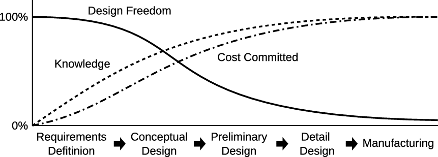
Aircraft design stages, based on Mavris [Reference Mavris and DeLaurentis23].

1.1 Modular aircraft model definition for an aerostructural performance optimisation
At any stage of an aircraft design process, an aerostructural optimisation model can be split into two major parts. The structural and performance criteria models. In an industrial setting, this distinction is a common one, mainly driven by the methodologies and requirements of the various departments contributing to the overall design at different development stages. In an early conceptual design, empirical equations are often used to represent various physical effects including aerodynamics, structural weight estimation and performance evaluation. Although the analytical methods are likely limited, their simplicity allows for an evaluation of a large number of configuration proposals in a short time. As the development progresses, further simulation models are created to support evaluation of effects previous analyses have possibly neglected. These new models do not only come with a higher computational cost, but with an increased modeling cost as well. It can be argued, that any available solver can find a practical application in an industrial setting, as long as the assumptions a solver makes are in line with the scope of the design stage it should be deployed in. The same is valid for all physical models involved in an aircraft configuration optimisation process. Mavris [Reference Mavris and DeLaurentis23] has presented a qualitative diagram showing the progression of a design freedom and cost commitment during an aircraft development. The Fig. 1 postulates that as an design maturity increases, a need for more precise simulation methods escalates. This interaction is a major motivator for employing more accurate models even in earlier stages of a design process, partially to mitigate the risks of having to rework a proposed design that is deemed as unfeasible when tested using methods of a higher accuracy. In an ideal scenario, an optimisation framework should be able to support tools and models across all design stages, allowing the various phases to bleed into one another.
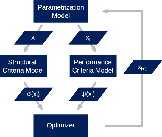
The complexity of a physical model and its interactions is close to infinite in the scope of an MDO due to the large number of disciplines that can be involved. Even though the details and physical representations of an investigated configuration change as time progresses, some questions in regards to the design remain unchanged. Any optimisation process will be looking for the best possible design that can satisfy a set of requirements while exposed to a specific set of constraints by improving a suitable performance measure. Hence, it is of a benefit to define a physical representation of an aircraft, which is used to obtain necessary simulation data, as an enclosed entity from the point of an optimisation process. This study utilises two different aircraft models of the same configuration. One for the purposes of ensuring a design feasibility which is used to evaluate structural criteria
 $\sigma $
while the other is used to simulate an aircraft performance
 $\psi $
. As the Fig. 2 shows, even though these models have no direct interaction in between them, they propagate changes in a parametrisation model in the form of an mutually consistent update of design variables
 ${x_i}$
in each optimisation iteration i.
Structural and performance criteria model responsibilities.

In the scope of an aerostructural optimisation, the structural criteria model is responsible for the assurance of a design feasibility. The first step in establishing a valid criteria model is the selection of load cases, which should be simulated. For a large civilian aircraft the definition of flight states that have to be investigated is for example governed by the Certification Specifications and Acceptable Means of Compliance for Large Aeroplanes [24]. It is possible, especially in the early design stages, that information about the aircraft is quite limited and doesn’t allow the definition of all the required flight states. Hence, a subset of criteria is often selected based on the aircraft features being investigated at the moment. In this study the structural criteria are applied in the form of optimisation constraints on the FEM model. These include represented by stress constraints and local buckling constraints. Ideally, many further constraint types should be included as the design progresses and gains on detail. These could include fatigue, joints, manufacturing constraints and others. Hence, it is of possible benefit to select a structural FEM solver, that can include or exclude various criteria, supports optimisation and can obtain loads from a variety of CFD solvers.
The performance criteria model is used to evaluate the overall aircraft indicators like weight, range or endurance. Additionally, the same model can require an introduction of extra constraints like maximum altitude or MTOW. A common indicator used in many aircraft related optimisation tasks is the structural weight of an aircraft. This value can be obtained by empirical equations based on historical data, for example those mentioned by Raymer [Reference Raymer22]. If a FEM model of an aircraft configuration is available, the weight can be obtained directly from such a model. When an actual realistic in-flight behaviour should be estimated, the inclusion of a structural response in dependence on a aerodynamic loading becomes necessary.
1.2 Performance optimisation of an passenger aircraft
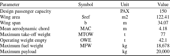
The concept of a targeted application of different aircraft models in a single optimisation procedure has been applied in a task of a performance optimisation of a passenger configuration close to that of an Airbus A320. Global parameters of the configuration are presented in the Table 1. The optimisation concentrates on a situation common in the early steps of a preliminary design stage. The outer shape is already frozen, engine selected and requirements set. Only the structural elements of the wing are a subject to the optimisation. A similar task can occur if it is decided, that a wing should be internally redesigned on an already manufactured configuration to reduce the weight but keep the existing tooling. Or the outer shape has been set in earlier stages of the design process and is not allowed to be changed anymore.
Overall aircraft parameters from [Reference Risse, Schäfer, Schültke and Stumpf25]

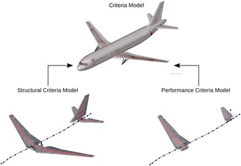
The concrete model used as the base is the Common Research Model [Reference Risse, Schäfer, Schültke and Stumpf25]. To effectively support a structural criteria model and a flight performance criteria model, two FEM models were derived from the same source. The separation and simplification shown in the Fig. 3 was done with the intention to keep computational times in check while assuring an equivalent structural response and parametrisation propagation across the models. The whole wing was kept in the structural criteria model, since the list of load cases intended test the stability of the structure commonly include a non-symmetrical manoeuvre conditions. On the other hand, the flight states used for a performance evaluation are almost always symmetrical, as these are the states an aircraft spends the most time in. Hence, only half model has been used in the performance simulation while the VTP has been removed, replaced only by a concentrated mass attached to the rest of the FEM model. The FEM model consisted of a combination zero dimensional concentrated mass elements, one dimensional rod elements, beam elements based on a Timoshenko theory and two dimensional shells introduced by Bischoff [Reference Bischoff26], with the discretisation level shown in the Table 2.
FEM simplification for a structural and a performance criteria model.

Number of element types on each component of the structural criteria FEM model

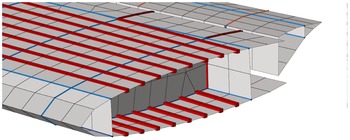
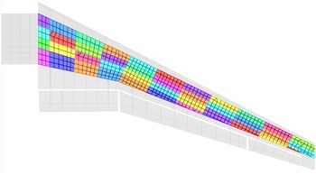
The wing, the horizontal vertical tailplane (HTP) and the vertical tailplane (VTP) have been modeled in an analogous manner, utilising one dimensional beam elements for longitudinal stringers and rod elements for spar and rib caps. Skins, spars and ribs were created using two dimensional shell elements. The centre wingbox was modeled from aluminium, whereas the leading and trailing edges were fashioned from a honeycomb sandwich structural elements. An example of the used wing FEM model is provided by a wing section provided in the Fig. 4.
Detail of the wing FEM mesh.

In both cases, the fuselage has been strongly simplified by replacing the detailed structural model with a one dimensional representation. An appropriate structural behaviour of the fuselage was assured by using an equivalent beam model approximating the bending and torsional stiffness of a fully modeled fuselage. The stiffness parameters of the beam elements were estimated by a numerical simulation through application of unit forces and moments on fuselage sections which coincided with the beam endpoints. The weight approximation was handled by adding a zero dimensional condensed mass elements at the end points of the fuselage’s beam elements. These were to model structural and system weight together with additional mass elements to represent a payload mass, which could be modified depending on a required mass configuration.
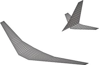
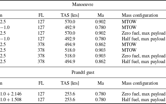
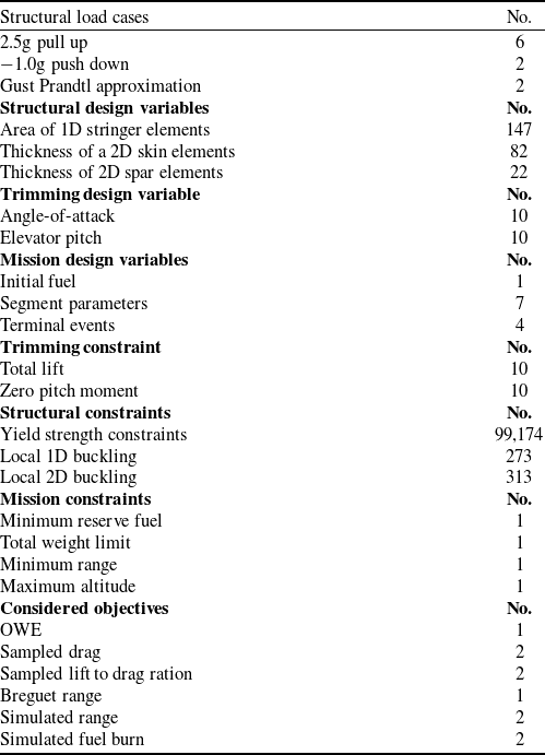
Each of the two aircraft models has utilised different source of aerodynamic forces. For the structural criteria model, a panel-based VLM solver called Athena Vortex Lattice (AVL) was used. As this model was meant to evaluate the effect of aerodynamic loading on structural elements of the wing, the main contribution to wing deformation was coming from forces related to lift. Hence, a precise modeling of drag was likely less important when evaluating structural criteria. The model consisted of 1,288 panels distributed among wing, HTP and VTP as shown in the Fig. 5. The AVL solver was coupled to a FEM solver using an Infinite Plate Spline mapping [Reference Harder and Desmarais27] and utilised the Fixed Point Iteration method [Reference Hoffman28] to obtain a converged solution of the multi-field equation system. The structural criteria model included strength constraints, making sure the stress across all simulated load cases shown in the Table 3 remained below the yield limit of the used material, including an industrial safety factor. Additionally to strength constraints, the Table 4 summarises other structural constraints applied in the optimisation model, including one- and two-dimensional local loss of stability constraints applied along the wingbox.
AVL model.

Structural load cases

Summary of optimisation model

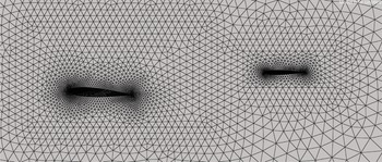
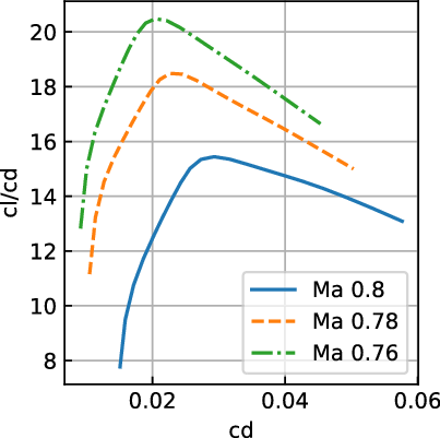
In comparison to the structural criteria model, the performance criteria model required a more reliable estimation of drag. In an attempt to obtain a reasonable balance between computational time and an accuracy, an aerostructural analysis using an aerodynamic database has been selected. For this, a CFD model of a half of the aircraft with applied symmetry plane has been created, shown in the Fig. 6. Consequently, a large number of sample points have been simulated using an Euler fluid solver from the SU2 suite [Reference Economon, Palacios, Copeland, Lukaczyk and Alonso29] using a model with 108,459 tria elements describing the surface of the wing and HTP. The sample points have been varied by a Mach number, angle-of-attack and a stabiliser deflection, for which the whole HTP has been rotated in the mesh itself, resulting in a trimmed polar shown in the Fig. 7.
Look at the symmetry plane of the SU2 model.

Trimmed SU2 polars for a selection of Mach numbers.

Consequently, the database was created from these sample points by integrating pressures on various surface sections of the wing and the HTP. The resulting forces were then mapped onto the wing at specific sections and distributed to the surrounding elements by using load distributing elements. Once again, a converged solution of the coupled system was obtained by a Fixed Point Iteration method. Since an Euler solution doesn’t provide an estimation of the friction drag component, this contribution to the overall drag was additionally evaluated using an empirical formulation and was added as a scalar value, resulting in the polars shown in the Fig. 7. As such, the viscous drag didn’t have any influence on the deformation of the wing during an aerostructural simulation, although its impact on an overall wing bending is likely negligible.
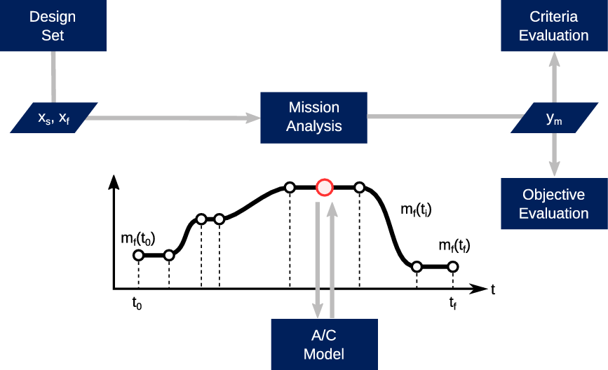
The above described aircraft representation was used for a simple- and multi-point performance evaluation and inside of a coupled mission simulation, as shown in the Fig. 8. For those objective functions, which required an inclusion of a fully coupled mission analysis, additional constraints and design variables were integrated into the optimisation problem. These related to the mission profile definition and variability, resulting in additional constraints and design variables as summarised by the Table 4. During the climb phase, thrust settings of the engines were defined as segment wise constant design variables during climb steps, together with the rate of climb. Terminal events like the altitude at the end of the climb, the fuel ratio at which a climb step should be started and the length of the second cruise leg were designated as design variables as well.
Contribution of a mission analysis as a performance criteria model.

To allow for a consistent definition of structural design variables, the wing FEM model has been kept identical for both the structural criteria and the performance criteria model. The number of design variables and their types has been kept relatively small to allow for a quick computation and to show that a significant change in structural design and overall performance is possible even with a limited design freedom. The overall breakdown of the used design variables is shown in the Table 4. These variables were concentrated patch-wise over the wingbox of the right wing, visualised in the Fig. 9, and were linked to the structural elements of the right and left wing in a symmetrical manner. The ribs were left out of the optimisation, since the fidelity of the FEM model used in this study didn’t support a realistic rib sizing due to the lack of holes and cutouts as well as neglecting potentially relevant load cases.
Design variables patches on the right wing’s upper skin.

A quasi-stationary trimming analysis was included in the simulation model to guarantee that a performance and structural behaviour was evaluated at viable flight conditions. The requirement was to balance all forces acting upon the structural model, including thrust
 ${p_T}$
, weight
 ${p_g}(\delta )$
, inertia due to acceleration
 ${p_e}(\delta )$
and aerodynamic forces
 ${p_a}(w)$
influence by displacements u. The way a trimmed flight state was enforced in the structural criteria model and the performance criteria model differed. In the FSI analysis of the structural criteria model, a trimmed state was enforced only at the converged state of an optimisation procedure. This was achieved by adding two additional constraints for each load case in the form of a sum of forces in the lift direction and sum of moments around the pitch axis. At the same time the angle-of-attack and elevator pitch were selected as trimming variables and added to the overall optimisation model. Hence, during the optimisation process, a trimmed state was not necessarily assured at each iteration step. This avoided the need to integrate an additional internal loop in the FSI solver and hence allowed a faster evaluation of the overall problem by avoiding the outer loop B from the Fig. 10.
Trimming loop inside of a performance criteria model.

To allow a sequential evaluation of flight states in each optimisation iteration, required by the coupled mission analysis, an extension of the FSI system was necessary. An outer loop analysis B was added, which expressed a force balance as a residuum and used the sensitivity analysis of the trimming constraints w.r.t. design variables, already developed for the structural criteria model, as a Jacobian to be used in a Newton-Raphson solution. The introduced scheme followed the Fig. 10.
 \begin{align}{p_{tot}}(\delta ,u,w) = \sum {p_a}(\delta ,u,w) + \sum {p_e}(\delta ) + \sum {p_g}(\delta ) + \sum {p_T}(\delta )\end{align}
Whereas the selection of constraints for the structural criteria model is often clearly defined by physical limitation of materials and a structural layout, the selection of an objective function is not as unambiguous. To present a case for the importance of a selection of an optimisation target, a number of objective functions were evaluated and compared. These included a structural weight, point-wise computed drag or lift to drag ratio, range estimated using the Breguet equation and finally range and trip fuel values obtained by performing a fully coupled mission simulation. The standard structural weight objective value is obtained by summing up the individual element mass
 ${m_{FEM}}$
of all the N elements in the used FEM model, as defined by the Equation (2).
 \begin{align}\psi (x) = {\sum^N {{m_{FEM}}(x)} } \end{align}
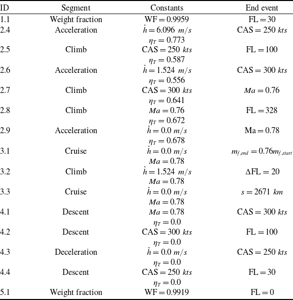
The objectives using drag D and a lift to drag ratio L/D were evaluated based on data obtained from a simulated the reference mission, given by the Table 5, with the initial non-optimised structural model. The sampled flight states were selected by a uniform discretisation of the cruise segments of the mission profile. A trimmed aerostructural response and sensitivity analysis was performed for each of the n selected sample points using the fuel value obtained by the initial mission analysis to obtain a realistic flight state. The drag and the load to drag ratio values were weighted by a time range
 $\Delta t$
for which the sample point lied in the middle, as presented in the Fig. 11. Example for the drag objective is described by the Equation (3).
 \begin{align}\psi (x) = \sum\limits_{i = 1}^n D\left( {{m_i},{\delta _i},x} \right)\Delta {t_i}\end{align}
Uniform sampling of points on a simulated mission profile.

The Breguet equation [Reference Raymer22] approximates a maximum range given a representative flight performance and total aircraft mass at the beginning and the end of a cruise segment. The equation Equation (4) shows the formulation used in the optimisation, in which the initial and end mass,
 ${m_1}$
and
 ${m_2}$
respectively, were obtained using weight fractions [Reference Raymer22]. To obtain the mass at the start of a cruise segment
 ${m_1}$
, a mass at take-off was multiplied by a weight fraction for take-off and climb. On the other end the mass at the end of a cruise segment
 ${m_2}$
was obtained by dividing a mass at landing, assuming only reserve fuel present in the fuel tanks, by a weight fraction for descent and landing. The concrete weight fraction (WF) values were obtained using results from a simulation of the reference mission and are presented in the Table 5. The lift to drag ratio L/D, the true air speed
 ${v_{TAS}}$
and the thrust specific fuel consumption
 ${c_{TSFC}}$
used in the Breguet equation were averaged from the values obtained at the sample points.
 \begin{align}\psi (x) = - {{{v_{TAS}}} \over {g{\kern 1pt} {c_{TSFC}}}}{L \over D}\ln \left( {{{{m_1}} \over {{m_2}}}} \right)\end{align}
Initially, the mission trip fuel objective has been evaluated using a fully coupled mission analysis given a fixed flight path settings. The flight profile was created as a sequence of segments, listed in the Table 5. Each of the segments was defined by a pair of constant flight parameters, including a rate of climb
 $\dot h$
, thrust setting
 ${\eta _T}$
, calibrated air speed (CAS) or a Mach number Ma. Flight state parameters like a flight level (FL), CAS, Ma or a fuel ratio
 ${m_{f,end}}/{m_{f,start}}$
were used as terminal conditions across the various segments. On the other hand the mission range objective has included an additional design variable in the form of the length of the second cruise segment. Later, a simultaneous mission trip fuel and profile optimisation has been performed as well, with the target of evaluating any potential benefits of such a coupled process by comparing the optimisation results with those obtained by considering a fixed profile approach.
Initial reference mission used during optimisation

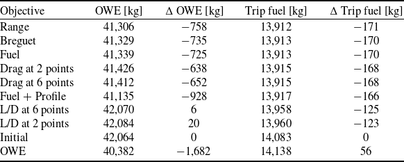
After each of the optimisation runs has converged, a series of secondary mission simulations and structural analyses were performed using the obtained designs. Assuming a prescribed path, the optimisation results are summarised in the Table 6. Based on the obtained fuel consumption values, the often used structural weight as a performance indicator subject to optimisation was likely the worst choice out of all the considered ones. The OWE design achieved the lowest structural weight and at the same time it provided the lowest torsional stiffness of the wing, as the Fig. 12 shows. The high flexibility of the wing seemingly lead to an in-flight shape that strongly deteriorated the performance and as such has lead to an increase in fuel consumption compared to the initially proposed design. Another objective which has shown itself in all likelihood to be an unsuitable choice was the lift to drag ratio. The obtained design provided the highest stiffness at the expense of an increase in structural weight. The lack of any reduction in the OWE was probably caused by the lift being directly coupled to a total mass of the aircraft. Through trimming the lift had to offset the mass, hence increase in mass has lead to a gain in lift and therefore the lift to drag ratio has risen as well. The only limiting factor was that an increase in lift purely through mass has stopped yielding any benefits when the rise of an angle-of-attack had lead to an excessive drag. All other objectives have lead to a very similar numerical results. The Breguet equation provided a reliable performance indicator for the reference mission. A single- and multi-point drag objective function managed to achieve a significant design improvement as well. The close match between sampled performance indicators and those evaluated using an actual mission analysis can be most likely linked to an accurate selection of sample points, which had been evaluated based on an initial mission simulation with a fixed flight profile.
Optimisation results for a fixed profile

Wing deformation under 2.5g across optimisation results.

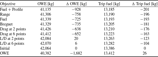
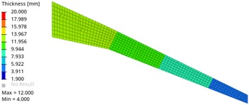
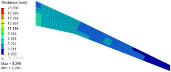
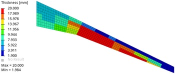
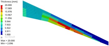
Consequently an optimisation allowing for a modification in a flight path was performed, whose results are summarised in the Table 7. An additional mission profile optimisation has yielded further reduction in fuel consumption for each of the designs. Figs 15, 16, 17 and 18 show an optimisation thickness distribution of the upper wingbox skin for an initial, minimum structural weight, minimised lift to drag ratio and minimised fuel burn design, respectively.
Optimisation results for an optimised profile

Optimal mission profiles after optimisation.

Change of payload-range capability due to optimisation.

Upper skin thickness distribution of initial design.

Upper skin thickness distribution of optimised for OWE.

Upper skin thickness distribution of optimised for L/D.

Upper skin thickness distribution of optimised for fuel plus profile.

Optimal flight profiles of the reference mission were evaluated for each of the obtained designs. The target of the mission path optimisation was the overall trip fuel. The results shown in the Fig. 13 are limited to only a small selection from all the considered objectives, since many of them result in a similar design and a close flight path. The only major outlier was the path flown by the design obtained by minimising the structural weight. On this path, the amount of fuel burnt during the first cruise segment has increased compared to the initial path at an higher altitude, while the amount of fuel used up during the second cruise segment of the updated profile has decreased significantly. It is likely that the higher amount of fuel had consumed at the beginning allowed the aircraft to decrease the amount of lift needed and hence has reduced the loading on the wing, mitigating the increased torsional flexibility of the optimised OWE design.
To investigate the overall change to the aircraft performance, a payload-range envelope has been drawn in the Fig. 14. The corner points of the diagram were obtained by maximising the range for various payload levels. Point B represents a maximum achievable range with a maximum payload of 20t on board. Point D was computed assuming no payload. Point C marks the maximum range at a MTOW limit. The Fig. 14 shows that even though the main optimisation was done only for one reference mission, which was at the edge between the points B and C, the overall range was increased. This is even the case for the design obtained by minimising the structural weight, which has shown results indicating an actual loss of performance for the reference mission. The range was mainly dictated by the amount of fuel that can be taken on board, especially at the MTOW limit of the payload-range envelope.
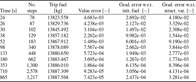
A trade-off between a mission analysis accuracy and computation time has been investigated by running a mission sensitivity analysis of the reference flight profile with varying levels of discretisation using the Forward Euler Iteration scheme. The numerical error has been evaluated w.r.t. a benchmark solution obtained by using a Runge-Kutta method of order 4 [Reference Dormand and Prince30] with a discretisation of 554 steps. The simulation was performed on a single machine with a processor consisting of 16 single-threaded cores, resulting in the computational times shown in the Table 8. Based on the observed results, a rough discretisation has been used throughout optimisation for exploration while a larger number of steps has been used during the final exploitation.
Time vs. accuracy trade-off

2.0 Conclusion
A use of two modular aerostructural models inside of a single optimisation problem with the intention of exploiting the trade-offs between a simulation complexity and accuracy has been investigated. This has been achieved by considering two different FEM representations with distinct sources of aerodynamic data. One of these aircraft models has been dedicated to a structural criteria model intended for the evaluation of structural feasibility and stability constraints, while the other model was used only for the evaluation of flight performance.
The use of a simpler but faster aerodynamic solver for the purposes of loads generation to evaluate stresses and strains at critical loads should allow to investigate a larger number of quasi-stationary load cases at flight states far away from a 1g cruise. At the same time, the use of aerodynamic forces stemming from higher fidelity sources inside of a performance criteria model offers a more reliable estimation of a behaviour at a much more limited range of flight states during cruise. The same aerostructural performance criteria model has been reused in various optimisation problems, each targeting separate commonly used performance measures, including a fully coupled mission analysis. To assure that the aircraft model behaviour is properly integrated into the mission analysis, the use of surrogate models has been avoided and instead the aircraft’s behaviour has been simulated at every discretisation point of the mission profile, together with a sensitivity analysis.
The second phase of this study has shown the importance of selecting an appropriate objective function for an economical structural aircraft design. It has been shown, that for a mid-range mission, the classical Breguet equation used as an objective function converges to a wing’s structural stiffness distribution very similar to that coming form an optimisation performed with a fully coupled mission analysis. Although, this can be assured only if the sample points used to evaluate the various components of the Breguet equation are based on an accurate estimate of the final mission path. By optimising the flight path for each of the designs, using the performance criteria model only, it has been found out, that the final optimal mission profile for each of the design lies very close to the initial one, confirming the viability of the selected sample points. The commonly used minimisation of structural weight as an optimisation target has shown itself to be detrimental to an overall fuel consumption of an aircraft. Even though this study has shown that an appropriate flight routing can offset the losses in flight performance, the fuel consumption still stays above the designs obtained by using other objective functions. Finally, the results generated in this study indicate, that a flight routing should be considered during any aerostructural optimisation, as it has a major impact on the overall flight economy of an aircraft and is necessary to present realistic trade-offs.
The established procedure and presented results should motivate the use of a more modular approach to a model preparation and even the use of differing aerostructural models targeting their specific purposes. The used procedure and mission analysis allows to integrate future optimisation problems targeting a larger selection of design variables, including shape modifications. At the same time the established integration of a fully coupled mission analysis provides the possibility to properly include a larger set of statistically weighted realistic missions in a single optimisation procedure, leading to more economical flight across a whole lifespan of a newly designed aircraft.
Acknowledgements
The authors would like to thank the Airbus Defense & Space, Germany for their support.