Introduction
Discharge of a capacitive storage to a load via a unipolar pulse is employed in the pumping of powerful lasers (Miller et al., Reference Miller, Moses and Wuest2004; Cavailler, Reference Cavailler2005), feeding of electromagnetic launchers (Hsu et al., Reference Hsu, Merritt, Moser, Awe, Brockington, Davis, Adams, Case, Cassibry, Dunn, Gilmore, Lynn, Messer and Witherspoon2012), and pulsed high magnetic field facilities (Zherlitsyn et al., Reference Zherlitsyn, Wustmann, Herrmannsdörfer and Wosnitza2012). Spark gaps are associated with an impressive range of voltages, currents, charge transfers and repetition rates, and an extremely wide range of applications. The main drawback of spark gaps is their limited lifetime, which is related either directly or indirectly to the erosion of the electrodes. Various types of switches have been introduced that utilize the principle of arc motion in a magnetic field, thus effectively decreasing the current density at the switch electrodes (Rim and Cho, Reference Rim and Cho2000; Jaitly et al., Reference Jaitly, White, Cassany, Eyl, de Cervens and Mexmain2005).
Three-electrode rail-type switches with the electrodynamic acceleration of the spark channel (similar to coaxial plasma jet accelerators) were developed, investigated, and thoroughly tested by Kovalchuk et al. (Reference Kovalchuk, Kim, Kharlov, Kumpyak, Tsoy, Vizir and Zorin2008b) for the LMJ facility (Kovalchuk et al., Reference Kovalchuk, Kim, Kharlov, Kumpyak, Tsoy, Visir, Smorudov, Kiselev, Chupin, Bayol, Frescaline, Cubaynes, Drouilly, Eyl, Cassany, Courtois, Patelli, Mexmain and De Cervens2008a). Later, a two-electrode spark gap with inductive coupling in a triggering circuit (Kovalchuk et al., Reference Kovalchuk, Kharlov, Kumpyak and Tsoy2015) was introduced with significant extensions of the operational range and charging voltage. In some applications, a unipolar pulse is not feasible, and an oscillatory (underdamped sinusoidal) regime must be realized for the capacitor bank discharge. In particular, this is valid for pulse magnetic technology, where a constant frequency is required throughout the pulse, and this approach is used for assembling, welding, cutting, and forming products in various branches of industry (Kore et al., Reference Kore, Date and Kulkarni2007; Cui et al., Reference Cui, Lib, Mob, Fang, Zhou, Xiao and Feng2016; Mishra et al., Reference Mishra, Sharma, Kumar, Sagara, Meena and Shyama2017).
Several machines have been developed for each of the aforementioned categories, and these are characterized mainly by energy storage on the order of ten to a hundred kJ, working voltages of 6–40 kV, and a full pulse length of 100 µs to several ms. Electromagnetic forming is a high-speed forming technology that uses a pulsed magnetic field to apply Lorentz's forces to workpieces, without mechanical contact and without a working medium. In this way, hollow profiles can be compressed or expanded, flat or three-dimensionally (3D) preformed sheet metal can be shaped and joined, and cutting operations can be performed. Due to the extremely high velocities and strain rates involved, in comparison with conventional quasi-static processes, the forming limits can be extended for many materials. Additional advantages include the environmental friendliness of the process, the high repeatability that can be achieved for the proper design of a pulse generator, and the easy adjustment of the applied forces via the charging energy and the voltage. The review in Psyk et al. (Reference Psyk, Risch, Kinsey, Tekkaya and Kleiner2011) summarizes publications and advances in the field of electromagnetic forming and covers the following aspects: Principles of electromagnetic forming, process analysis, material behavior at high strain rates, equipment used in electromagnetic metal forming, applications, and future research directions. Spark gaps with electrodynamic acceleration of the spark channel, developed for unipolar discharge, cannot directly be employed in an under-damped (oscillatory) regime, since at the current transition through zero the arc channel could stop motion and ignite at initial place on the following half period (the characteristic timescale for this is from hundreds of μs to ms). The process of arc ignition and motion becomes more complicated in the oscillatory regime of capacitor bank discharge. This phenomenon was observed by investigating the moving spark behavior (Cho et al., Reference Cho, Rim, Lee, Kim and Jin2001) in the coaxial rotary switch. The conclusion drawn in Cho et al. (Reference Cho, Rim, Lee, Kim and Jin2001) is that the re-ignition points are dependent on the magnitudes of the current; it is shown that for the lowest current, the point of re-ignition is close to the point of the first ignition, but as the spark current increases, re-ignition after zero-crossing of the current is initiated at the same point at which the spark was extinguished.
A prototype of a compact gas switch, intended for operation in the oscillatory (low damping) regime of discharge, was introduced in Kharlov et al. (Reference Kharlov, Kovalchuk, Kumpyak and Tsoy2017). This is a two-electrode switch with the electrodynamic acceleration of the spark channel and an inductively decoupled trigger generator. Two operational regimes were investigated in this study: A “fast” regime with current amplitude ~160 kА, total charge ~12 C, period of oscillation 60 µs, and full pulse length ~400 µs; and a “slow” regime with current amplitude ~30 kА, total charge 18 C, period of oscillation 360 µs, and full pulse length ~3 ms. The spark gap is designed for a charging voltage of 50 kV at a current of up to 200 kA, and a charge transfer of up to 20 C.
Until now, in the simulation of electromagnetic launchers, the plasma motion and electrode heating have been considered separately (Borkowski and Hasegawa, Reference Borkowski and Hasegawa2007; Zhukov et al., Reference Zhukov, Reznikov, Kurakin and Rozov2007). A joint treatment is required, since the thermal process at the electrodes influences the formation and motion of the plasma jet (e.g., by merging part of the ablated electrode material into the plasma jet). The objective of this paper is the numerical simulation of an arc movement in the rail gap geometry that is self-consistent with the thermal process at the electrodes, as this is important in a consideration of the energy deposition at the electrodes and hence their erosion and degradation. Two main issues are examined in this work: (i) The development and testing of a simulation model of spark channel motion in linear rail geometry, which is valid both for the oscillatory (hitherto unaddressed) and unipolar regimes of capacitor bank discharge; (ii) an investigation of arc motion and electrode heating depending on the current and charge transfer over a wide range of operation.
Main features of bipolar regime
Criteria for the choice of geometry
Electric field strength
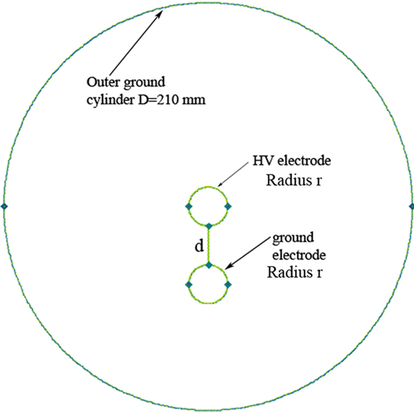
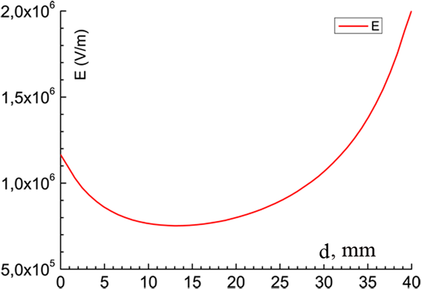
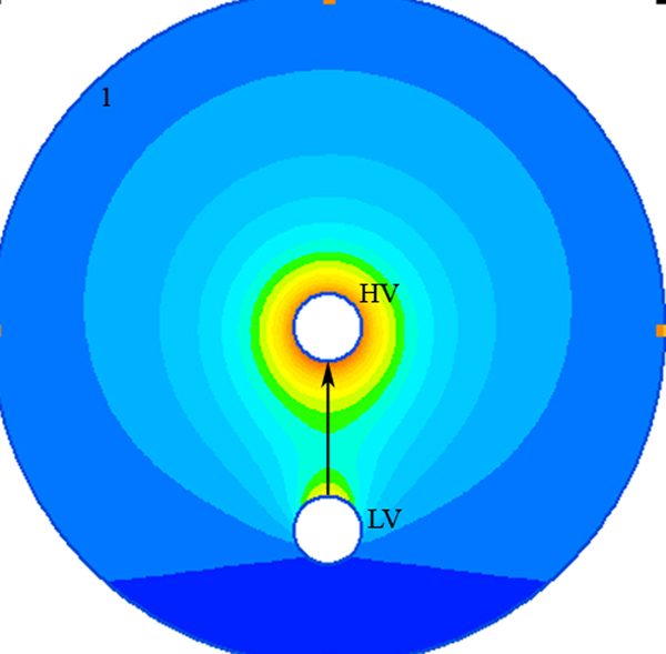
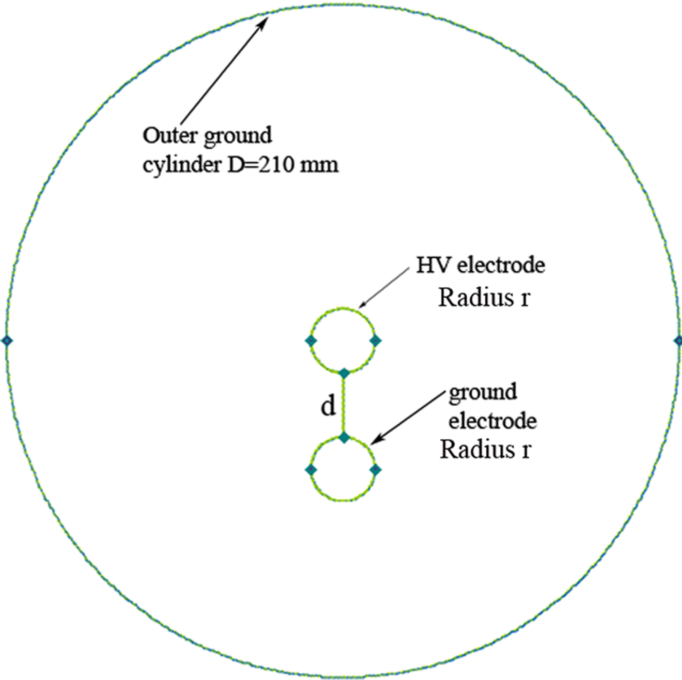
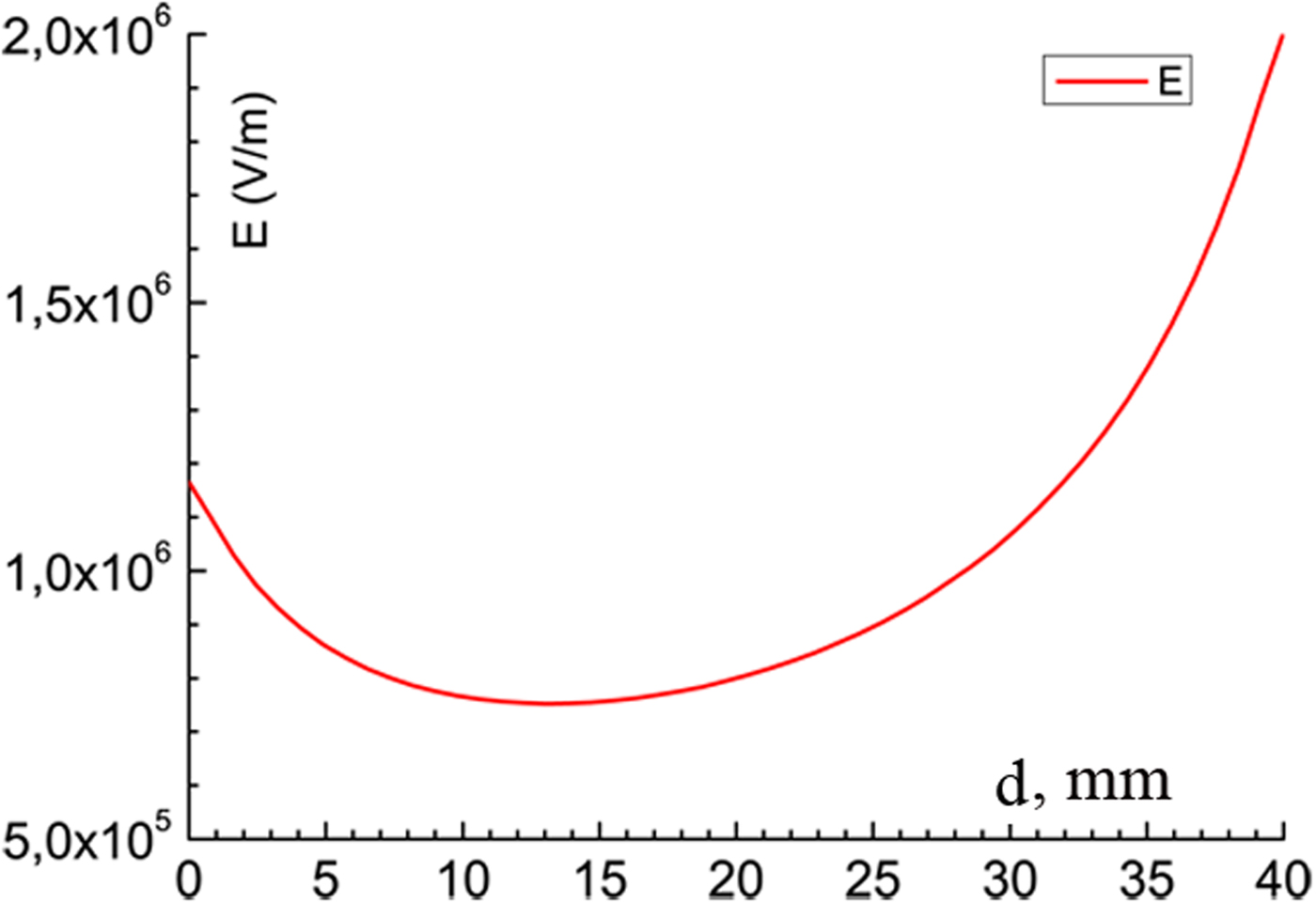
The switch design used as the prototype for these simulations is described in detail elsewhere (Kharlov et al., Reference Kharlov, Kovalchuk, Kumpyak and Tsoy2017). The main feature of this switch is that it comprises two parallel cylindrical electrodes embedded in a single body. A general sketch of the electrode geometry is given in Figure 1. There are conflicting requirements for a comparison of the spark motion under the influence of a magnetic field and the required electric field strength. Figure 2 shows the electric field between electrodes at 40 kV, r = 10 mm, and d = 40 mm, and Figure 3 presents a 2D map of the electric field. It can easily be seen that the electric field is very nonuniform, with a maximum at the high voltage (HV) electrode and a minimum in between (with an approximately threefold difference). The high magnetic field requires small electrode radii, and this results in strong nonuniformity of the electric field. The grounded body of the switch also has a significant impact on the electric field distribution between the electrodes, pushing the electric field back from the low voltage (LV) electrode.
General sketch of the electrodes geometry.
Electric field on line between LV and HV electrodes at 40 kV, r = 10 mm, d = 40 mm (d = 0 and d = 40 mm correspond to the LV and HV electrodes, respectively).
Electrical field map at 40 kV, r = 10 mm, d = 40 mm. Arrow line corresponds to Figure 2. graph.

Arc motion
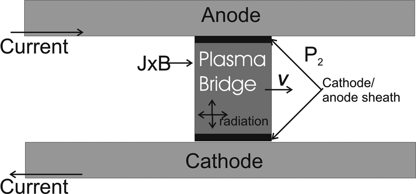
The motion of the spark channel along the switch electrodes naturally decreases erosion of the electrodes, which in turn decreases the sputtering of the insulators and their decontamination by erosion products. This decrease in the erosion also leads to a constant form of the electrodes, and creates a stable breakdown voltage and time delay of the switch operation. The effect of arc velocity on cold electrode erosion was studied in Essiptchouk et al. (Reference Essiptchouk, Sharakhovsky and Marotta2004) for relatively low currents and velocities. The velocity of a plasma channel is defined by equilibrium between the magnetic force and the air drag force acting on a plasma channel (Kharlov, Reference Kharlov2010). The plasma channel is accelerated along the electrodes due to the force j × B exerted by the discharge current I(t) (Fig. 4). This model is also valid for parallel-plate electromagnetic plasma accelerators operating in gas-filled mode (Hsu et al., Reference Hsu, Merritt, Moser, Awe, Brockington, Davis, Adams, Case, Cassibry, Dunn, Gilmore, Lynn, Messer and Witherspoon2012; Liu et al., Reference Liu, Huang, Guo, Lin, Huang and Yang2018). Similar behavior is observed in vacuum interrupters, which apply a transverse magnetic field for spark control (Feng et al., Reference Feng, Xiu, Wang, Liu, Zhang and Bi2015).
Sketch of arc motion.

The arc motion in the atmospheric pressure air produces a shock wave that exerts a retarding pressure P 2 on the accelerating plasma channel. The magnetic force can be written as the product of the current, the average magnetic field through the channel length, and the channel length F m(t) = I(t) × B m(t) × d. The air drag force acting on a plasma channel  $F_{P_2}(t) = P_2(t) \times S$, where S = b × d is the channel area normal to the motion and P 2(t) is the pressure between shock wave and plasma piston. A retarding pressure is created on the plasma channel of
 $$P_2(t) = \displaystyle{{{{\rm \gamma}} + 1} \over 2} \times {{\rm \rho}} _1 \times v^2$$
where v is the plasma channel velocity, γ is the adiabatic index and ρ1 is the air density under ambient conditions.
In order to increase the average magnetic field throughout the channel length, it is desirable to decrease both the diameter of the electrodes and the channel length. However, both of these actions tend to increase the maximum electric field in the inter-electrode gap and limit the maximum operational voltage. Although it is possible to raise the operational voltage via an increase in pressure, the air drag force would rise in the same way, reducing the spark velocity and increasing erosion. Preliminary experiments were carried out with a range of electrode diameters of 12, 16, 20, 30, and 40 mm and a varying gap between 30 and 40 mm. Based on these experiments, 20 mm diameter electrodes were identified as optimal for the developed switch.
Experimental layout
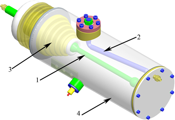
The switch assembly is shown in Figure 5. The HV electrode is fixed in the insulator (3), and the LV electrode is fastened to the switch body by a flange; both electrodes are made from copper. The position of the LV electrode (2) can be adjusted in the vertical direction. A specific feature of the switch design is that the LV electrode is tilted at ~20° in order to reduce the inter-electrode gap at the beginning of the electrode system and to fix the site of initiation of breakdown. The gap between the LV and HV electrodes can be varied between 20 and 40 mm.
Switch 3D assembly drawing:1 – HV electrode. 2 – LV electrode; 3 – transition insulator; 4 – switch body.

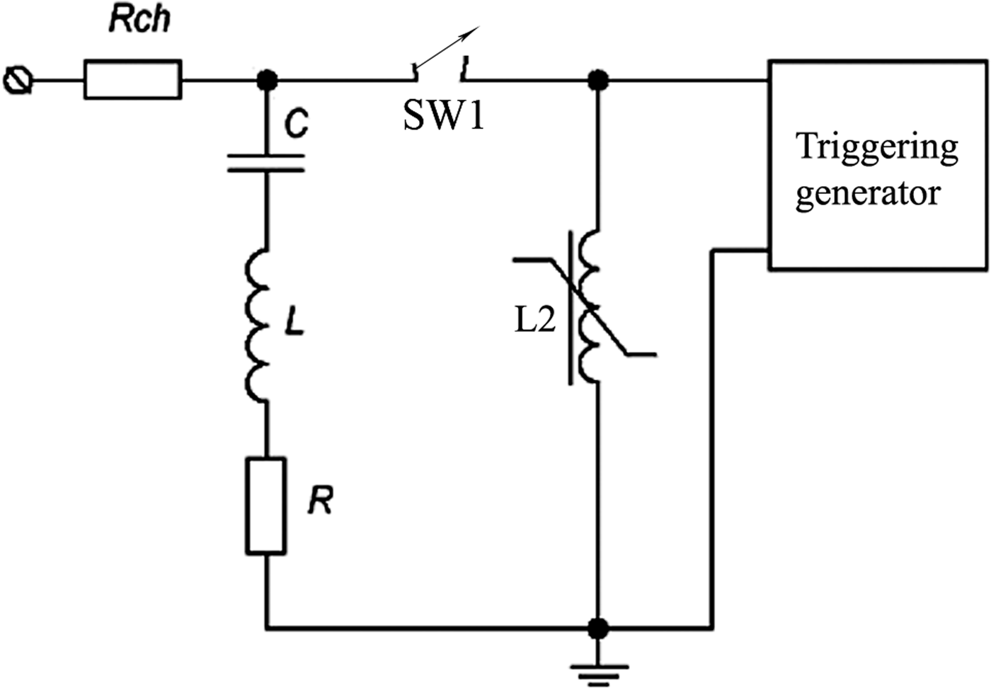
The principal electrical circuit for the testbed is shown in Figure 6. The capacitor bank С contains 14 IK50/3 capacitors (50 kV, 3 µF) connected in parallel, and the measured capacitance of the bank is 39.9 µF. The body of the main switch is connected to ground through a saturable inductor (4). An additional resistor R and inductance L define the required pulse shape and current amplitude. After the main spark gap breakdown, the inductor (4) cores are quickly saturated, and the switch body is connected with ground via a very low resistance. Bank C is discharged and the current pulse is formed.
Principal electrical circuit: Rch – charging resistor, L, R – pulse shaping elements, C – capacitive storage, SW1 – main switch, L2 – saturable inductor.

Investigated bipolar regimes
Fast and slow regimes
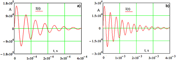
The switch was tested in two regimes called the “fast” and “slow” regimes. Transfer between these regimes requires a modest change in the discharge circuit. For the realization of the fast regime, an additional resistor R = 0.0125 Ω and inductance L = 0.54 µH are included in the discharge circuit. A simulated current waveform is shown in Figure 7a for this regime.
Simulated current waveforms for fast regime (a) and slow regime (b) at charging voltage of 40 kV.
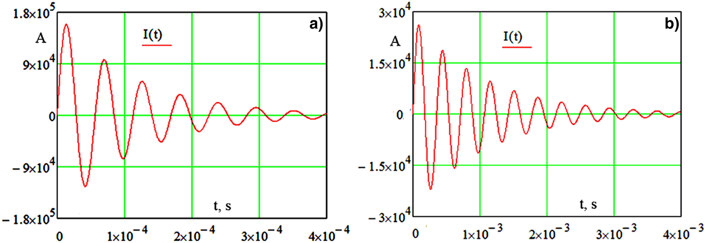
The current amplitude in Figure 7a is 160 kА, and the total charge (absolute value) is 13 C. The period of oscillations is 58 µs. To realize the slow regime, an additional resistor R = 0.1 Ω and inductance L = 82 µH are included in the discharge circuit. A simulated current waveform is shown in Figure 7b for this regime. The current amplitude for Figure 7b is 26 kА, and the total charge is 19 C. The period of oscillations is 360 µ. It is worth noting that the fast regime is typical for the magnetic forming of flat sheets, while slow is used for tubes.
Magnetic field simulation
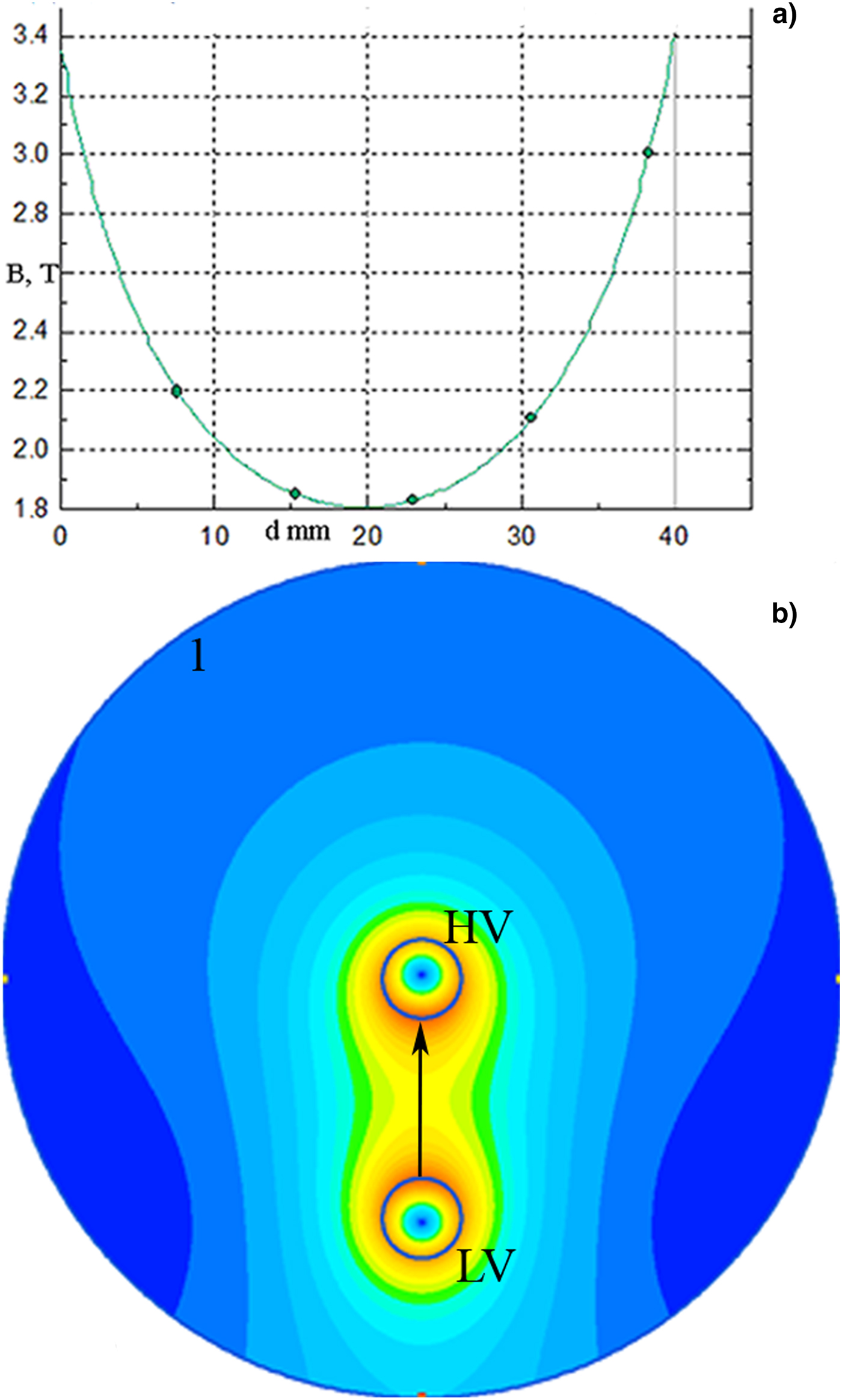
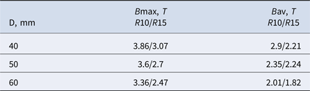
Figure 8 shows an example of a DC magnetic field simulation in a typical experimental geometry (radius of electrode 10 mm, distance between centers 50 mm, outer grounded cylinder of diameter 210 mm). Table 1 summarizes the results for the dependence of the magnetic field between the electrodes on the distance D between the centers of the electrodes. It can be seen from Table 1 that the electrode radius primarily defines the magnetic field values while the distance D between the centers of the electrodes affects this only slightly; an increase in the distance D slightly reduces the average magnetic field between the electrodes. It is also important to note that the external grounded cylinder (210 mm diameter) impacts on the magnetic field distribution to some extent and that this differs from the two wires field in free space. It can be seen from Table 1 that the electrode radii exert the predominant effect on the maximum magnetic field, which is obtained at the surfaces of the electrodes.
(a) Magnetic field on line between electrodes (HV–HV electrode, LV–LV electrode), (b) 2D map (Rel 10 mm, distance between centers 50 mm, outer grounded cylinder 1 of 210 mm diameter).

Dependence of magnetic field on distance D between centers of electrodes (Bmax is maximum magnetic field, Bav is average value, R10/R15 correspond to radii of 10 and 15 mm)

Arc motion in two regimes
Appropriate equations of motion can be written as:
 $$\displaystyle{{d(mv)} \over {dt}} = I(t) \times B(t) \times l-P_2 \times S$$
 $$\displaystyle{{d(m)} \over {dt}} = {{\rm \alpha}} \times I^2$$
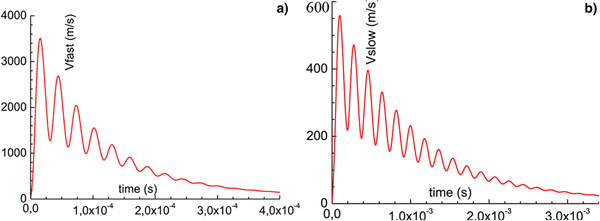
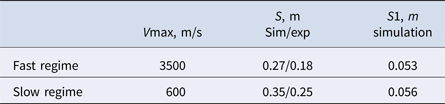
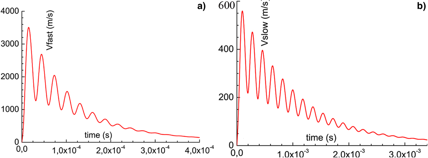
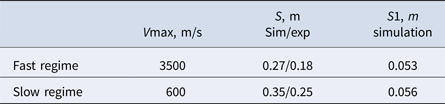
where I is the circuit current, B is the magnetic field in the spark area, l is the spark length (height of the rail channel), P 2 is the pressure in the area between the shock wave, moving ahead of the plasma in a stationary gas with velocity V1 and plasma volume, and S is the effective cross-sectional area of the plasma channel. Equations (2) and (3) are coupled with the electric circuit equation, which provides a waveform I(t) (Fig. 7). The ablation parameter α takes into account the mass involved in the motion with the accelerated plasma. Its value depends weakly on the current in the range 50–200 kA, and this can be approximated as α “4–6 × 10⁻¹² kg/(A2 × s)”. The initial conditions for Eq. (5) and (6) are clear: v (0) = 0, m (0) = m 0. Substituting Eq. (1) into Eqs. (2) and (3), we obtain a nonlinear differential equation that can be solved numerically for the spark velocity and the mass of the plasma channel. Figure 9 shows the calculated velocities of the spark channel for the fast (a) and slow (b) regimes. Table 2 shows the calculated results for the maximum spark velocity Vmax and the effective displacement S of the spark channel both for the fast and slow regimes. The obtained values of the displacement S are somewhat higher than the experimental ones (also shown in Table 2). This can be attributed to the fact that the velocity tail arising from the calculations contributes to the displacement S, though in fact the spark has already dissipated before this moment. This can be clearly seen from a comparison of Figures 7 and 9. The ratios of the displacement S for the slow and fast regimes correspond well in both experiment and simulation (approximately as the ratio of charged transfer, as follows from the developed theory). One important point is that the spark channel displacement in the first half period (column S1 in Table 2) should be close to (or more than) the inter-electrode gap in order to give continuous motion. This conclusion is drawn from experiments with electrodes of different diameters and from simulations. Local heating of the electrodes in the spark spot is not significant here (the temperature does not exceed 600 K, assuming regular motion without spark sticking).
Calculated velocities of the spark channel for fast regime (a) and slow regime (b).
Simulated maximum spark velocity Vmax and displacement S of the spark channel.
Unipolar regime
Arc motion
There are a number of works in the literature on the simulation of plasma motion with 1D (Thoma et al., Reference Thoma, Welch and Hughesa2009) or 2D MHD (Kondrat'ev and Matveenko, Reference Kondrat'ev and Matveenko2002), both in a vacuum and in gases of different densities. There are also several works that consider the problem of heat transfer to the electrodes via interaction with the arc. A 2D simulation was carried out in Wang et al. (Reference Wang, Jia, Yang, Liu, Su and Shi2009) of the heating of copper electrodes in the geometry of the vacuum interrupter. The disadvantage of this work was the use of a manual definition of energy flux without links to an external circuit. In Tsukima et al. (Reference Tsukima, Abe and Koga2014) 2D modeling of the temperature distribution at the contact surface of the vacuum interrupter is carried out, and a comparison with experimental results for the same geometry is given. To calculate the erosion of electrodes in real devices, semi-empirical models such as the one in Borkowski and Hasegawa (Reference Borkowski and Hasegawa2007) are often used with a set of coefficients to agree with experiment.
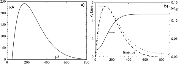
Arc motion in the unipolar mode is described by Eq. (2) and (3) given above for the bipolar regime. The typical discharge current waveform used here and shown in Figure 10a is taken from Kovalchuk et al. (Reference Kovalchuk, Kim, Kharlov, Kumpyak, Tsoy, Vizir and Zorin2008b). In the present work, an exact numerical solution of Eqs. (1)–(3) is found, in distinction with Kharlov (Reference Kharlov2010), where a constant mass for the piston was used. It was shown in Kharlov (Reference Kharlov2010) that in the case where mass is negligible, a good approximation can be obtained by taking the left side of Eq. (2) as zero, which results in the following formula for the spark channel velocity:
 $$v(t) = \sqrt {\displaystyle{{2IBl} \over {({{\rm \gamma}} + 1){{\rm \rho}} _1S}}} $$
(a) Typical discharge current; (b) calculated arc velocity and mass versus time [dash line Varc at α = 0, dot line Varc at α = 6 × 10–12 kg/(A2 × s) solid line plasma piston mass at α = 6 × 10⁻¹² kg/(A2 × s)].

Figure 10b presents a comparison of arc velocity, derived from Eq. (4), with a numerical solution of Eqs. (1)–(3) for a value of α = 6 × 10⁻¹² kg/(A2 × s). The calculated temporal behavior of the plasma piston mass is also shown in Figure 10b. It can be seen from the figure that although the piston mass increases sharply during motion, the velocity curve is close to the variant of zero mass. This is validated using the approximation in Eq. (4) for estimation of the plasma channel displacement over a wide range of acceleration regimes. The mean velocity calculated over a time interval of 800 µs (the full pulse length of the discharge current in Fig. 10), varies in the range 1.67–1.9 km/s for the curves in Figure 10b. We note here that the experimental mean velocity of arc motion measured in Kovalchuk et al. (Reference Kovalchuk, Kim, Kharlov, Kumpyak, Tsoy, Vizir and Zorin2008b) was ~1.8 km/s, which is in fair agreement with both theory and experiment. There are also good agreements with the results reported in Zhukov et al. (Reference Zhukov, Reznikov, Kurakin and Rozov2007), where the motion of the plasma channel in linear rail geometry was investigated.
Heating of electrodes
The heat flux to the electrodes for the plasma moving along z can be written as
 $${\rm \delta} Qe(z(t)) = (Ue \times I(t) + \Pr \times Se) \times {\rm \delta} z/v(t)$$
Here, Ue is the voltage drop at the cathode (anode) sheath, Pr is the total radiation power density, and Se is the area of the cathode (anode) arc spot. The treatment of radiation is rather complicated. Partial capture of the ablating material by the plasma channel leads to a plasma state involving a mixture of gas and metallic vapor. Addition of metal vapors not only increases the amount of radiated power but also increases the electrical conductivity in the zones surrounding the arc. These two effects tend to decrease the axis temperature of the arc. An excellent review of various aspects of the modeling of thermal plasmas (including high current electrical arcs) is given in Gleizes et al. (Reference Gleizes, Gonzalez and Freton2005). The emission consists of line radiation of atoms and ions and continuous radiation. Although line emission treatment is the most challenging, it must be considered since it is often the main component of a radiative energy transfer (Gleizes et al., Reference Gleizes, Gonzalez, Liani and Raynal1993; Cressault et al., Reference Cressault, Hannachi, Teulet, Gleizes, Gonnet and Battandier2008). Typical arc diameters at microsecond pulses, with a current of more than 100 kA, can be estimated as 15–20 mm. An arc diameter of 15 mm was assumed in our calculations, corresponding to the arc trace width observed in Kovalchuk et al. (Reference Kovalchuk, Kim, Kharlov, Kumpyak, Tsoy, Vizir and Zorin2008b). The current density exceeds 20 kA/cm2 in all the regimes considered in the present work, and thus a thermal plasma is a valid approximation. The cathode spot area is significantly less than the total surface area of the plasma channel, meaning that the radiative energy loss is much greater than the energy delivered to the electrodes.
Based on Eq. (5), the heating of the electrodes can be considered uniform along the electrodes, since from Eq. (4), the velocity is proportional to the current. This allows for a straightforward calculation of the temperature distribution at the electrodes using the heat equations.
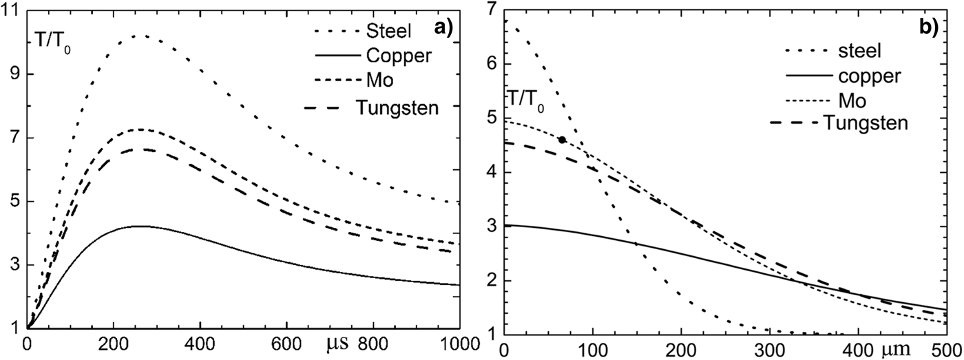
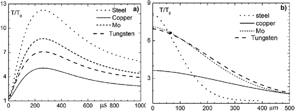
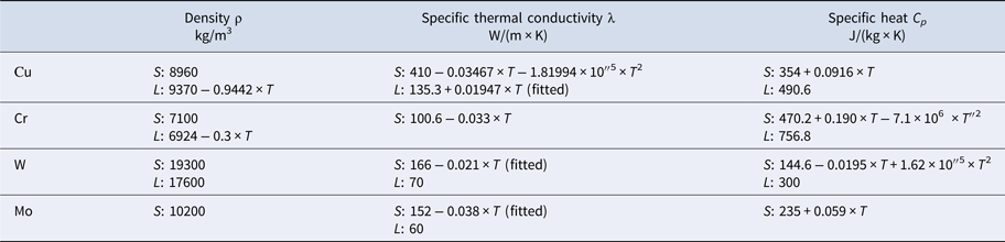
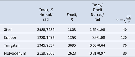
The materials considered here are stainless steel (Cr/Ni/Ti 18/10/0.6÷0.8), copper, molybdenum and tungsten since these are widely used for the manufacture of electrodes. Table 3 shows the physical (temperature dependent) properties of these materials. The physical parameters were taken directly from the experimental results (Dieter et al., Reference Dieter, Henry and Lampman1979; Weast, Reference Weast1988; Smithells, Reference Smithells2004). Table 4 compares the maximum temperature at the electrode surface Tmax for steel, copper, molybdenum, and tungsten with the melting temperature Tmelt for these materials (both with and without taking the radiation into account). The diffusion length δ is also shown here. It can be seen from Table 4 that for the steel electrode, the maximum temperature at the surface significantly exceeds the melting temperature, while for all other materials Tmax ⩽ Tmelt. Figure 11a demonstrates the evolution of the surface temperature with time and Figure 11b shows the temperature distribution versus depth at time t = 600 µs (i.e. 600 µs after the arc passes a given z position). It can be seen here that the temperature distribution is more relaxed in copper at t = 600 µs, and remains steep in steel. Hence, copper can be considered a more favorable material for electrodes than stainless steel due to its high thermal conductivity. It can be seen from Figure 12 that taking the radiation heating into account results in a ~20% increase in temperature.
(a) Evolution of the surface temperature versus time, (b) Temperature versus depth distribution at t = 600 µs for steel, copper, molybdenum, and tungsten electrodes without taking radiation into account.

(a) Evolution of the surface temperature versus time, (b) Temperature versus depth distribution at t = 600 µs for steel, copper, molybdenum, and tungsten electrodes taking radiation into account.

Physical parameters of Cu, Cr, W, Mo (S – solid state of the material, L – the liquid one)

Maximum temperature on the electrode surfaces

Summary
A simple and effective model is developed here to study the behavior of high-velocity plasma arc motion in linear rail geometry, in both the oscillatory and unipolar regimes of a capacitor bank discharge in a high-pressure gas at high current and high charge transfer pulses. The main features of the model are the time-dependent thermal coefficients, which take into account both the ablation of the electrode material with an increase in the arc mass and the radiation of the plasma channel. Arc motion and electrode heating were investigated in terms of their dependence on the current and charge transfer at very different pulse shapes, and reasonable agreement with experiment was demonstrated. This approach can also be employed for the simulation of many types of plasma accelerators, magnetically driven arcs, and plasma-driven electromagnetic launchers.
Author ORCIDs
A.V. Kharlov, 0000-0003-0849-1636
Acknowledgment
This work supported was by Russian Foundation for Basic research grant 18-08-01209