I. INTRODUCTION
The shape memory effect (SME) of Fe–Mn–Si alloy is attributed to the stress-induced martensite transformation from a parent γ phase (fcc) to an ε phase (hcp). Reference Sato, Chishima, Soma and Mori1 Fe–Mn–Si-based shape memory alloys (SMAs) have received considerable attention due to their low cost, good workability, good machinability, and good weldability. These alloys also show great promise as a possible alternative to expensive Ti–Ni SMAs for constrained recovery applications in various industrial sectors, such as the construction, chemical, and petrochemical industries. Reference Otsuka and Wayman2
Despite their unique properties, Fe–Mn–Si alloys are currently used only in few practical applications. Their low recoverable strains and poor corrosion resistance are the main limiting factors for the use of Fe–Mn–Si SMAs in engineering applications. Much attention has focused on achieving remarkable shape recovery through suitable additions of alloying elements while maintaining or even improving the corrosion resistance. In the past 30 years, two typical groups, namely, Fe–28Mn–6Si–5Cr with a fairly good SME but poor corrosion resistance and Fe–14Mn–5Si–9Cr–5Ni with good corrosion resistance but poor SME, have been developed. Good corrosion resistance and excellent shape recovery have been achieved by means of changing the composition and training. Several studies also have been made to investigate their corrosion behaviors. Reference Söderberg, Liu, Yakovenko, Ullakko and Lindroos3–Reference Della Rovere, Alano, Silva, Nascente, Otubo and Kuri6 However, due to the cost and processing difficulty of training, low recovery stress and the high annealing temperature for recovery, it has not been practically used for commercial technical applications so far apart from some trail engineering.
Since Kajiwara and coworkers had made a breakthrough to improve SME by producing small NbC precipitates after aging without training, Reference Kajiwara, Liu, Kikuchi and Shinya7–Reference Baruj, Kikuchi, Kajiwara and Shinya9 the conventional alloy involving second phase particles to the γ matrix have been drawing much attention again. Wen et al. investigated the effect of Cr23C6 carbide precipitation and the SME was enhanced in Fe–14Mn–5Si–8Cr–4Ni–0.16C alloy. Reference Wen, Xiong, Li and Zhang10 Dong et al. found that the addition of VC precipitates also greatly improved the shape recovery. Reference Dong, Klotz, Leinenbach, Bergamini, Czaderski and Motavalli11 Susan et al. also reported on the effect of VN precipitates on the improvement of the shape recovery, the conditions for forming VN precipitates in the grains were made clear in their work. Reference Farjami, Hiraga and Kubo12,Reference Kubo, Nakamura, Susan and Maruyama13 However, most of the researches were related to improving the shape memory strain and recovery, rarely focusing the influence of aging on corrosion resistance. Consequently, corrosion behaviors of the Fe–Mn–Si-based shape memory alloy with second phase precipitates should be investigated to extend their applications.
In view of the above, a small amount of C, N, and V was added into the Fe–Mn–Si–Cr–Ni-based alloy. Aging treatment was carried out on the newly developed shape memory alloy for various times. The influence of aging on the microstructure, phase composition and thus, on its SME of the alloys was investigated. The corrosion behaviors in 0.5 M H2SO4 and 3.5% NaCl solutions of the alloys were evaluated based on potentiodynamic polarization and electrochemical impedance techniques.
II. EXPERIMENTAL DETAILS
The alloy of Fe–20Mn–5Si–10Cr–5Ni–0.7V–0.2N–0.1C (mass%) was prepared by vacuum induction melting under an argon atmosphere. After homogenization at 1473 K for 5 h, the ingot was hot-forged at 1373 K into a plate with a thickness of 20 mm, and then underwent solution treatment at 1423 K for 5 h. From the as-solution plate, strips were cut with the size of 100 mm × 3 mm × 0.7 mm for SME tests, and slices were cut as 10 mm × 10 mm × 2 mm for corrosion tests. The samples were aged at 1073 K for 15 min to 24 h, followed by quenching in water.
The shape recovery was characterized by bending tests. All samples were bent to a certain angle corresponding to a maximum strain of 4%. Recovery was induced by heating to a certain temperature and subsequent cooling to room temperature. The shape recovery ratio was determined by measuring the returning angle of the sample after heating.
For electrochemical measurements, the samples were mounted in polyester resin after establishing the electric contact, taking special care to avoid the presence of crevices. The exposed area was 1.0 cm2. All the electrochemical measurements were taken at 25 °C in newly prepared naturally aerated solution of 0.5 M H2SO4 and solution of 3.5% NaCl. A standard three-electrode electrochemical cell was used with a platinum counter electrode and a saturated calomel reference electrode (SCE) connected to a Gamry Reference 1000 potentiostat. Three sets of measurements of each sample were taken and the average value was considered. Before the potentiodynamic polarization and EIS measurements, the samples were wet ground with silicon carbide paper up to #2000 grit, washed in distilled water, and immersed in the electrochemical cell. The samples were subsequently subjected to open circuit conditions until a steady-state potential was reached. This procedure was accomplished in 30 min and the potential value obtained was considered as the corrosion potential (E OC). Potentiodynamic polarization scans were carried out at a sweep rate of 0.1667 mV/s, starting from a potential of 200 mV below E OC, to a potential of 1200 mV versus SCE. The EIS measurements were taken with a 10 mV amplitude signal at an applied frequency ranging from 100 kHz to 10 mHz.
The martensite phase transformation temperature, M s, of samples was measured in a physical properties measurement system Quantum Design, PPMS-9 by using the four-point probe method. X-ray diffraction (XRD, Rigaku D/max 2500 Cu Kα) was used for phase identification. The microstructure was observed using optical microscope (OM), scanning electron microscope (SEM), and transmission electron microscope (TEM), respectively. To prepare foils for TEM observation, the samples were ground mechanically and then polished in a mixed solution of sulfuric acid and methanol (20%) at −20 °C using a twin jet polisher.
III. RESULTS AND DISCUSSION
A. Influence of aging on SME
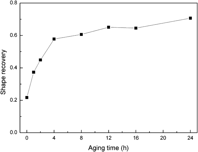
Figure 1 shows the shape recovery ratio of the samples with different aging times. It can be seen that the shape recovery ratio increased with the increasing aging time and reached its maximum value 72% (4% deformed at room temperature and followed by heating up to 573 K) at 24 h. A sharp increase of shape recovery ratio occurred in the aging time from 0 to 4 h, over which aging had little effect on SME. With the aging time prolonging, the shape recovery ratio increased slightly and steadily, and reached 72% (compared with that of 21% for unaged) at 24 h.
Shape recovery of the samples with different aging times at 1073 K.

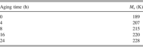
Table I gives the M s temperatures of the samples before aging and after aging for different times. Distinctly, the M s temperatures of aged samples were higher than that of unaged. Meanwhile, by prolonging the aging time, the M s temperature exhibited an increase, which can be attributed to the precipitation of V(CN) and Cr23C6 particles. That is, the growth of V(CN) and Cr23C6 precipitates will consume excess C, N, V, and Cr in the austenite matrix, resulting in the increase of M s temperature. Therefore, the formation of stress-induced martensite was easier, which can contribute to the improvement of the SME.
M s temperatures of the samples with various aging times.

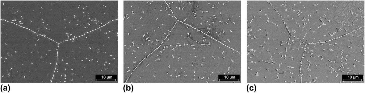
Figure 2 shows the SEM image of samples with different aging times. It can be noted that precipitates were formed in the matrix, the amount and size of the precipitates gradually increased with increasing aging time. With aging time prolonging, more and more precipitates aggregated at the grain boundaries rather than inside the grain. It is obvious that, compared to those in further aged samples, the precipitates in samples aged for 2 and 8 h were less with smaller size. Most of the precipitates have average diameters between 0.2 and 1 μm. Particles with average diameter more than 1 μm were only found in samples aged for 24 h. As shown in Fig. 2(c), the larger particles along the grain boundaries were around 2–4 μm. The sample with aging time of 24 h obtained a perfect shape recovery ratio (see Fig. 1), indicating that large particles at the grain boundaries would not adversely affect the SME.
SEM micrographs of samples aging at 1073 K for (a) 2 h, (b) 8 h, (c) 24 h.

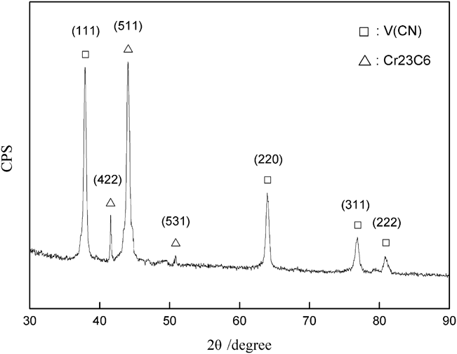
According to the alloy composition, the element content of the second phase is just a small amount (1% mass), which is too small to be detected by XRD. Therefore, the particles were extracted by immersing the sample into dilute sulfuric acid (20%). Figure 3 shows the XRD pattern of the extracted particles, which can be identified as the second phases of V(CN) and Cr23C6.
XRD pattern of the extracted compound from the sample aged at 1073 K for 24 h.

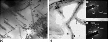
Figure 4 shows TEM micrographs of a sample aged at 1073 K for 30 min. It is observed that clusters of fine particles were associated with many stacking faults. The stacking faults were probably artifact produced during the sample preparation as the result of low stacking energy. The large elastic strain around the precipitates promoted the formation of new stacking faults, growing along an orientation different from the preexisting one. It is assumed that the precipitates, which nucleated on the top of stacking faults can act as nucleation sites of stacking faults with different orientation, the γ to ε transformation would in consequence take place while the sample underwent high enough stress. The interface energy of the particles and matrix can promote the formation of stacking faults and ε-martensite. Figure 4(b) shows a high-resolution electron micrograph of the precipitates observed in [001] zone. The precipitates were formed coherently to the matrix phase with a rectangular projected shape. Nanometric scale V(CN) and Cr23C6 precipitates as those pointed to by black arrows in the figure can be recognized by their corresponding diffraction patterns.
TEM micrographs of a sample aged at 1073 K for 30 min. (a) Overview of the precipitates at stacking faults, (b) high-resolution electron micrograph of V(CN) and Cr23C6 particles, (c) and (d) the corresponding diffraction pattern of the precipitates indicated by the black arrow.

It has been reported that defects in the austenite could act as nucleation sites for the precipitates in other Fe-based alloys. Reference Dutta, Palmiere and Sellars14,Reference Rainforth, Black, Higginson, Palmiere, Sellars, Prabst, Warbichler and Hofer15 The deformation will preferentially induce some martensite in a favorable orientation relative to the stress. The stress-induced martensite will then preferentially introduce ε/γ interfaces and stacking faults inside. Thereby, the nanosized particles inside the grains mainly precipitate accompanying the stacking faults and dislocations, resulting in many Shockley partial dislocations. Therefore, a direction sequence of the high density nucleation sites for the ε-martensite will be generated. Furthermore, the small precipitates could strengthen the matrix alloy, act as nucleation sites for γ (fcc) → ε (hcp) phase transformation and impede the extension of the Shockley partial dislocation. As a result, the shape memory property was remarkably improved.
B. Influence of aging on corrosion resistance
1. Corrosion behavior in 0.5 M H2SO4 solution
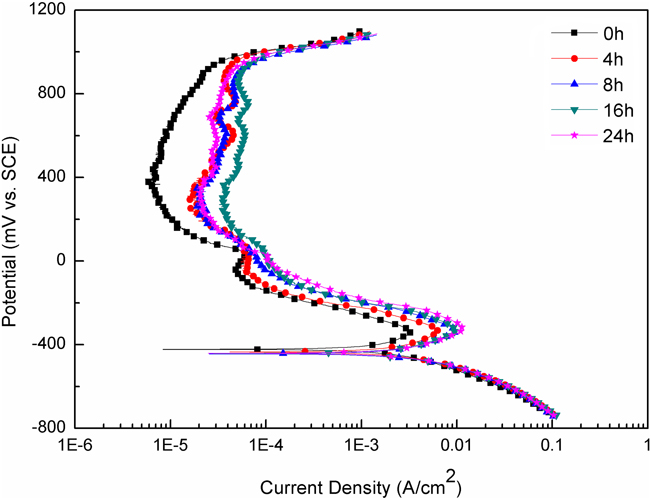
The E corr of the samples was monitored for 30 min after immersion in 0.5 M H2SO4 solution. All the samples initially showed a rapid change in potential, afterward, a gradual increase until the potential stabilized. The values of the samples were in the order of unaged (−427 mVSCE) > 4 h-aged (−433 mVSCE) > 24 h-aged (−438 mVSCE) > 16 h-aged (−440 mVSCE) > 8 h-aged (−447 mVSCE), indicating that aging treatment made the alloy more active and further aging seemed better.
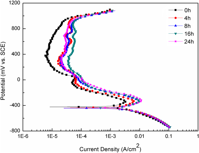
Figure 5 shows the potentiodynamic polarization curves of all the samples in 0.5 M H2SO4 solution. Note that the solution treated sample and the aged samples showed a very different anodic behavior in the active dissolution region, which may be attributed to the precipitates and chemical composition of the matrix, although their respective curves showed similar passive regions. The different electrochemical parameters determined from this plots are presented in Table II. Though the cathodic polarization behavior is the same for all samples, the anodic polarization behavior is obviously different in terms of the passivation potential (E pp), the critical current required for passivation (i crit) and the passivation current (i pass). The i pass of the four aged samples was found to be much higher than that of the sample before aging (6.11 × 10⁻⁶ A/cm2). According to the results of a previous study, Reference Söderberg, Liu, Yakovenko, Ullakko and Lindroos3 the addition of N and V might have a beneficial effect on the corrosion resistance of the FeMnSiCrNi shape memory alloy. Therefore, it was easier for the unaged sample to form passive film when compared to the aged ones. This behavior can be attributed to the V(CN) and Cr23C6 precipitates, which depleted the Cr, V, and N content in the austenitic matrix and changed the single austenite phase to the dual phase structure of austenite and precipitates. However, the variation in aging time had a limited effect on the i crit. On the other hand, the passive current density (i pass) of all the aged samples was nearly equal to each other but almost a decade higher than that of the unaged. This shows that the different periods of aging treatment did not affect the passive current density and the passive films formed on unaged sample were more protective. The corrosion current density (i corr), obtained from the linear polarization measurements, is presented in Table II. The higher i corr of the samples after aging indicated the lower corrosion resistance of these samples, when compared to the unaged. Interestingly, the 24 h-aged sample was observed to have a higher E corr value and a lower i pass value than those of the samples aged for 8 and 16 h. This can be ascribed to the difference in the distribution of the precipitation elements due to various aging times. Since further aging treatment on the sample could result in superior homogenization effect, sample with the longest aging time (24 h) exhibited a reversion of the corrosion resistance.
Potentiodynamic polarization curves obtained from samples with various aging times in 0.5 M H2SO4 solution.
Electrochemical parameters of the samples after different aging treatments in 0.5 M H2SO4 solution.

2. Corrosion behavior in 3.5% NaCl solution
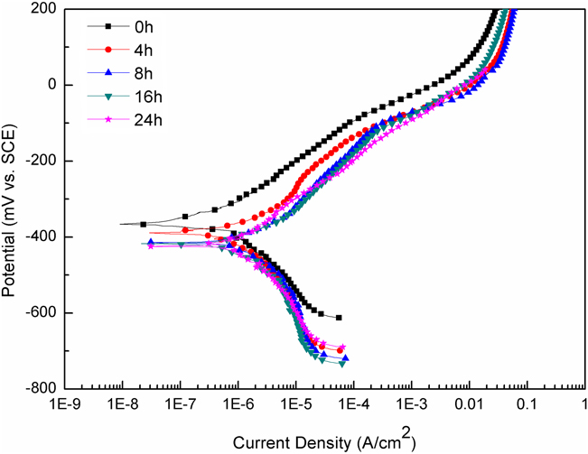
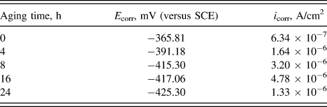
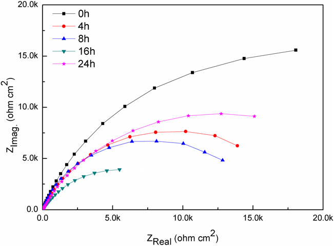
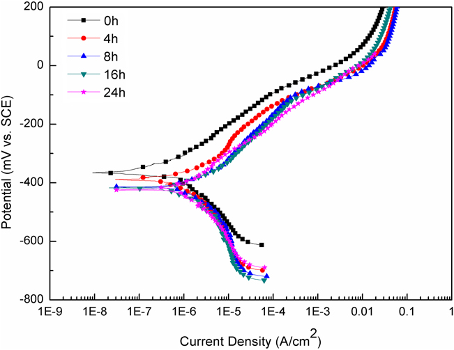
The corrosion resistance of the samples before and after aging in 3.5% NaCl solution was compared by polarization curves in Fig. 6. The corrosion of the samples occurred by uniform general dissolution and did not show a passivation, which is in agreement with the results from the previous study. Reference Söderberg, Liu, Yakovenko, Ullakko and Lindroos3 The fitting results (E corr and i corr) of the polarization curves are listed in Table III. The unaged sample exhibited a higher corrosion potential than the samples subjected to aging, indicating that the precipitated particles made the alloy more active in 3.5% NaCl solution. By prolonging the aging time, the E corr displayed a gradual decline until the value reached −425.30 mV at 24 h, compared to −365.81 mV before aging. Furthermore, the i corr of the sample increased with the increasing aging time before 16 h, while exhibited an obvious decrease at 24 h. Figure 7 illustrates the Nyquist plots of the samples in 3.5% NaCl solution at their respective E OC. The Nyquist plots show different capacitive semi-arcs, the unaged sample showed capacitive semi-arc with much bigger diameter than that of the samples subjected to aging treatment. Note that the 16 h-aged sample had the smallest diameter of capacitive semi-arc, the diameter of capacitive semi-arc of 24 h-aged sample was bigger than that of the samples aged for 4, 8, and 16 h. The results indicated that aging treatment on the alloys reduced the corrosion resistance, while aging for 24 h might weaken the effect, as the polarization curve analysis demonstrated above.
Potentiodynamic polarization curves obtained from samples with various aging times in 3.5% NaCl solution.
Electrochemical parameters of the samples after different aging treatments in 3.5% NaCl solution.

Nyquist plots obtained from samples with various aging times in 3.5% NaCl solution at the E OC.
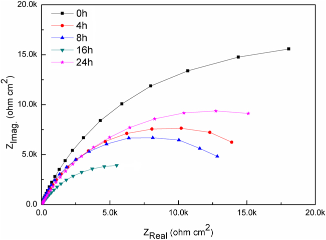
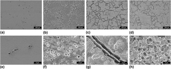
Figure 8 shows the surface morphology of the alloys after the potentiodynamic polarization test in 3.5% NaCl solution. As can be seen, there is no obvious corrosion attack observed from the low magnification morphology [Fig. 8(a)]. Whereas, few shallow pits are visible in the crystal grain from the high magnification morphology [Fig. 8(e)]. It indicates that only the crystal grains of the unaged sample suffered slight attack. In the case of the sample aged for 4 h, the surface presents uniform corrosion characteristics. Obvious corrosion pits can be observed in the crystal grains, and some particles possibly fall from there, but the grain boundaries did not suffer more severe attack. Most of the corrosion pits are shallow with a small dimension. However, the 16 h-aged sample exhibited the most severe attack, with intense corrosion clearly identifiable around the second phases and along the crystal grains. In the case of the magnified morphology of the grain boundaries [Fig. 8(g)], the width of the crevices along the grain boundaries is enlarged in comparison with that of 4 h-aged sample, and the diameter of the corrosion pits in the vicinity of the grain boundaries is approximately 2–3 μm. However, the corrosion morphology of 24 h-aged sample change for better in comparison with the sample aged for 16 h, and the crevices along the grain boundaries are shallow, as shown in Fig. 8(d).
Corrosion morphologies of the samples with different aging times. (a) 0 h, (b) 4 h, (c) 16 h, (d) 24 h, low magnification, and (e) 0 h, (f) 4 h, (g) 16 h, (h) 24 h, high magnification.

The corrosion morphologies are in good agreement with the polarization curves and Nyquist plots. The V(CN) and Cr23C6 second phases resulted from aging act as micro-cathodes and play a key role in accelerating the corrosion of the samples. The precipitates are more electrochemically stable than the austenite matrix. Thus, the V(CN) and Cr23C6 second phases act as micro-cathodes while the austenite matrix around the fine size particles acts as micro-anodes to form abundant corrosion pits. In the case of the unaged sample, severe corrosion around the grain boundaries is not found in Fig. 8(a). However, there are wide crevices observed along the grain boundaries of the 4 h-aged sample in Fig. 8(b). It indicates that the grain boundaries suffered severe attack due to the existence of the V(CN) and Cr23C6 second phases which can act as micro-cathodes to accelerate corrosion. In addition, the depth of the corrosion pits in the crystal grains and crevices along the grain boundaries of 16 h-aged sample [Figs. 8(c) and 8(g)] present a much larger scale compared with those of 4 h-aged sample [Figs. 8(b) and 8(f)]. On the other hand, the sample with aging time of 16 h exhibited the highest i corr among these alloys, as shown in Table III. It can be attributed to the more and larger precipitates on account of the longer aging time (16 h). Differently, severe corrosion is not found from the low magnification morphology [Fig. 8(d)] of the sample aged for 24 h. Meanwhile, the 24 h-aged sample had a dramatic decrease in i corr to 1.33 × 10⁻⁶ A/cm2, which is almost equal to that of the 4 h-aged sample (1.64 × 10⁻⁶ A/cm2). This can be ascribed to the preferable long-range diffusion of the precipitation elements due to the long aging time of 24 h, as the precipitations have reached saturation condition at 16 h. Therefore, the 24 h-aged sample displayed an improved corrosion resistance, in comparison with the samples aged for 8 h and 16 h.
IV. CONCLUSIONS
-
(1) The newly developed Fe–Mn–Si–Cr–Ni alloy containing C, N, and V elements exhibited excellent shape recovery properties with various aging treatments without any training process. The shape recovery ratio of the alloys increased with the increasing aging time and reached 72% (4% deformed at room temperature and followed by heating up to 573 K) when the sample was aged at 1073 K for 24 h. The XRD analysis and the TEM observation clarified the formation of nanosized V(CN) and Cr23C6 particles mainly precipitated with stacking faults and dislocation.
-
(2) The samples before and after aging showed a similar active region and passive region in 0.5 M H2SO4 solution. However, aging treatment reduced the corrosion resistance, the corrosion rate (i corr) of the aged samples was almost three times higher than that of the unaged.
-
(3) The samples showed poor corrosion resistance in 3.5% NaCl solution without passivity. The local corrosion occurred in the alloys and many corrosion pits were observed. After aging, the corrosion resistance of the samples reduced, which can be associated with the acceleration function of the V(CN) and Cr23C6 particles. These particles precipitated on grain boundaries or crystal grains both acted as micro-cathodes to accelerate corrosion. The more volume fraction of the V(CN) and Cr23C6 second phases can result in a worse corrosion resistance, while 24 h-aged sample exhibited a reversion of corrosion resistance, may be attributed to the improved distribution of the precipitation elements.
ACKNOWLEDGMENTS
The authors are grateful to the Natural Science Foundation of Tianjin (No. 13JCZDJC31900 and No. 14JCZDJC38700), China National Funds for Distinguished Young Scientists (No. 51325401), the National Nature Science Foundation of China (No. 51474155), and the International Thermonuclear Experimental Reactor (ITER) Program Special Project (No. 2014GB125006) for grant and financial support.