


I. INTRODUCTION
Since the invention of radar by Christian Hülsmeyer [Reference Skolnik1] more than 100 years ago, many new radar systems were and are built with increasing tendency to higher performance in all areas of remote sensing. The common trend for new systems is toward better performance in polarimetric and radiometric accuracy, sensitivity, operational mode complexity and of course the spatial resolution. To understand and analyses degrading effects for such future new systems, which become important due to the increase in complexity and performance, corresponding ground-based experiments are helpful. Besides exploring new imaging and signal processing techniques the new system GigaRad was developed and constructed at German Aerospace Center to allow the investigation of these topics, besides high-performance radar signature acquisition, respectively.
GigaRad is an experimental platform for exclusively ground-based measurements. In its basic modes the system works as pulse radar at a center frequency of 11 GHz with an instantaneous bandwidth of maximum 6 GHz using IQ modulation/demodulation, allowing the creation of high-resolution range profiles with a theoretical range resolution of 2.5 cm. By use of an ultra-stable oscillator the system is able to work as a synthetic aperture radar (SAR) [Reference Fitch2], or alternatively in an inverse synthetic aperture radar (ISAR) [Reference Mensa3] mode, intended to achieve a similar resolution in azimuth direction in both cases. To address many operational modes the system is designed as a multi-channel configuration. In the basic setup two transmit (TX) and two receive (RX) channels are implemented for simultaneous operation. This feature enables investigations on Multiple Inputs Multiple Outputs (MIMO) techniques as well as research on orthogonal waveforms or fully polarimetric signature measurements, for instance. By using a switch matrix, the system can be easily extended to a higher number of TX and RX channels.
Another interesting mode is a bi-static constellation, separating TX and RX antennas by up to several tens of meters. The basic radar hardware and the displaced TX power amplification, as well as the low-noise RX section, are then connected via an optical fiber enabling broadband low-loss transmission of the RF signals.
The high degree of digitization on TX and RX sections and the overall high-performance enables a wide variety of applications. A detailed description of the instrument, the error correction strategy, and some illustrative measurement results are presented next. Especially the huge bandwidth demands new strategies in calibration and investigations to overcome possible band gaps due to frequency regulations.
II. SYSTEM DESCRIPTION
The high degree of flexibility results in a very complex block diagram for the instrument. For clarity and basic understanding a simplified block diagram is shown in Fig. 1. The main functional parts of the instrument are:
-
• Arbitrary waveform generator,
-
• IQ transmit part,
-
• IQ receive part,
-
• High-speed data acquisition,
-
• Error correction network.
Simplified block diagram of the GigaRad instrument.

Purely digital signal generation is performed using a high-performance arbitrary waveform generator, providing a maximum data rate of up to 10 GS/s at 8 bits in amplitude resolution. This allows the required flexibility on TX side in order to perform simultaneously transmitted orthogonal waveforms as useful in MIMO applications [Reference Castellanos, Jirousek and Peichl4], and an advanced error correction strategy. Both output signals are coherently generated and fed to the IQ modulator. Then the signal is filtered, amplified, and transmitted. On the RX side the functional concept is similar, except the signal conditioning part before digitization. The main restricting factor for the maximum system bandwidth is the high-speed analogue-to-digital converter device providing a sampling rate of 8 GS/s providing an effective number of 5 bits in amplitude resolution. Hence, in order to fulfill the Nyquist criterion with some safety margins, the maximum analogue IF bandwidth is set to 3 GHz, being the same as the analogue 3 dB bandwidth of the digitizer's input RF section.
In order to generate technically the intended maximum bandwidth of 6 GHz, this overall range is split in an upper sideband (USB) and a lower sideband (LSB) around the center frequency of 11 GHz. The corresponding frequency plan of the radar system is depicted in Fig. 2. By that means the maximum IF bandwidth only has to be 3 GHz in order to achieve a maximum RF bandwidth of 6 GHz by frequency conversion. However, that procedure requires proper rejection of the image frequency. In order to maintain maximum system flexibility, the image rejection is realized in two different ways. On one hand a group of filters in the RF section of the TX and RX modules allows direct suppression of USB or LSB, respectively. On the other hand an IQ modulation (mod) scheme for TX and an IQ demodulation (demod) scheme for RX are implemented. Especially the IQ procedures require proper correction of imperfections to achieve the desired image rejection as described in Section III. Another very important issue for very high-resolution SAR applications is sufficient coherence and therefore stability of the local oscillator. In case of GigaRad the implemented phase-locked source offers excellent phase noise of −110 dBc/Hz at 1 kHz and spurious performance of better −80 dBc and can be additionally locked on an external ultra-stable oscillator, connecting both the digital and the frequency conversion sections, for further improved performance if required.
RF frequency plan of the GigaRad system.

Since the instrument is built as a multi-channel system, the RF parts of TX and RX sections are implemented twice. The presently realized state enables either use of 3 GHz bandwidth at full two-by-two channel operation, or use of 6 GHz bandwidth by pulse-to-pulse channel switching [Reference Anger, Jirousek and Peichl5].
The basic hardware setup of GigaRad is shown in Fig. 3. From bottom to top the single units are arranged in a 19″ rack. The high-power and low-noise amplification sections are excluded to allow a bi-static operation via optical transmission, so they are not shown in Fig. 3.
Basic hardware setup of GigaRad.

Due to the complexity of the system, the different filter constellations, the error correction, and the required timing accuracy, an Erasable Programmable Logic Device and a micro controller are intended to control the whole instrument. That unit is presently under development as well as the displaced TX and RX extensions. The extensions are shown in Fig. 4 in a simplified block diagram. Especially for high-power applications, the TX power amplifier should be as close as possible to the antenna maximizing the radiated power. The same approach is valid for the RX path, where the low-noise amplification should be close to the antenna port maximizing the signal-to-noise ratio (SNR). An optical link connects the extension and enables a separation of several tens of meters. However, not only the RF signal must be transmitted, but also the time sensitive control signals for duty cycle modulation of a traveling wave tube amplifier have to be connected via a high-speed real-time bus. Obviously for calibration purposes an optical link is also necessary between the two extensions to enable the comprehensive corrections described in the next section.
Simplified block diagram of the extended GigaRad instrument.

III. ERROR CORRECTION AND ABSOLUTE CALIBRATION
As described in Section II, proper rejection of image frequencies is necessary for high-quality images. Therefore in a first step the error correction for the IQ sections is performed. The instant high IF bandwidth suggests an image rejection concept using connector-based components instead of integrated circuits. The drawback here is higher effort in accounting for the different components. In Fig. 6 the main strategy is illustrated graphically. First of all the local oscillator signals are adjusted with manual phase trimmers to 90° phase difference at the mixer diodes of TX and RX sections (path 1 shown in grey). This is the only step where additional external hardware is required. Notably in this step both IQ sections for TX and RX are operated as down converters, which is possible due to given reciprocity of the mixer devices. For the determination and trimming of phase and amplitude errors, an external signal now is connected at the mod/demod summation port in TX and RX section (right ends of paths 2 shown in green). Then this signal is analyzed at the left ends of green paths in TX and RX section using an oscilloscope, and the phase trimmers of path 1 are adjusted accordingly (Fig. 5).
System correction strategy (1) phase adjustment for the local oscillator signal in IQ modulation and demodulation, (2) amplitude and phase correction of the mod/demod sections, (3) amplitude and phase correction of the overall path.

Normalized logarithmic ISAR image and range profile of a 20 cm trihedral without correction of the instrument imperfections.

In a second step I and Q paths are aligned separately using the different filters for the USB and LSB (path 2 and 3). Since the signal is sufficiently rejected in the unwanted frequency range by the filters, only one channel of the arbitrary waveform generator has to be used to compare the sampled signals in I and Q channels for amplitude and phase differences in the demod part. The signal is thereby routed through the calibration path including the coupler right before the transmit antenna and the switch after the receive antenna. A similar procedure is used for proper alignment of both AWG output channels.
In a third and last step the overall frequency response in TX and RX chain is aligned with respect to phase, group delay, and amplitude (green and orange paths). Due to the high relative and absolute bandwidth of 54%, i.e. 6 GHz, the accumulation of gain variations of all devices results in a maximum amplitude difference of more than 10 dB. Hence, in a final version of the instrument, an additional equalizer filter is intended to reduce the bulk of amplitude variation for residual minimum variation of SNR over frequency.
Due to the large bandwidth, the frequency response of the antennas has to be considered, and that is done in the final step of the calibration. To achieve similar resolution in range and azimuth direction by SAR imaging, the maximum azimuthal observation angle has to be in the order of 30°. Therefore, in a Stripmap SAR measurement, the antenna pattern has significant impact on the amplitude distribution of the final image and thus has to be corrected for by an appropriate antenna model. Additionally, the antenna gain differs considerably within the wide frequency range. Hence, external calibration with a well-known reference target has to be used to compensate for that, and to provide the absolute calibration on radar cross-section (RCS).
IV. VERIFICATION OF ERROR CORRECTION AND ABSOLUTE CALIBRATION
A radiometric calibration is necessary to retrieve absolute RCS values of the observed object or scene. Usually, this is performed by comparing a previously measured reference object with sufficiently known RCS to the unknown data. For reduction of clutter and noise effects usually a point source having a sufficiently high RCS value is used. A trihedral reflector is the most common device. The advantage here is the relatively high RCS compared with its small geometric dimensions associated with a wide aspect angle of almost constant RCS level. A normalized high-resolution ISAR image of a trihedral reflector with an inner length of 20 cm and a RCS value of 9.5 dBm2 at 11 GHz is shown for the uncorrected system in Fig. 6 and for the corrected one in Fig. 7. The measurement was performed according to an ISAR geometry described in Section V. The uncorrected point source response shows a very asymmetric behavior especially in range direction, which is even more visible in the centric range profile. The first sidelobes at a level of about −5 dB are much too high as compared with the theoretical one of −13.2 dB. Even more severe is the degradation of the range resolution by a factor of roughly 2. Using now the correction method described in Section III, the point source response follows closely the sinc2 ((sin(x)/x)2) function as expected for an ideal instrument. Still there are some differences visible in the high-resolution image, e.g. the nulls of the response function are not formed as for an ideal sin c 2 function, and some asymmetry in the profile is still present. Here it should be noted that it is hard to generate an ideal trihedral in practice, as assumed for the ideal computations, since edge effects and the surrounding contribute to the signature as well and are hard to suppress completely.
Normalized logarithmic ISAR image and range profile of a 20 cm trihedral with applied correction of the instrument imperfections.

Another issue for broadband systems is the frequency dependence of the target RCS. The maximum RCS value of a trihedral of inner length a is proportional to the square root of the frequency f [Reference Nathanson, Reilly and Cohen6] as follows:
 $$\sigma _{corner} = \; \displaystyle{4 \over 3}\pi \displaystyle{{a^4 \;f^2} \over {c_0 {}^2}}.$$
Observing the back scattered power spectral density PSD r (f) from the trihedral according to the radar bandwidth, the average processed power level for the instrument is the integral mean value for the frequency band from f min to f max :
 $$P_r = \int {PSD_r (f)\,{\rm df}} \propto \displaystyle{1 \over {f_{max} - f_{min}}} \int_{f_{min}} ^{f_{max}} {\sigma _{corner} (f){\rm df}}.$$
Since the received power is proportional to the actual RCS, spreading in case of the GigaRad instrument across a bandwidth of 6 GHz, the difference between the theoretical mono-frequent RCS at center frequency RCS mono and the mean integral value RCS mean for a trihedral with an inner length of 1 m is at least RCS mono /RCS mean ≈ 0.1 dB. Furthermore the ratio of RCS for the highest and lowest frequency is given by σ(f max )/σ(f min ) = (f max /f min )2, resulting in an instantaneous SNR difference of about 3 or 4.9 dB, respectively, for a frequency range of 8–14 GHz during the chirp reception. Not only the frequency dependence, but also the aspect angle of the observation, i.e. the main parameter enhancing the azimuth resolution, affects the absolute RSC value to be considered in a broadband instrument. The azimuth resolution δ az for wavelength λ = c 0/f, c 0 ≈ 3 × 10⁸ m/s, can be approximated by
 $$\delta _{az} = \displaystyle{\lambda \over {4\sin \left( {\Delta \Theta /2} \right)}},$$
considering a constant amplitude of all received pulses along the aspect angle range ΔΘ. Now for the trihedral the variations of the reflected power ΔP with aspect angle Θ within the observation angle interval ΔΘ can be approximated to [Reference Gallman7]:
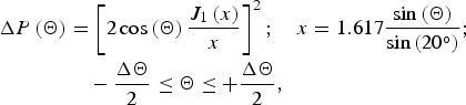 $$\eqalign{\Delta P\left( \Theta \right) & = \left[ {2\cos \left( \Theta \right)\displaystyle{{J_1 \left( x \right)} \over x}} \right]^2 ;\quad x = 1.617\displaystyle{{\sin \left( \Theta \right)} \over {\sin \left( {20^{\circ}} \right)}}; \cr & \quad - \displaystyle{{\Delta \Theta} \over 2} \le \Theta \le + \displaystyle{{\Delta \Theta} \over 2},} $$
where J 1 is the Bessel function of the first order. Hence, for similar range and azimuth resolution of 2.5 cm, ΔΘ ≈ 31° is required and consequently the power drop from maximum to minimum RCS is about ΔP(Θ = 0°)/ΔP(ΔΘ/2) ≈ 2.1 dB. Considering such a weighting of the trihedral response, the azimuth width of the SAR point source response is slightly widened and hence the corresponding observed azimuth resolution decreased. This widening of the main lobe also introduces a reduction of the peak RCS value of 0.7 dB, reducing even more the radiometric accuracy.
The effects of a reduction in radiometric accuracy can be corrected by introducing the equivalent RCS as proposed in [Reference Döring, Looser, Jirousek and Schwerdt8]. The impacts on the shape of the point source response can only be compensated by an accurate knowledge of the target signature behavior and a corresponding inverse filter implementation in the SAR processor. So, for calibration purposes it would be preferable using a target with a frequency and observation angle independent response. The only object fulfilling this requirement is a perfectly conducting sphere with a radius a≫λ, thus providing RCS in the optical region [Reference Skolnik1]. There the sphere has no frequency and angle dependence, but the RCS value for a reasonable size of the sphere compared with a trihedral is very low, i.e. σ sphere = πa 2. So the influence of clutter, noise, and interference signals can be quite high. However, for a SAR processor independent calibration of the GigaRad system, a sphere with 0.3 m diameter was measured in a configuration as shown in Fig. 8. The sphere was mounted on a polypropylene rope in several meters height above the radar instrument reducing previously mentioned effects to a minimum. Here the far-field condition was just kept for all frequencies. In order to achieve a two-dimensional impression of the sphere's point source response, a virtual ISAR image was performed by azimuth processing of N measurements of the identical range profile, N being the same number as it would have been for true azimuth sampling. The result is shown in Fig. 9, depicting an almost ideal point source response with 2.5 cm range resolution, 13.2 dB peak-to-sidelobe ratio (PSLR) and an integrated-sidelobe ratio (ISLR) of 10.7 dB. Using the sphere's range profile as a standard response, it was possible to verify the absolute calibration within 0.3 dB accuracy.
Photograph of the absolute calibration setup using a metallic sphere of 30 cm diameter, being loosely hanged up on a polypropylene rope at about 9 m distance to the radar antennas.

Normalized logarithmic ISAR image and centric range profile from measurements of the sphere of Fig. 8. For azimuth processing just a set of independently measured range profiles of identical angle Θ = 0° have been used.

V. MEASUREMENT RESULTS
Experimental verification of the GigaRad performance with respect to imaging capabilities and error correction was done by ISAR measurements on a tower-turntable arrangement [Reference Kempf, Peichl, Dill and Suess9] as shown in Fig. 10. TX and RX antennas are arranged at an elevated position and the distance between radar antennas and turntable was about 24 m. As RX antenna a standard gain horn and as TX antenna a parabola reflector with wideband feed was used providing a narrower beam. The frequency-dependent phase center spread of the antennas was corrected by means as described in Section IV. The incidence angle for that constellation was about 58°. For TX signal, a linearly frequency modulated up-chirp using a bandwidth of 6 GHz has been selected in order to obtain range profiles at highest possible resolution. As mentioned earlier the azimuth observation angle was chosen to 31° for equal resolution in range and azimuth direction.
Measurement configuration of the tower-turntable arrangement used for ISAR imaging.

The ISAR imaging of a trihedral reflector as reported in Section IV can show the capability of the radar instrument and verify the expected system performance parameters. In realistic scenes many point sources as well as distributed scatterers are overlaying each other. In the turntable arrangement also the clutter of the surrounding area has a significant influence on the desired signal from the object. Compared with a trihedral reflector of strong RCS, a distributed target RCS of natural background like grass is much lower, but can become significant due to its large contributing area, as it is valid for the surrounding of the turntable. Therefore a high gain antenna is used for illuminating only the turntable area, in order to suppress as far as possible these signals right in the hardware configuration. On SAR processor level a suitable high-pass filter is used to reduce the impact of stationary objects as they come from residual turntable surrounding. The SAR processor used for azimuth focusing is based on the back-projection algorithm [Reference Ulander, Hellsten and Stenström10].
In Fig. 11(a) the arrangement of a bicycle lying on the turntable is shown as an interesting example for very high-resolution imaging of a distributed complex target. The measurement was performed using 6 GHz bandwidth and an output power of −20 dBm. The TX antenna has a gain of about 35 dBi and the RX antenna of 20 dBi. Three illustrated images represent results of different filters and different processing methods. The processed azimuth angle was chosen to 100° so that target structures which are reflecting only over a certain range of aspect angles become visible in the image in parallel. Usually almost no object beside a sphere has relevant signature contributions over the whole azimuth angle and the whole bandwidth [Reference Anglberger, Speck, Kempf and Suess11].
Measured ISAR results of a lying bicycle in a turntable arrangement. (a) photograph of the scene; (b) focused image using 6 GHz bandwidth; (c) focused image using 2 GHz bandwidth; (d) focused image using 6 GHz bandwidth and complex dual apodization.

Figure 11(b) was processed applying all corrections and calibrations discussed in Section III. Therefore the impulse response is almost ideal in the sense that the rectangular frequency behavior generates the best spatial resolution. Because of the very high-resolution, sufficient, SNR, and adequate clutter suppression, the image even appears similar to an optical image with a potentially high feature extraction capability. Many details can be identified like the wheels, the frame, the pedal, the seat or the suspension fork. If the same measurement would be performed using a bandwidth of 2 GHz, counting even today as very-high-resolution radar, the image would look like in the Fig. 11(c) for the identical processing. Although that result being of the highest quality, it is hard to identify the structures in the image for an untrained image evaluator. For many applications containing objects with dominant scattering centers, signature extraction using an algorithm called complex dual apodization is used to suppress sidelobes while simultaneously keeping maximum spatial resolution [Reference Kempf and Peichl12]. This algorithm was used in the Fig. 11(d) for the full bandwidth, now showing to some degree clearer distinction capabilities of certain structures than without filtering.
VI. CONSIDERATION OF FREQUENCY REGULATIONS
The technically feasible bandwidth of 6 GHz around X band can never be used in an open environment due to legal frequency regulations. The frequency band from 8 to 14 GHz is used for several other narrow-band applications and in parts exclusively reserved for some of them. As an example, between 8 and 8.5 GHz there are no radar applications allowed as well as for 9–9.2 GHz, which is reserved for air traffic control. Other services and applications are not restrictively excluded. Hence, for each experimental application the permission from the Federal Network Agency is necessary. So, depending on the geo-graphical location, the operation at different frequency sub bands is possible. This of course depends on the services in the area around the intended experiments. Also the radiated power level and the antenna gain are essential. If the radiating directions of the experiments can be adequately restricted, site permission can also help allocating more frequency range. Due to the highly digitized character of the instrument in TX and RX paths, especially the generation capability of any possible waveform, a frequency agile signal, depending on the specific restrictions of the installation site, can be transmitted. A typical frequency plan excluding the main forbidden bands is shown in Fig. 12. The impact of the gap in the lower frequency region around 9 GHz and the correspondingly reduced overall bandwidth are visible in the point source response shown in Fig. 13 for a ±10 m range and zoomed for ±1 m range in Fig. 14. The reduction of the bandwidth shifts the starting frequency to 8.5 GHz and affects only the range resolution of the radar. Due to the relative small reduction of 0.5 GHz compared with the total bandwidth of 6 GHz, the RCS amplitude reduction is also small. In contrast, the 200 MHz wide gap at 9 GHz increases the PSLR and the ISLR as visible in the point source response, being now 14.2 and 9.8 dB. The frequency band reserved for radio astronomy between 10.68–10.7 GHz is quite narrow and has only little impact. In general, the regulation of the spectrum of course degrades slightly the image quality, but the impact often can be tolerated and by using proper filtering like raised-cosine [Reference Barry, Lee and Messerschmitt13] the impact can be even reduced.
GigaRad frequency range 8–14 GHz showing notches used to investigate impacts of spectrum limited imaging performance.

Simulated response of a point source based on an ideal (blue) and a notched (red) frequency spectrum shown for ±10 m range.

Simulated response of a point source based on an ideal (blue) and a notched (red) frequency spectrum shown for ±1 m range.

VII. CONLUSION
In this paper the new multi-purpose and very-high-resolution ground-based radar instrument GigaRad operated in X and Ku band was presented. The broadband system characteristics, the flexible setup, the multi-channel capability, and the high degree of digitization allow a multitude of applications. In order to achieve the expected high-performance, the system has been extensively characterized and an appropriate error correction scheme has been implemented. The absolute calibration using a proper reference target and the azimuth and frequency dependency of a trihedral for wideband radar operation have been investigated. The arbitrary waveform generation enables system installation on almost any site by adapting the used frequency spectrum of the transmitted signal to the on-site frequency regulations, taking into account a degraded frequency response of the instrument. The experimental verification of the system performance, the very high-resolution imaging capability, and the necessary error correction algorithms have been exemplarily shown by ISAR imaging of a very complex target like a bicycle.
However, it should be mentioned that there are still some challenges to be solved adequately. That is at first order the huge amount of data (several Gigabyte per image) generated for a single image due to the high degree of digitization and the very high data rate of 200 Megabyte/s. Furthermore, the true capabilities and practical benefits of using multiple channels in TX and RX operation still have to be explored.
 Dr.-Ing. Matthias Jirousek received the diploma in 2003 and the Ph.D. degree in Electrical Engineering from the University of Karlsruhe, Germany, in 2012. Since 2003, he has been with the Microwaves and Radar Institute, German Aerospace Center (DLR), Wessling, Germany, where he is working on microwave sensor system development. He is responsible for the research on a passive microwave imaging experimental spectrometer system based on aperture synthesis. His present research concentrates on a highly digitized wideband radar instrument GigaRad and the development of precise and flexible active calibration targets for future satellite SAR calibration missions with a focus on absolute radiometric calibration.
 Sebastian Iff M.Sc received the Master degree in Electrical Engineering from the University of Applied Science Würzburg-Schweinfurt, Germany, in 2014. Since 2013 he has been with the Microwaves and Radar Institute at the German Aerospace Center (DLR) in Wessling, Germany, where he is working on microwave sensor system development. During his Diploma and Master thesis he investigated the calibration strategy for the GigaRad and the stability of SAR image quality parameters. His present research concentrates on the analysis of spaceborne SAR systems.
 Simon Anger M.Sc received the M.Sc. degree in Electrical Engineering from the University of Ulm, Germany, in 2012. Since 2013 he has been working as Ph.D. candidate for the Microwaves and Radar Institute of the German Aerospace Center (DLR), Wessling, Germany. His research focuses on wideband inverse synthetic aperture radar (ISAR) systems and digital data processing algorithms.
 Dr.-Ing. Markus Peichl received the diploma in 1990 and the Ph.D. in 1994 in Electrical Engineering, both from University of Karlsruhe, Germany. In 1990 he joined the Microwaves and Radar Institute of the German Aerospace Center (DLR), Wessling, Germany, and in 1998 he became the head of the Microwave Sensors Group. His present activities cover the development and construction of innovative and advanced radiometer and radars systems for experimental and operational purposes with respect to future space-borne, airborne or ground-based remote sensing projects, research on advanced image reconstruction methods, and the investigation on possible applications for security and safety.



