
Introduction
Because of increased energy demands and climatic concerns, efforts are being made to improve the efficiency of thermal and nuclear power plants. Hence, the future innovative nuclear reactor requires structural materials with characteristics such as high temperature structural stability (975–1025 K); better dimensional stability with or without the application of load; and acceptable mechanical properties such as tensile strength, fracture toughness, and creep resistance after aging; and better resistance to severe corrosive reactor environments while handling the reactor coolants and other processing fluids [Reference Yvon and Carre1, Reference Murty and Charit2, Reference Zinkle and Ghoniem3].
High-entropy alloys (HEAs) are developed based on the novel concept of multi-principal elemental alloying and are currently gaining worldwide attention. HEAs are a simple substitutional solid solution with a single crystal structure or a combination of simple crystal structures, such as face-centered cubic (fcc), body-centered cubic (bcc), or hexagonal closed pack (hcp) structures, instead of the formation of complex intermetallic compounds. Formation of the simple solid solution is attributed to the reduction in Gibbs free energy for the solid solution due to the enhancement in configurational entropy [Reference Gao, Yeh, Liaw and Zhang4]. Solid solution strengthening in HEAs is the combined effect of heavy lattice distortion, sluggish diffusion resulting from the difference in adjacent site element chemistry, atomic distortion, and cocktail effect; all these together lead to HEAs with superior mechanical properties than those of conventional alloys made of a single principal element [Reference Gao, Yeh, Liaw and Zhang4].
Recent studies on HEAs under a radiation-prone environment have been conducted with the view of their application in nuclear power plants. Guo et al. reviewed the formation rules of solid solutions and amorphous metallic glasses and suggested that atomic size plays a key role affecting radiation-induced crystalline–amorphous–crystalline transitions in HEAs [Reference Guo5]. Single-phase FeNiMnCr HEA was studied under irradiation at temperatures ranging from room temperature to 973 K, and the results evidenced sluggish grain boundary diffusion and no void formation under the irradiated conditions, with hardness increasing after irradiation [Reference Kiran Kumar, Li, Leonard, Bei and Zinkle6]. Egami and his colleagues proposed HEAs as eminent candidate materials for nuclear reactors and high-temperature environment structural materials based on first-principles calculations (density functional theory approach) [Reference Egami, Ojha, Khorgolkhuu, Nicholson and Stocks7]. The improved mechanical strength and irradiation resistance properties of HEAs are identified as a result of severe lattice distortion [Reference Egami, Ojha, Khorgolkhuu, Nicholson and Stocks7, Reference Owen and Jones8].
AlxCoCrFeNi-HEA is one of the alloy systems that has been studied in detail for its structural stability, mechanical and electrochemical properties, and possible applications in power generation sectors (such as ultra-critical thermal power plants, geothermal power plants, and nuclear power plants) [Reference Sokkalingam, Mishra, Cheethirala, Muthupandi and Sivaprasad9, Reference Xia, Yang, Yang, Liu and Zhang10, Reference Yang, Xia, Liu, Wang, Liu, Fang, Zhang, Xue, Yan and Wang11, Reference Chen, Shi, Yang, Liaw, Gao, Hawk and Qiao12, Reference Lyu, Fan, Lee, Wang, Feng and Liaw13]. Yang et al. studied the structural stability of Al(x=0.1,0.75&1)CoCrFeNi-HEA under a 3-MeV Au ion radiation environment. They mainly focused on the precipitation behavior of such materials under radiation doses. Single-phase Al0.1CoCrFeNi-HEA exhibited high phase stability under irradiation. No precipitation was observed in single fcc phase Al0.1CoCrFeNi-HEA, but in the case of other multiphase HEAs, the occurrence of phase separation and some ordered phases were noticed [Reference Yang, Xia, Liu, Wang, Liu, Fang, Zhang, Xue, Yan and Wang11]. Al0.1CoCrFeNi-HEA has been extensively studied for its microstructure evolution and corresponding properties at room and elevated temperatures in the as-cast, homogenized, and deformed conditions [Reference Yang, Tang, Xie, Carroll, Wang, Wang, Dahmen, Liaw and Zhang14, Reference Komarasamy, Kumar, Tang, Mishra and Liaw15, Reference Yu, Cheng, Zhang, Zhang, Jing, Ma, Liaw, Li and Liu16, Reference Kumar, Ying, Nie, Mishra, Tang, Liaw, Brennan, Doherty and Cho17, Reference Komarasamy, Alagarsamy and Mishra18].
Presently, austenitic stainless steels, such as AISI304 and AISI316, and duplex stainless steels are being used in the structures of nuclear reactors (in-core structures, heat exchangers, pipings, etc.) [Reference Yvon and Carre1, Reference Murty and Charit2, Reference Zinkle and Ghoniem3]. To make the structural design simple and cheaper, these materials are currently welded with other grades of stainless steel [Reference Kumar, Mukherjee and Bandyopadhyay19, Reference Eghlimi, Shamanian, Eskandarian, Zabolian and Szpunar20], Ti alloy [Reference Satoh, Yao and Qiu21], and/or Ni-based superalloys (such as IN718 and IN625) in the power generation sectors [Reference Mortezaie and Shamanian22, Reference Ramkumar, Kumar, Radhakrishna and Kothari23, Reference Sharma, Taiwade and Vashishtha24, Reference Zhou, Chai, Yu, Ma and Wu25]. During dissimilar welding between materials with different chemistry, microstructure, mechanical properties, and thermal conductivity, it is difficult to achieve effective joining, as the formation of intermetallic compounds and unmixed zone (UZ), and microsegregation of alloying elements are inevitable. Hence, careful selection of the base metal condition, welding processes and procedures, and post-weld heat treatment is needed to achieve structural integrity of the weld. To employ the newly emerged material (HEAs) in such applications, compatibility of the materials with the currently used materials has to be studied and understood, especially the joining properties of these materials.
At present, HEAs such as Al(x=0,0.1,0.5,0.6,0.8)CoCrFeNi, CoCrFeMnNi, and Al0.5CoCrCu0.1FeNi alloys were studied for weldability with gas tungsten arc welding (GTAW), electron beam welding, and laser welding methods [Reference Zhu, Ng, Qiao, Liaw, Chen, Nai, Wei and Bi26, Reference Sokkalingam, Sivaprasad, Muthupandi and Duraiselvam27, Reference Nahmany, Hooper, Stern, Geanta and Voiculescu28, Reference Wu, David, Leonard, Feng and Bei29, Reference Martin and Fink30]. The studies showed that HEAs are weldable without major defects. However, AlxCoCrFeNi and Al0.5CoCuxCrFeNi HEAs showed solidification cracking tendency, with increasing Al content in the former and Cu content in the latter, respectively [Reference Nahmany, Hooper, Stern, Geanta and Voiculescu28, Reference Martin and Fink30]. Although majority of the recent studies have been focused on the welding of HEAs, none of the investigations have focused on the dissimilar welding of HEAs with currently used alloys. In this context, weldability studies on these HEAs with AISI304, which is currently being used, become necessary. Hence, the present study investigates the microstructure and mechanical properties of the autogenous dissimilar weld joints produced between Al0.1CoCrFeNi-HEA and AISI304 by the conventional gas tungsten arc (GTA) welding process.
Results and discussion
Macrostructure
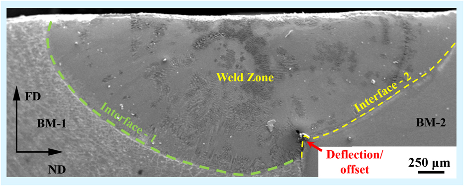
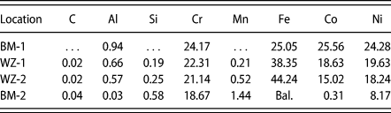
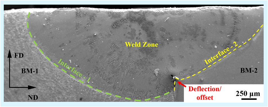
The transverse macrostructure of the dissimilar weldment (DW) made between Al0.1CoCrFeNi-HEA (BM-1) and AISI304 stainless steel (BM-2) is given in Fig. 1. The joint shows good weld bead geometry with full penetration and without any visible defects (such as porosity and cracking). Although the joint reveals proper fusion between the weld metal and the base metals, the weld bead shows slight deviation from the curvature of the fusion line (FL) toward BM-2, as indicated by the arrow shown in Fig. 1. Such asymmetry in the weldment shape has already been found in the dissimilar welding of 316 stainless steel with grade 2 titanium alloy due to the offset of laser beams [Reference Satoh, Yao and Qiu21]. The asymmetry in weld metal shape can also be influenced by the differences in melting point and physical and mechanical properties of alloys. It can be measured from Fig. 1 that the arc offset from BM-2 is around 400 μm. Hence, it corroborates with the deviation in the curvature of FL in the vicinity of BM-2. The chemical composition of the BMs and the weld was analyzed by the EDS area analysis technique, and results are provided in Table I.
Transverse macrostructure of the dissimilar weld showing the WZ and the interfaces.
Chemical composition (wt%) of base materials (BM-1—HEA and BM-2—AISI304) and WZ (WZ-1 toward HEA and WZ-2 toward AISI304) of the DW.

Phase analysis
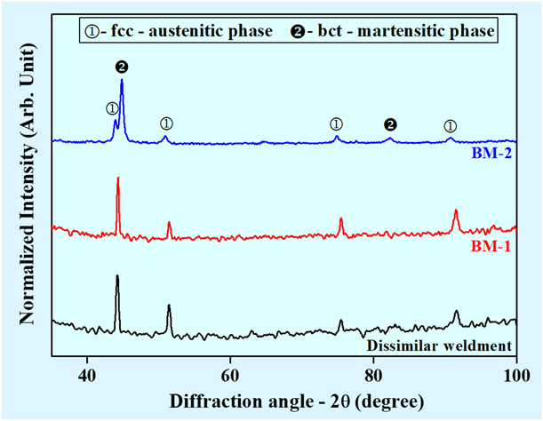
The X-ray diffraction (XRD) patterns of the base materials and the dissimilar weld zone (WZ) are shown in Fig. 2. As expected, BM-1 shows the diffraction peaks corresponding to only one phase, i.e., γ-fcc (from Al0.1CoCrFeNi-HEA) [Reference Yang, Tang, Xie, Carroll, Wang, Wang, Dahmen, Liaw and Zhang14, Reference Komarasamy, Kumar, Tang, Mishra and Liaw15, Reference Yu, Cheng, Zhang, Zhang, Jing, Ma, Liaw, Li and Liu16, Reference Kumar, Ying, Nie, Mishra, Tang, Liaw, Brennan, Doherty and Cho17, Reference Komarasamy, Alagarsamy and Mishra18], whereas the XRD pattern from BM-2 shows the presence of a dual phase, austenitic (γ-fcc structure) and martensitic phases (bct structure), as the AISI304 stainless steel is used in the as-received condition. This is consistent with the findings of Issartel et al., where the presence of such strain-induced martensite has been correlated as the cause of mechanical straining of the alloy [Reference Issartel, Buscail, Caudron, Cueff, Riffard, Perrier, Jacquet and Lambertin31]. Also, Jinlong et al. reported that the deformation of AISI304 at room temperature has resulted in the transformation of a fraction of austenite to martensite [Reference Jinlong, Hongyun and Tongxiang32].
XRD data showing patterns for the base metals (BM-1 and BM-2) and DW.
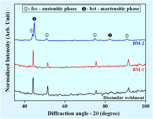
Although the formation of intermetallic compounds or microsegregation is expected during dissimilar welding, the XRD peaks of the WZ reveal only austenitic peaks with a minor peak shift. No additional peaks are observed, suggesting no new phase has formed during the welding process. From Table I, it can be seen that the fraction of Ni in the weld is higher than that in BM-2. The increased weight fraction of Ni in the WZ compared with that in BM-2 is a consequence of the fluid-dynamic mixing of Ni from BM-1 into the weld. Ni being an austenitic stabilizer may help in stabilizing the fcc-austenitic phase in the WZ [Reference Zhou, Chai, Yu, Ma and Wu25] without the formation of the brittle martensitic phase, even at rapid solidification of the weld (high cooling rate). In addition, the high solubility of alloying elements such as Al, Co, Cr, Fe, Mn, and Si in Ni retards the formation of intermetallic compounds and resulted in the supersaturated solid solution at the higher cooling rate [Reference Mortezaie and Shamanian22]. Hence, the solidification of weldment without the formation of brittle martensitic/intermetallic phases in dissimilar weld suggests the good compatibility between the HEA and AISI304 during this dissimilar welding process.
Microstructural and micro-texture analysis
Base metal microstructure
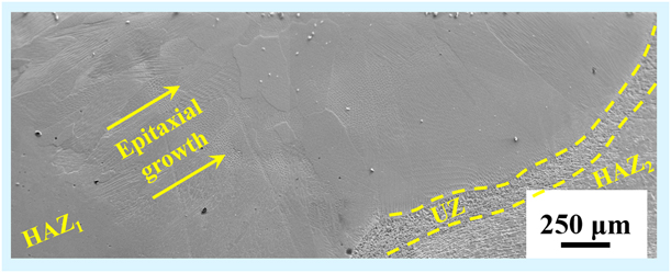
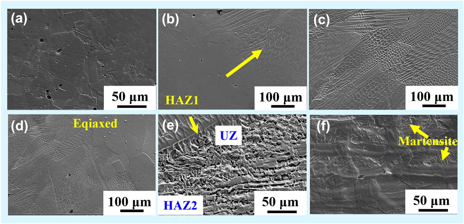
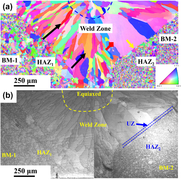
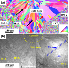
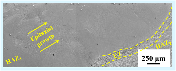
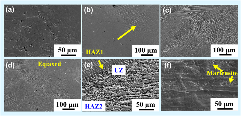
Figure 3 shows the overall scanning electron microscope (SEM) microstructure of the weldment which comprises the WZ, UZ, and the heat affected zone (HAZ). The overall microstructure of the WZ reveals the presence of the austenitic phase without any additional secondary phases. It may be interesting to observe that an epitaxial growth is observed in the WZ, especially along the HEA side. Figures 4(a)–4(f) show the SEM micrographs of the detailed view of the unaffected base metals (a) and (f), the interface along BM-1 (b) and BM-2 (e), and the WZ (c) and (d), respectively. Also, the electron backscattered diffraction (EBSD)–orientation imaging microscopy (OIM) images along with an inverse pole figure (IPF) inset, and corresponding image quality maps are given in Figs. 5(a) and 5(b). Both BM-1 and BM-2 show the presence of equiaxed austenitic grains with annealing twins (Figs. 4 and 5). Such occurrence of annealing twins is a common phenomenon in recrystallized fcc alloys having low stacking fault energy, such as HEA and AISI304 [Reference Komarasamy, Alagarsamy and Mishra18]. The average grain size of the BMs is 9 ± 2 µm and 8 ± 1 µm for BM-1 and BM-2, respectively. Recent studies on Al0.1CoCrFeNi-HEA have demonstrated the presence of coarse grains (in the range of millimeters) in both as-cast and annealed conditions [Reference Yang, Tang, Xie, Carroll, Wang, Wang, Dahmen, Liaw and Zhang14, Reference Komarasamy, Kumar, Tang, Mishra and Liaw15, Reference Yu, Cheng, Zhang, Zhang, Jing, Ma, Liaw, Li and Liu16, Reference Kumar, Ying, Nie, Mishra, Tang, Liaw, Brennan, Doherty and Cho17, Reference Komarasamy, Alagarsamy and Mishra18]. Generally, mechanical processing of materials (such as rolling and forging) can refine the grain size, with elongated grains in the rolling direction. Upon cryo-rolling of Al0.25CoCrFeNi-HEA, Hou et al. observed extensive fragmentation of grains into finer grains [Reference Hou, Zhang, Ma, Liaw, Zhang and Qiao33]. Li et al. also attained an average grain size of around 25 µm after forging [Reference Li and Zhang34]. Hence, in the present study, extensive mechanical processing by hot forging with 50% reduction in the thickness of HEA could have resulted in a very fine grain structure.
Scanning electron microscopy image of the dissimilar weld comprising different zones, namely, HAZ and unmixed zone (UZ).
SEM micrographs showing (a) base metal on the HEA side. (b) A detailed view of the interface along the HEA side, showing the HAZ and epitaxially growing (indicated by arrowhead) columnar grains. (c) A detailed view of the WZ showing columnar grains with cellular dendritic substructures. (d) WZ where the columnar grains transform to equiaxed grains at the weld center. (e) A detailed view of the interface along AISI304, indicating the presence of Type II grain boundary (indicated by arrowhead) and the presence of unmixed and HAZ. (f) View of the base metal along AISI304 showing a needle-like martensitic structure.
(a) Electron back scattered diffraction–OIM of the weldment showing the WZ, base metal (HEA and AISI304), and HAZs (1 and 2), with IPFs as inset. The arrow with a triangular arrowhead indicates epitaxial growth, with square arrowhead indicating Type I grain boundary, curved arrowhead indicating Type II boundary, and the dashed part at the top center indicating the transformation of columnar grains to equiaxed grains. (b) Corresponding secondary images.

The SEM micrograph [Fig. 4(f)] at higher magnification reveals the presence of fibrous banded structures with minor shear bands and needle-like martensite in the austenitic matrix. Such appearance of banded structures indicates that the as-received BM-2 is in a rolled condition. Banded structure in the austenitic structure was already reported in rolled AISI304L and AISI316 [Reference Chowdhury, Das and De35, Reference Lach, Nowak and Svyetlichnyy36]. The formation of a fibrous structure in austenitic stainless steel is attributed to the homogeneous deformation during the rolling, and the presence of a minor shear band indicates localized nonhomogeneous deformation. The needle-like martensite was also found as the result of heavy rolling deformation of austenitic stainless steel [Reference Abreu, Carvalho, Neto, Santos, Freire, Silva and Tavares37]. Mechanical processing of the AISI304 austenitic stainless steel may have refined the grains, with increased susceptibility to sensitization [Reference Jinlong, Hongyun and Tongxiang32].
Weld metal microstructure
The interface between BM-1 and the WZ (IF-1) as well as BM-2 and the WZ (IF-2) are shown in Figs. 4 and 5. IF-1 reveals the epitaxial growth of columnar grains from the partially melted grains of BM-1. Epitaxial growth is clearly demonstrated by the presence of similar orientation of grains at HAZ and weld metal at the solidification front adjacent to BM-1. Such kind of growth would occur when the chemical composition and crystal structures of the BM and the weld metal are matching [Reference Kou38]. In epitaxial growth, the atoms from the molten weld pool arrange themselves on to the preexisting lattice sites of the partially melted BM. Hence, the interface with epitaxial growth could possess better interfacial interaction and stronger metallurgical bonding.
On the contrary, IF-2 shows two different grain growth mechanisms. The non-epitaxial grain growth occurs adjacent to the top portion of IF-2, with a narrow UZ (thickness in the range of ∼25 μm) and epitaxial growth evolving in the lower region of the curvature bent in the IF-2 interface. The formation of the UZ becomes favorable when the melting range of the weld metal is similar or higher than that of the base metal. At that condition, only a fraction of the base metal could melt and resolidify without dilution [Reference Zhou, Chai, Yu, Ma and Wu25]. The composition of the UZ was found to be 71Fe–19.3Cr–8.4Ni by EDS analysis. The chemical composition of the UZ is nearly in the range of BM-2, whereas the composition in the WZ shows a reduced Fe content but higher Ni content, which clearly indicates that the UZ has not been diluted by the weld metal significantly.
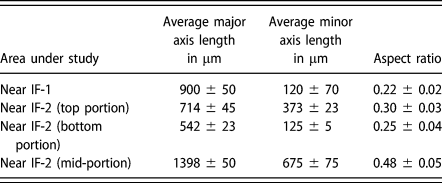
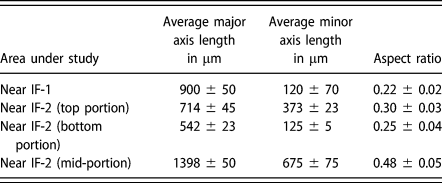
Although both the interfaces exhibit coarse grains in the WZ than the BMs, the microstructure of the weld metal along the IF-2 side is found to be coarser than that of the weld metal along the IF-1 side. Such relative increase in coarsening of grains in the weld metal along the IF-2 side could be attributed to non-epitaxial growth at the interface because such a growth links fusion zone grains with numerous grains of BMs. The variation in grain sizes along the two interfaces IF-1 and IF-2 could be attributed to the variation in temperature gradient as the consequence of the unsymmetric weld bead geometry. The grain size measurement has been carried out in the WZ near both IF-1 and IF-2. To simplify the quantification process, the columnar grains were assumed to have a roughly elliptical structure, and its minor and major axis lengths along with the aspect ratio were measured and their average values tabulated in Table II. The mid-portion of the WZ near the IF-2 interface has shown nearly double the grain size than that in other regions of the WZ. This indicates that the grain at this region orients/grows more favorably along the temperature gradient. Favorable alignment of the grain at this region thus increases the growth rate along the favorable direction and lateral direction by the competitive growth mechanism phenomenon [Reference Kou38]. It can be observed from Figs. 5(a) and 5(b) that the columnar grains transform to equiaxed grains as they approach the top center of the weld. The columnar grains in the WZ comprise a cellular substructure, as shown in Figs. 3 and 4(c). The equiaxed grains have an average size of ∼64 ± 5 µm.
Columnar grain size analysis in the WZ.
The grain size in the HAZ on the BM-1 side (HAZ1) and BM-2 side (HAZ2) was measured to be 13.6 ± 3 µm and 10 ± 2 µm, respectively. Microstructures along both HAZs show the presence of considerable amount of twins, with marginal grain coarsening compared with the BMs. Normally, grain coarsening can occur when the base metal is exposed to a higher temperature for a longer duration (i.e., having lower thermal conductivity) or when the base metal lacks in secondary phases to pin growth. The higher lattice distortion with subsequent lower diffusion in the HEA reduces the thermal conductivity [Reference Guo5] of the material than that of conventional alloys such as AISI304. As BM-1 is a single fcc structure without any second phase, it has resulted in significant grain coarsening at HAZ1 than that observed at HAZ2, which suggests that the grain coarsening criteria in HAZ1 are due to the lower thermal conductivity and lack of secondary phases. Because BM-2 exhibits a considerable fraction of strain-induced martensite in addition to an fcc austenitic structure [from XRD data in Figs. 2 and 4(f)], the grain coarsening in its HAZ is rather restricted.
The columnar grain formation in the fusion zone is similar to the solidification behavior of general fcc alloys. These columnar grains are formed by a competitive growth mechanism of dendrites, i.e., the grains at the HAZ that aligned closely to the direction of the temperature gradient can compete for the growth compared with other grains with misfit [Reference Eghlimi, Shamanian, Eskandarian, Zabolian and Szpunar20, Reference Wu, David, Leonard, Feng and Bei29]. Grains at the center of the WZ become finer and equiaxed than grains near the fusion boundary, which are fairly coarser and elongated than the BMs. The presence of fine equiaxed grains in the center of the WZ is attributed to the constitutional supercooling. Constitutional supercooling can be enhanced by the reduction in the ratio of the temperature gradient (G) to the growth rate (R) of weldments during solidification. Assuming the constant “G” during welding, it was proposed that the “R” is maximum at the weld center and is minimum at the periphery of the weld [Reference Eghlimi, Shamanian, Eskandarian, Zabolian and Szpunar20, Reference Mortezaie and Shamanian22]. It was also found that the heat input by the weld power source is directly proportional to constitutional supercooling [Reference Eghlimi, Shamanian, Eskandarian, Zabolian and Szpunar20]. Because GTAW is well known for high heat input, it promotes a high degree of constitutional supercooling and, hence, promotes the formation of such finer equiaxed dendrites at the weld center. The phenomenon of grain coarsening in the WZ than BMs was also observed in electron beam welding of CoCrFeMnNi HEAs [Reference Wu, David, Leonard, Feng and Bei29], TIG welding of GH625 superalloys [Reference Gu, Tao, Wei and Liu39], and Al–Zn–Mg–Cu alloy welded with TIG and laser welding [Reference Zhang, Li, Nie, Huang and Niu40]. Such coarsening of grains in the WZ could result in deterioration of its mechanical property and reduces its resistance to plastic deformation [Reference Wu, David, Leonard, Feng and Bei29].
Micro-texture evolution by welding and grain boundary distribution
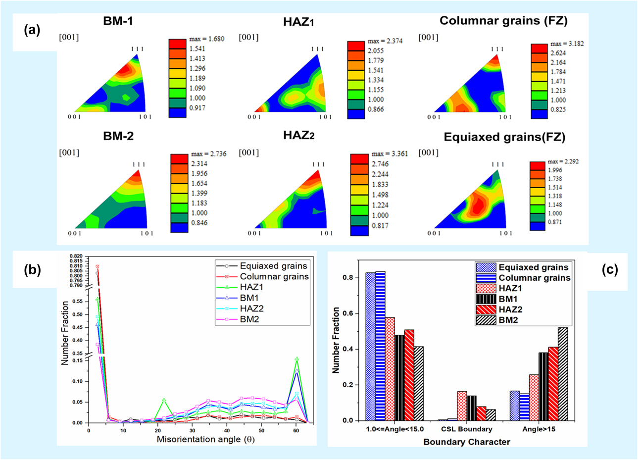
Figures 6(a)–6(c) show the IPF and statistical data of distribution of misorientation angle and fraction of different kinds of grain boundaries extracted from the EBSD data at different regions, viz., BM-1, BM-2, HAZ1, HAZ2, columnar grains below the curvature at IF-2 (where columnar to equiaxed transition has not occurred), and equiaxed grains at the top center of the weld in dissimilar weld joint. The BM-1 shows the dominant orientation toward the 〈111〉//WD direction and weak texture along 〈100〉//WD, whereas the BM-2 grains show orientation predominantly in the 〈111〉//WD. The HAZ regions affected by the weld heating cycle shows transformation of crystal orientations as follows: the grains at HAZ1 orient themselves toward the 〈100〉//WD direction with weak texture orientation between 〈321〉//WD and 〈311〉//WD directions, whereas the grains at HAZ2 remain oriented at 〈111〉//WD as in BM-2 with meager texture development toward the 〈100〉//WD direction. It can be seen from Fig. 5 that the epitaxially grown columnar grains at IF-1 are textured toward the easy growth 〈100〉//WD direction, whereas the columnar grains in IF-2 show growth orientation deviated from the easy growth 〈100〉//WD direction. The equiaxed grains in the weld fusion zone that underwent hydrostatic mixing of BMs show 〈531〉, 〈211〉, and 〈331〉//WD orientation at the top center of the weld. The columnar grains below the curvature of the weld reveal predominantly 〈310〉 and 〈111〉//WD orientation.
(a) IPF (b) misorientation angle distribution and (c) grain boundary character distribution at different regions in the dissimilar weld joint.
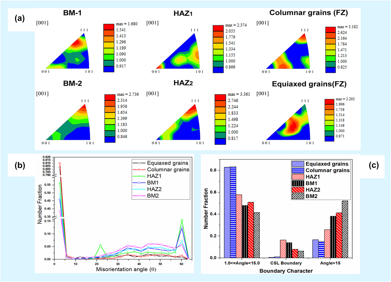
As welding proceeds, the grains in HAZ orient themselves toward the preferential growth 〈001〉 direction. As can be seen from Fig. 6, the grains at HAZ1 orient easily and attain texture orientation along the 〈001〉 direction, whereas the grains at HAZ2 never attain the preferential growth direction with the available heat input and exposure time during welding. Easier transformation of grain orientation in HAZ1 could be attributed to the single-phase characteristics of BM-1, whereas in case of BM-2 the presence of a small amount of strain-induced martensite (bcc) restricts the grain reorientation during exposure to a higher temperature.
During solidification of the molten weld pool, favorably oriented grains of HAZ1 wet the molten weld pool completely at the solidification front. Hence, the atoms from the weld pool arrange themselves in preexisting lattice sites of partially melted HAZ1 grains and develop texture preferentially along the 〈100〉//WD direction. The orientation of epitaxially grown columnar grains in the IF-1 side depends both on the thermal gradient from the base metal to the weld center and on the crystallographic effect of HAZ1. Hence, the columnar grains adjacent to FL obviously orient themselves to the easy growth direction of fcc metals. As reported earlier, the competitive growth phenomenon promotes the growth of favorably oriented grains and suppresses the growth of unfavorably oriented grains [Reference Wu, David, Leonard, Feng and Bei29]. The initially growing grains that favorably orient in a bowl-shaped weld pool may not be favorably oriented for the whole solidification process. Hence, it changes from favorable to unfavorable orientation, and vice versa. The grains optimally aligned to the easy growth direction form elongated grains, whereas the others end up solidifying with a relatively finer size [Figs. 5(a) and 5(b)].
However, the partially melted grains in HAZ2 solidify without diluting with the weld pool and form a narrow UZ. Supercooling of the weld metal pool by heterogeneous nucleation at the UZ initiates the growth of coarse columnar grains adjacent to the UZ. As the columnar grains in IF-2 are not growing epitaxially, they find their favorable growth direction at the initial growth stage itself. These columnar grains could have aligned to the easy growth direction for more duration than the epitaxially grown columnar grains at the IF1 interface. Hence, longer growth duration of grains with higher lateral growth makes these grains coarser. In case of equiaxed grains at the center of the weld, the orientation is influenced by the weld torch movement, which results in their orientation in a completely different manner.
The grain boundaries present in the weldment have been divided into three major categories depending on the misorientation angle. The grain boundaries that exhibit 0–5° misorientation angle is low-angle grain boundary (LAGB) generally found in substructures. The grain boundaries with the misorientation angle between 5° and 15° and more than 15° are categorized as medium angle (MAGB) and high-angle grain boundaries (HAGB), respectively. Figure 6(b) shows that the WZ has more fractions of HAGBs than other regions. These HAGBs are further subcategorized based on the coincident site lattice (CSL) boundary as special twin boundary and random boundaries. It was proposed that the occurrence of misorientation angle ∼60° indicates a twin boundary. The grain boundaries with Σ (the parameter to indicate geometrical matching) value less than 29 are special boundaries, whereas others are random boundaries. BM-1 and BM-2 reveal significant HAGB distribution, whereas the grains in the weld fusion zone show very less fraction of HAGB because the existence of twin boundary has a major influence on the mechanical property as it acts as a barrier for plastic deformation. It is important to confirm the occurrence of such special twin boundaries, i.e., CSL boundary distribution. Hence, the study of the CSL boundary distribution in BMs and the WZ of weldment has been done as follows. Both BMs show very less fraction of random CSL boundaries. The proportion of CSL boundary corresponding to the primary twin is higher in the order of BM-1 > BM-2. On the other hand, it can be seen that the grain boundaries in the weld fusion zone comprise random boundaries with very less fraction of CSL twin boundaries [Fig. 6(c)]. Gu et al. observed high- and low-angle random boundaries in the fusion zone during the welding of superalloys with austenitic twin boundaries [Reference Gu, Tao, Wei and Liu39]. The present work also shows such high- and low-angle random boundary distribution. The reduction in the fraction of CSL boundaries and continuous random boundary networks was already reported to reduce the mechanical properties [Reference Tokita, Kokawa, Sato and Fujii41]. Hence, in the present case, the welding process led to reduced CSL boundary and deterioration of their mechanical properties is expected.
Mechanical properties
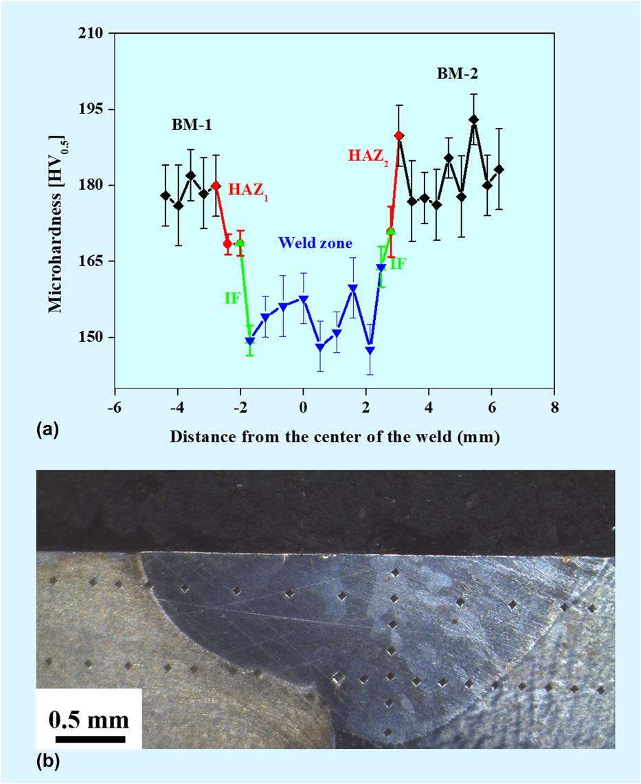
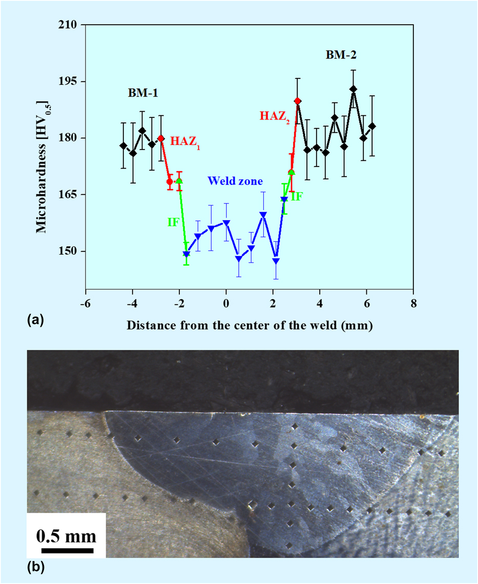
The microhardness survey across the weldment and corresponding weldment macrostructure with indents are given in Figs. 7(a) and 7(b). BM-1 and BM-2 show the microhardness of ∼178 ± 10 HV0.5 and 180 ± 6 HV0.5, respectively. Recent reports on HEAs show that friction stir welding of coarse grained and hot-isostatically pressed alloys have resulted in grain refinement assisted hardness improvement from 140 HV0.5 to 200 HV0.5 [Reference Komarasamy, Kumar, Tang, Mishra and Liaw15]. Hence, it is obvious that the base metal with grain refinement due to forging could result in increased hardness (178 ± 10 HV0.5) than that in the as-cast condition. In the case of BM-2, it shows higher hardness (180 ± 6 HV0.5) than commercially available 304SS (170 HV) [Reference Kumar, Mukherjee and Bandyopadhyay19]. This marginal enhancement could be attributed to the formation of martensite and dislocation pile-ups in the as-received rolled condition. It is clear from the plot that the hardness distribution in the WZ is lower than the hardness of the base materials. This could be attributed to the evolution of the coarse columnar grains in the weld and vanishing of twin boundaries during welding. Both the HAZs (HAZ1 and HAZ2) show slightly lower hardness than BM-1 and BM-2, respectively. This marginal drop in hardness may be attributed to the coarsening of grains in the HAZs.
(a) Microhardness distribution across the dissimilar weld and (b) corresponding optical microscopy image showing the indents.
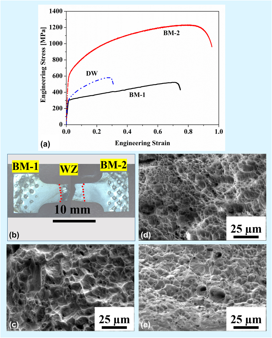
The room temperature tensile stress–strain plot for BM-1, BM-2, and DW is given in Fig. 8(a). BM-1 shows an ultimate tensile strength (UTS) of 327 ± 15 MPa with yield strength (YS) and ductility of 148 ± 10 MPa and 58 ± 4%, respectively. This is consistent with the work of Komarasamy et al., where they found the YS, UTS, and elongation of coarse-grained Al0.1CoCrFeNi-HEA (range of few millimeters) to be around 160 MPa, 390 MPa, and 45%, respectively [Reference Komarasamy, Kumar, Tang, Mishra and Liaw15]. BM-2 has shown a YS of 620 ± 20 MPa, an UTS of 1223 ± 25 MPa, and an elongation of 95 ± 7%. The results are consistent with that of cold-rolled AISI304 [Reference Milad, Zreiba, Elhalouani and Baradai42]. The DW (comprising BMs, HAZ, and WZ) shows a YS of 265 ± 15 MPa, an UTS of 590 ± 20 MPa, and a ductility of 38 ± 5%. The failure of DW has occurred at the WZ [Fig. 8(b)], attributable to the lower hardness of the weld. Interestingly, the property of the DW is between the two base materials with expense of the ductility.
(a) Room temperature stress–strain curve of base metals and weldment. (b) The macrograph of the weldment showing the fracture position after tensile test and fractographs of (c) BM-1, (d) BM-2, and (e) DW.
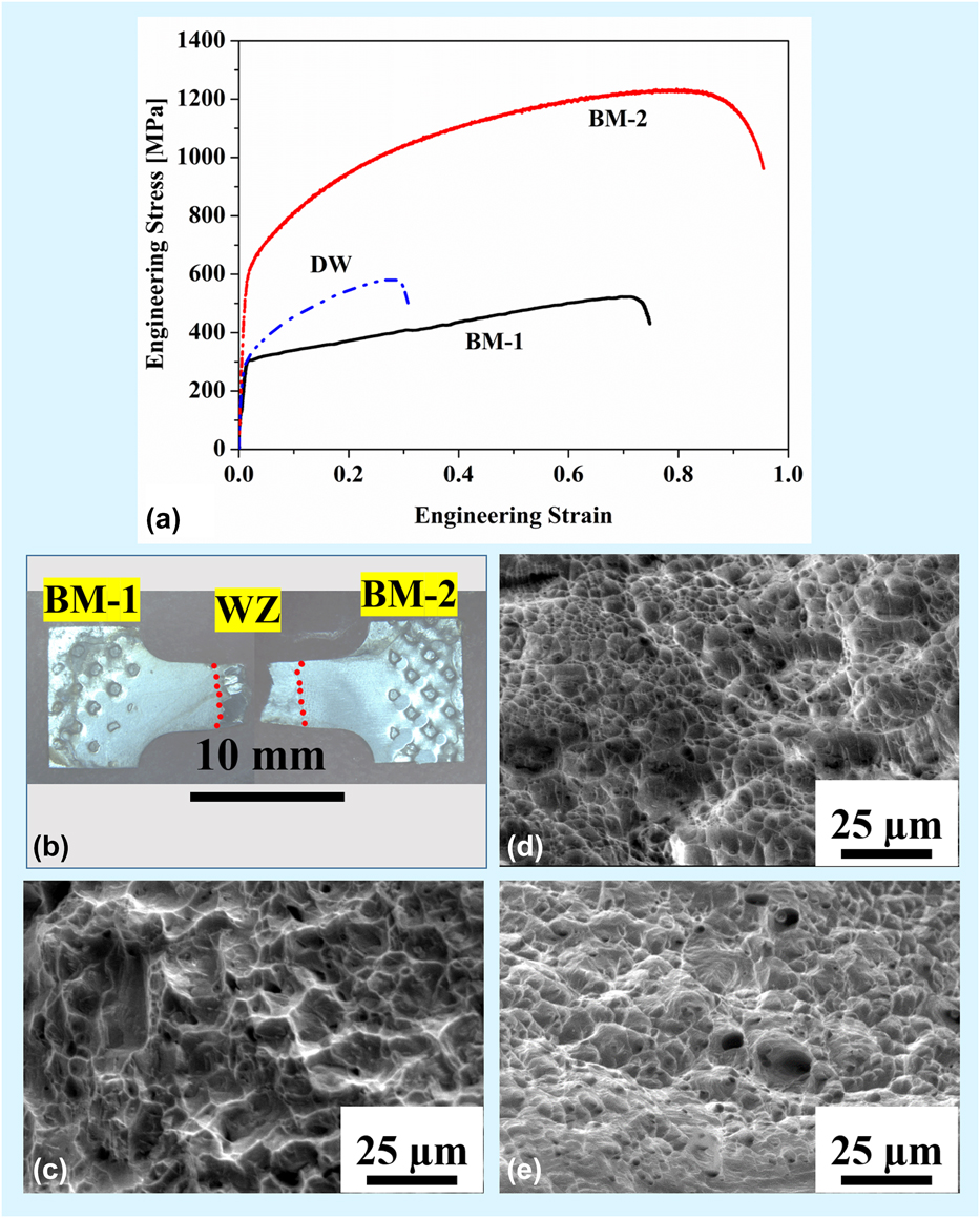
The gauge length of the DW that underwent the deformation comprises BM-1, HAZ1, WZ, UZ, and HAZ2, and BM-2 showed higher tensile strength than BM-1; however, the WZ showed lower hardness than BM-1. This could be attributed to the occurrence of the complicated plastic deformation in the weldment with heterogeneous microstructure (varying microstructure at different regions with varying fractions of the LAGB, MAGB, HAGB, and CSL boundaries). Because the regions with different microstructures (e.g., equiaxed and columnar grain structures) and different fractions of the grain boundary distributions could have different deformation resistance, tensile test result of the DW weldment could be the result of the average response of each zone toward the adjacent zones. Such complicated tensile deformation has already been noticed in similar [Reference Jo, J Kim, Kang, Madakashira, Park, Suh, Kim, Hong and Han43] and dissimilar welds [Reference Mortezaie and Shamanian22]. It was reported that the cracking susceptibility of the base metal with isotropic equiaxed grains is less than that of the weld metal with the columnar grains due to the complicated crack propagation path in the equiaxed grains [Reference Zhu, Ng, Qiao, Liaw, Chen, Nai, Wei and Bi26]. In addition to this, the residual stresses induced in the weld during solidification of the weld joins together for the reduction of the ductility. Overall, the weldment shows higher strength than one of the base metals (HEAs); hence, this transition joint could meet the requirements of the structural application.
The fracture surfaces of BMs and the weld are shown in Figs. 8(c)–8(e). The fracture surface shows predominantly ductile mode of failure. BM-2 exhibits fine dimples, which obviously reveal the higher strength and ductility of the material, whereas BM-1 shows intergranular fracture with relatively coarse dimples. The fracture surface of the WZ shows a dimpled morphology with some void formation. The presence of such voids hampers both the strength and ductility of the DW. Nevertheless, the properties are better than those of the HEA material, and hence can be used for structural applications.
Conclusion
Dissimilar transition joint was produced between Al0.1CoCrFeNi-HEA and AISI304 austenitic stainless steel with tungsten inert gas welding. The microstructural variations resulting from the welding process were carefully analyzed and are correlated with their mechanical properties. Important conclusions of the present study are illustrated as follows:
(1) Dissimilar joint was obtained without any major defects such as porosity and cracks.
(2) The WZ along the HEA shows the presence of epitaxial columnar dendritic grains. On the other hand, the WZ along the AISI304 steel side exhibits non-epitaxial growth of grains. However, the weld center reveals the presence of fine and equiaxed dendritic grains.
(3) EBSD of the WZ reveals a random orientation of grains and reduction in the fraction of CSL boundaries and continuous random boundary networks.
(4) The dissimilar joint show superior strength (YS ∼ 265 MPa and UTS ∼ 590 MPa) than one of the base materials, i.e., Al0.1CoCrFeNi-HEA (YS ∼ 148 MPa and UTS ∼ 327 MPa), indicating that the joint efficiency should be better than that of the base metal along the HEA side. This suggests that the weldment meets the requirements of room temperature structural applications.
Materials and methods
Base material preparation
Al0.1CoCrFeNi-HEA and AISI304 austenitic stainless steel having a thickness of 1.5 mm each were selected as the base materials. Al0.1CoCrFeNi-HEA was prepared by using a vacuum arc melting facility specially made by Mansha Vacuum Equipments Pvt. Ltd., Bangalore, India. Each element (Al, Co, Cr, Fe, and Ni) having purity more than 99.9% was used for the alloy preparation. Alloys were remelted for four times to ensure chemical homogeneity. The button type samples from arc melting were drop-forged to a thickness of 2.5 mm and subsequently reduced to 1.5 mm by surface grinding. The as-received AISI304 was cut into the following dimension: 250 × 25 × 1.5 mm.
Dissimilar welding
Autogenous dissimilar butt welding between Al0.1CoCrFeNi-HEA and AISI304 austenitic stainless steel was performed using a mechanized Lincoln V205-T AC/DC GTA welding machine. The welding was carried out with varying traverse speeds of welding torch (50 mm/min, 75 mm/min, 100 mm/min, 125 mm/min, and 150 mm/min). The welding parameters, 10–11 V voltage, current of 50 A, and speed of 100 mm/min, resulted in the weld with full depth of penetration, and the resultant heat input for these parameters is calculated as 180 J/mm.
Metallurgical characterization and mechanical testing
The macrographs of the cross-section of the joints were recorded using a HITACHI S-3000H SEM, Mannheim, Germany. The phases present in the BMs and dissimilar weld joint were identified from the X-ray diffraction (XRD) patterns recorded from UltimaIII, Rigaku, Neu-Isenburg, Germany X-ray diffractometer operated at 40 kV and 30 mA with Cu Kα radiation between 35° and 100° (2θ) with a step size of 0.05°. Grain orientation and micro-texture of the weldment (traverse direction) were analyzed by using the EBSD technique in FEI Quanta—3D FEG—SEM (Field emission gun—scanning electron microscope) equipped with a TSL-OIM EBSD unit. The reference coordinates used for scanning are denoted as normal direction (ND), filling direction (FD), and welding direction (WD), as mentioned in Fig. 1. Elemental distribution and homogeneities near the FLs of the DW were studied by energy-dispersive spectroscopy (both line and area scanning were performed). The grain sizes were measured using an average intercept method using ImageJ software, Wisconsin. Microhardness survey across the weld material was carried out under an applied load of 500 g with a dwell time of 10 s. Micro-tensile samples were extracted within the weldment with a thickness of 0.5 mm and gauge length of 6 mm. Tensile tests were carried out for the BMs and the weldment at a strain rate of 2.5 × 10⁻³/s in a Instron 5582 tensile testing unit (Darmstadt, Germany). Fractured tensile specimens were examined under the SEM to analyze the fracture mode.
Acknowledgments
The authors would like to thank Professor Indradev Samajdar, Department of Metallurgical Engineering and Materials Science, IIT-Bombay, India, for providing electron backscattered diffraction (EBSD).