1. INTRODUCTION
A ballistic missile is a type of long-range weapon, whose accuracy depends on its navigation, guidance and control system. For several decades, the Inertial Navigation System (INS) has been the most popular navigation mode. However, INS accuracy will degrade over time due to gyro drift and accelerometer bias. To improve accuracy significantly will generally lead to a high cost navigation system. Hence INS cannot easily satisfy the requirement for higher accuracy. With the development of navigation technology, some integrated navigation techniques, which can improve navigation accuracy significantly as well as reduce cost, are being implemented (Fall et al., Reference Fall, Dipipi, Slivinsky and Paul2008).
The Global Positioning System (GPS) was first applied to improve the navigation accuracy of ballistic missiles as a high-accuracy positioning method (Ali and Fang, Reference Ali and Fang2009; Wang and Wang, Reference Wang and Wang2012). Although GPS can improve the navigation accuracy of INS, its vulnerability to jamming and the hostile environment makes it a poor choice. An INS/GPS integrated autonomous navigation scheme is not practical in wartime. A Celestial Navigation System (CNS) can be used to correct the INS's error (Hong et al., Reference Hong, Liu, Chen and Deng2010) because of resistance to interference, high accuracy and autonomy. Therefore, a new autonomous navigation model composed of INS and CNS has been established. Recently, with the geomagnetic model becoming more and more detailed, integrated autonomous navigation based on an INS and geomagnetic navigation system is being widely used. This navigation scheme uses geomagnetic information to estimate the position and attitude of the missile (Nordlund and Gustafsson, Reference Nordlund and Gustafsson2009; Guo et al., Reference Guo, Cai and Hu2014). The optimal estimation of navigation information can be obtained with a mixed Kalman filter by using the difference between magnetometer measured values and the geomagnetic model (Li et al., Reference Li, Wang, Jin, Qin, Li and Gao2015). In addition, when the missile leaves Earth's atmosphere, starlight can be used for the determination of the Earth horizon, which can be measured according to the relationship between stellar refraction and atmospheric density (Qian et al., Reference Qian, Sun, Cai and Peng2013; Ning et al., Reference Ning, Wang, Bai and Fang2012). Furthermore, the high precision of star sensors makes it possible to correct the error of navigation, so that the accuracy of navigation can be improved significantly by only using starlight as measurement information directly (Ning and Fang, Reference Ning and Fang2009; Wei et al., Reference Wei, Li, Li and Jiang2014). Wang and Zhang (Reference Wang and Zhang2008) improved the accuracy of integrated navigation by combining direct sensing horizon and indirect sensing horizon considering the low precision of the Earth sensor.
This paper improves the accuracy of SINS by using an integrated CNS made up of star sensor and Earth sensor. Since a star sensor is a type of high precision measuring equipment, the accuracy of the integrated navigation system depends on the precision of the Earth sensor. The Earth sensor obtains the attitude of the missile or the geocentric vector by sensing the atmospheric infrared radiance, so that the oblateness and infrared radiance of the Earth have a great influence on the measurement results of the Earth sensor. Compensation for the Earth oblateness has been researched intensively (Tekawy et al., Reference Tekawy, Wang and Gray1996). Generally, we can make first order correction and compensation, using numerical methods, on the scanning angle obtained by a horizon sensor (Li, Reference Li1999) or compensate the attitude angle by figuring out the error model in analytical form via analysing the oblateness function of the Earth (Zhou and Qian, Reference Zhou and Qian2003). As for compensating the asymmetry of Earth infrared radiance, the present research is limited. It is difficult to find a simple analytical method to compensate the asymmetry of Earth infrared radiance because of the influence of different latitude, different seasons and atmospheric density. Alex and Shrivastava (Reference Alex and Shrivastava1989) found the relationship between scanning voltage and attitude error according to the transfer function of radiance and scanning voltage. Then, the compensation method on attitude error is established by fitting the relationship as a quadratic function. Ward (Reference Ward1982) establishes the function between atmospheric radiance and effective horizon height by using related atmospheric software, considering that the measurement of the Earth sensor is closely related to the profile of radiance. Furthermore, Gontin and Ward (Reference Gontin and Ward1987) derived an error function of effective horizon height and makes compensation on the measurement of the static and scanning sensors respectively.
The above references pay little attention to the theoretical analysis for correction of geocentric vectors, although they make some compensation on the attitude of the vehicle. This paper analyses the navigation error caused by the asymmetry of Earth infrared radiance. According to the spherical geometry, the correction relationship between effective horizon height and measurement value is derived. The output of the Earth sensor can be compensated by the proposed correction function and the geocentric vector will be corrected. A new integrated navigation scheme based on a Strapdown Inertial Navigation System (SINS), star sensor and Earth sensor is proposed and the navigation information is estimated by using the batch processing least square method. Simulation results show its feasibility and effectiveness.
2. ERROR MODEL OF EARTH INFRARED RADIANCE
2.1. Determination of Geocentric Vector
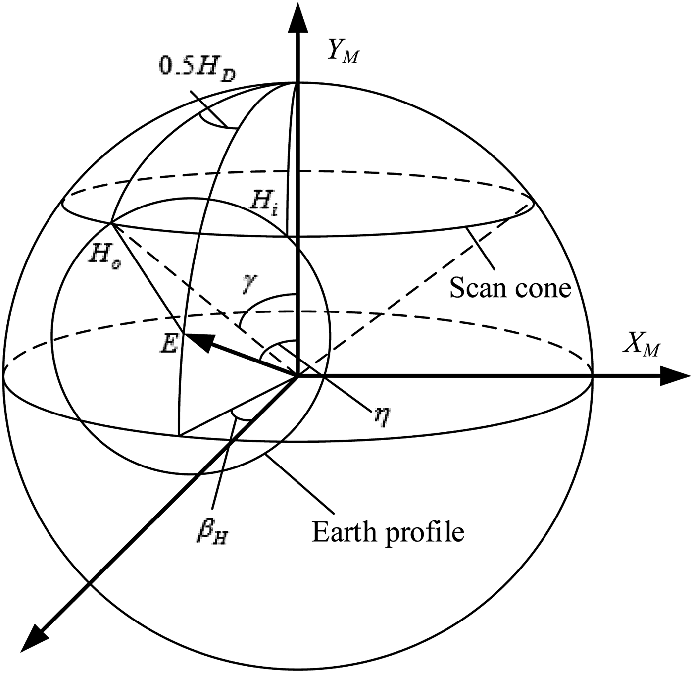
When the scanning Earth sensor works over a certain period, the scanning field will be a cone with a semi-cone angle γ. As shown in Figure 1, H i and H o represent space-to-Earth point and Earth-to-space point respectively in the measurement coordinate system O-X M YMZM. E is the centre of the Earth. η represents the angle between scan axis O M Y M and Earth local vertical line.
Geometrical relationship of Earth sensor scanning.
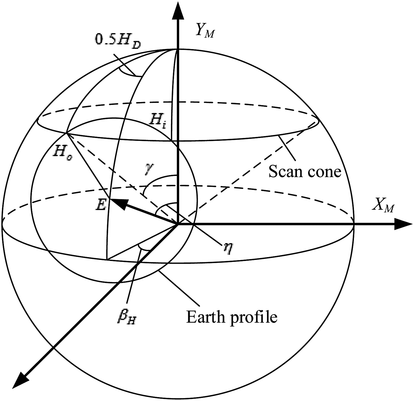
Assuming that the time of scan-in is t i , the time of scan-out is t o and the time of reference point is t s . The chord width of scan-in point to reference point and the whole chord length H D are as follows, respectively.
 $$\eqalign{& {H_S} = \displaystyle{{{t_s} - {t_i}} \over {{T_S}}} \times 360^{\circ} \cr & {H_D} = \displaystyle{{{t_o} - {t_i}} \over {{T_S}}} \times 360^{\circ}}$$
where T S represents the period of scanning. Define the deviation of the attitude angle as:
 $${\beta _H} = 0.5\,{H_D} - {H_S}$$
According to the time of scan-in and scan-out as well as spherical triangle cosine theorem, we have:
 $$\cos \rho = \cos \gamma \cos \eta + \sin \gamma \sin \eta \cos \displaystyle{{{H_D}} \over 2}$$
where:
 $$\rho = \arcsin \displaystyle{{{R_e} + {h_{CO2}}} \over R}$$
h CO2 represents the thickness of Earth carbon absorption layer.
According to Equations (2) and (3) we can obtain the values of β H and η. Then, we can obtain components of the geocentric vector in the measurement coordinate system as follows:
 $${{\bi E}_m} = \left[ {\matrix{ { - \sin {\beta _H}\sin \eta} \cr {\cos \eta} \cr {\cos {\beta _H}\sin \eta} \cr}} \right]$$
In this way, the geocentric vector can be obtained according to the measurement information of Earth sensor at every sampling time.
2.2. Error Model of Infrared Radiance
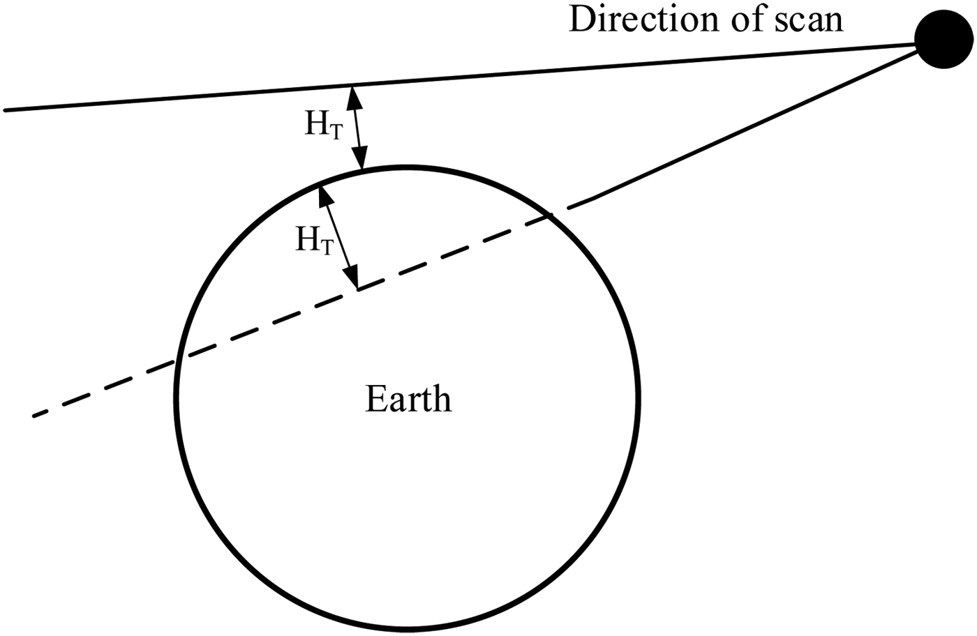
An Earth infrared sensor views the Earth in the 14–16 micrometre CO2 absorption band. The sensor will detect a perfect sphere if the infrared radiance of the Earth is symmetrical. However, since the infrared radiance changes as a function of latitude and season, the infrared profile of the Earth detected by the sensor is not symmetrical as a matter of fact. As shown in Figure 2, the height of Earth horizon H T is related to the asymmetry of infrared radiance, and it is the variation of H T that leads to the measurement error of the Earth sensor.
Definition of horizon height.
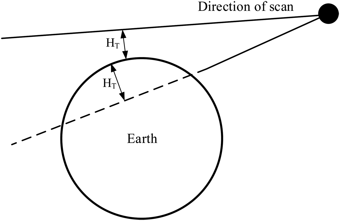
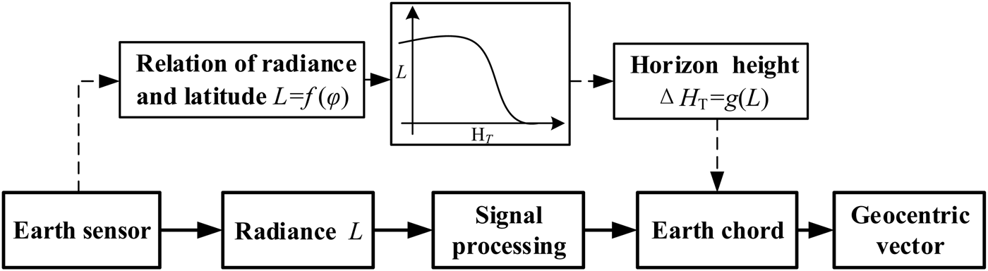
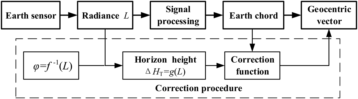
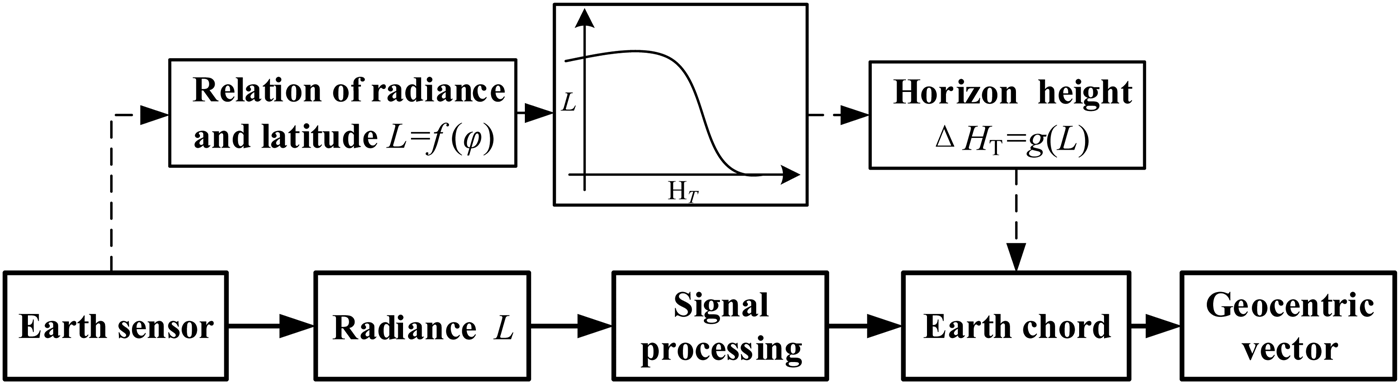
Figure 3 shows the working process of the Earth sensor, and the dotted lines show how measurement error of the Earth sensor occurs. It is obvious that the relationships between atmosphere radiance and latitude as well as season, height of Earth horizon and radiance should be found to establish the error model of infrared radiance.
Block diagram of Earth sensor.
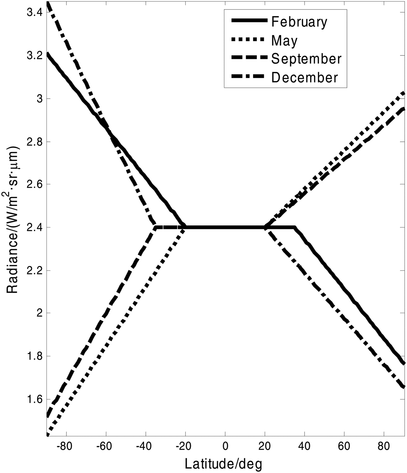
In order to establish the quantitative relationship between radiance and latitude as well as season, we use the Earth infrared radiance model obtained from French company SODERN. Figure 4 shows the relation curves of the Earth infrared radiance as a function of latitude in different seasons.
Radiance change with latitude and seasons.
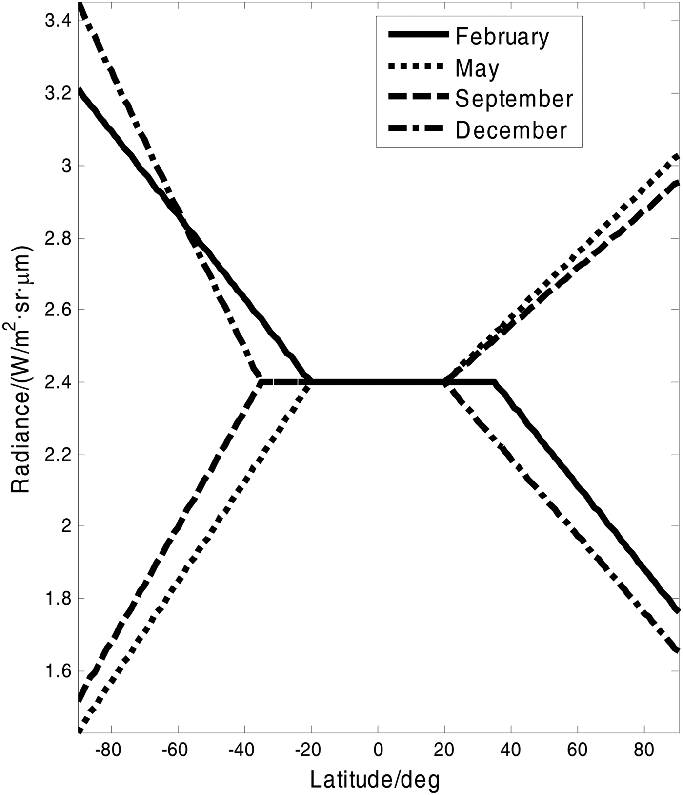
From Figure 4, we can see that the radiance is decreasing in February and December in the Northern Hemisphere, and is increasing in May and September with latitude increasing. In the Southern Hemisphere, the case is contrary. The radiance has little fluctuation from 20°S to 20°N.
Following this, we need to establish the quantitative relationship between radiance and height of the Earth horizon. First, we obtain the relationship between height of Earth horizon and radiance at different latitudes, utilising a software developed by NASA called CORPS (Comprehensive Radiance Profile Synthesizer), which can generate the Earth radiance profile based on atmospheric temperature and pressure (Ward, Reference Ward1982). Then, according to the calculated results, we approximate the relationship between radiance brightness and height of Earth horizon with a linear function below:
 $${H_T}(L) = \left\{ {\matrix{ {0.7(L - 1.5) + 35.8} \hfill & {L \lt 2.5} \hfill \cr {14.75(L - 1.5) + 36.6} \hfill & {2.5 \lt L \lt 2.9} \hfill \cr {1.36(L - 2.9) + 42.5} \hfill & {2.9 \lt L \lt 4.0} \hfill \cr}} \right.$$
From the function, we can derive an error function ΔH T = h CO2 − H T (L), which is the difference between standard atmospheric thickness and effective horizon height. This function is useful in compensation which will be discussed later.
3. COMPENSATION OF EARTH SENSOR INFRARED ERROR
Figure 5 shows the compensation process of infrared radiance error. The output value of the Earth sensor can be corrected, as long as the relationship between horizon height and t i , to is obtained.
Block diagram of correction for radiance error.
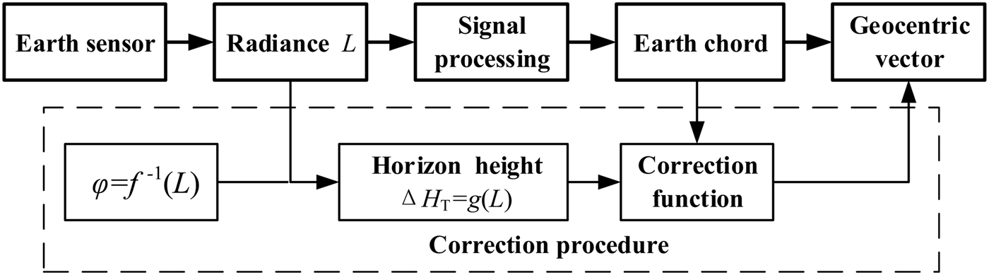
In order to establish the correction function, we assume that the infrared radiance is not uniform at space-to-Earth point, the angle of sight at this point is:
 $${\tilde \rho _i} = {\rm sin}{^{ - 1}}\displaystyle{{{R_e} + {{\tilde H}_{Ti}}} \over R}$$
where R represents the distance from missile to centre of the Earth; R
e
represents the radius of the Earth;
 ${\tilde H_{Ti}}$
is the horizon height at space-to-Earth point. According to the relationship given by Equation (6), we can calculate the horizon height error ΔH
Ti
(L
i
) at the space-to-Earth point. Therefore, the angle of sight at space-to-Earth point after correction is:
 $${\tilde \rho _i} = {\rm sin}{^{ - 1}}\displaystyle{{{R_e} + {{\tilde H}_{Ti}} + \Delta {H_{Ti}}} \over R}$$
According to the cosine theorem of a spherical triangle, the chord width H ie from H i to E can be calculated after correction:
 $${H_{ie}} = {\cos ^{ - 1}}\displaystyle{{\cos {{\tilde \rho} _i} - \cos \gamma \cos \eta} \over {\sin \gamma \sin \eta}}$$
Similarly, when the infrared radiance is not uniform at the Earth-to-space point, the chord width H oe from E to H o can be calculated after correction:
 $${H_{oe}} = {\cos ^{ - 1}}\displaystyle{{\cos {{\tilde \rho} _o} - \cos \gamma \cos \eta} \over {\sin \gamma \sin \eta}}$$
The whole chord width of the Earth, as scanned by the sensor, is:
 $${\tilde H_D} = {H_{oe}} + {H_{ie}}$$
The chord width from space-to-Earth point to the reference point is:
 $${\tilde H_S} = {H_{ie}} - {\beta _H}$$
Finally, according to Equations (9) to (12), we can derive the relationship between chord width and horizon height:
 $$\eqalign{& {{\tilde H}_D} = {\Phi _1}(\Delta {{\rm H}_{Ti}},\Delta {H_{To}}) \cr & {{\tilde H}_S} = {\Phi _2}(\Delta {{\rm H}_{Ti}})}$$
The navigation accuracy can be improved by using the corrected value to calculate the geocentric vector. As can be seen from Equation (8), the error of angle of sight can be reduced with the precision of Earth sensor being invariable when increasing orbital altitude, so that we can reduce the sensor's output error.
4. AUTONOMOUS NAVIGATION CONSIDERING THE ASYMMETRY OF ATMOSPHERIC RADIANCE.
4.1. Navigation Principle
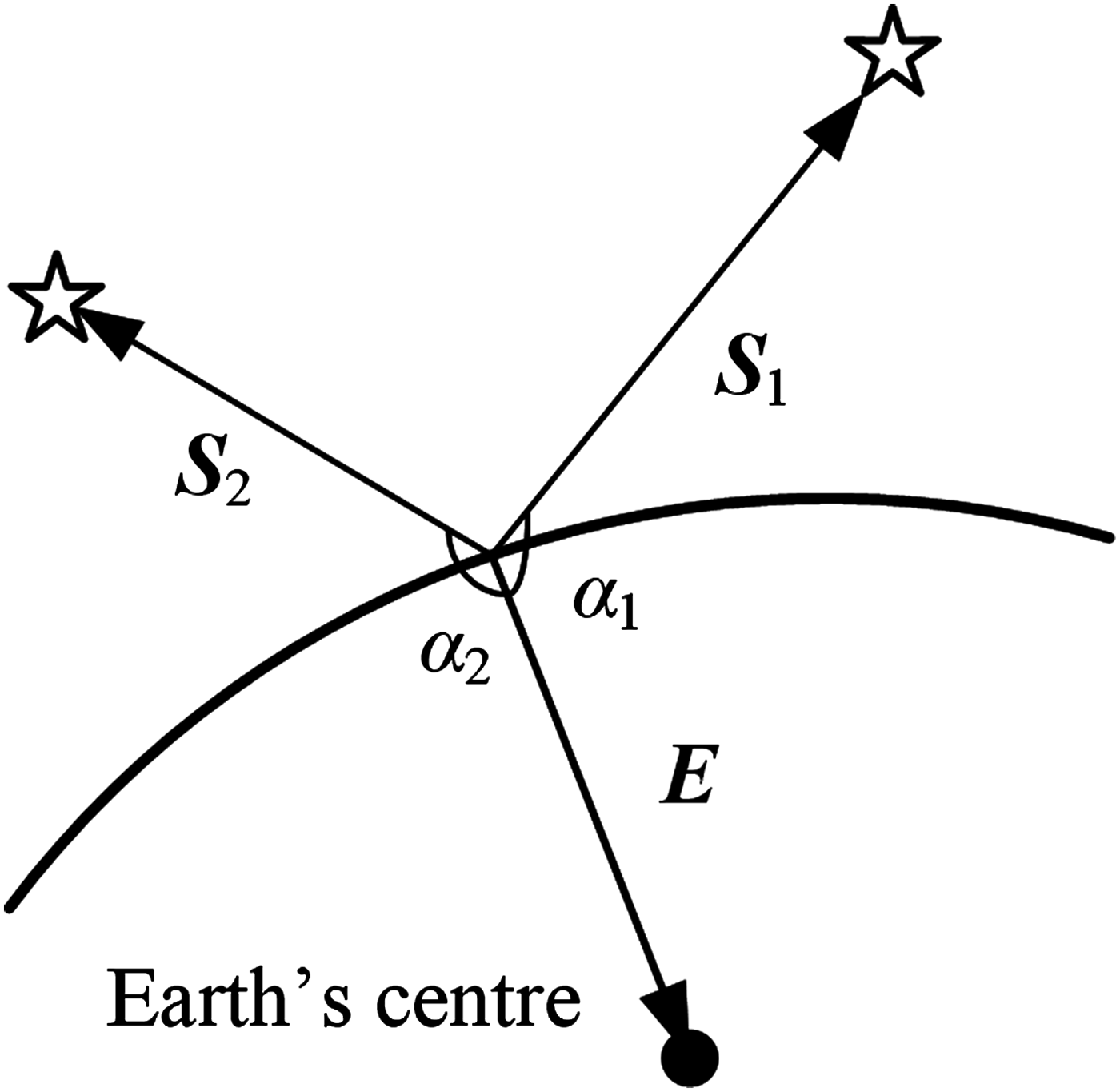
As shown in Figure 6, the navigation system can obtain two star vectors S 1, S 2 and geocentric vector E by using the star sensor and Earth sensor to observe stars and the Earth, respectively.
The principle of the navigation scheme.
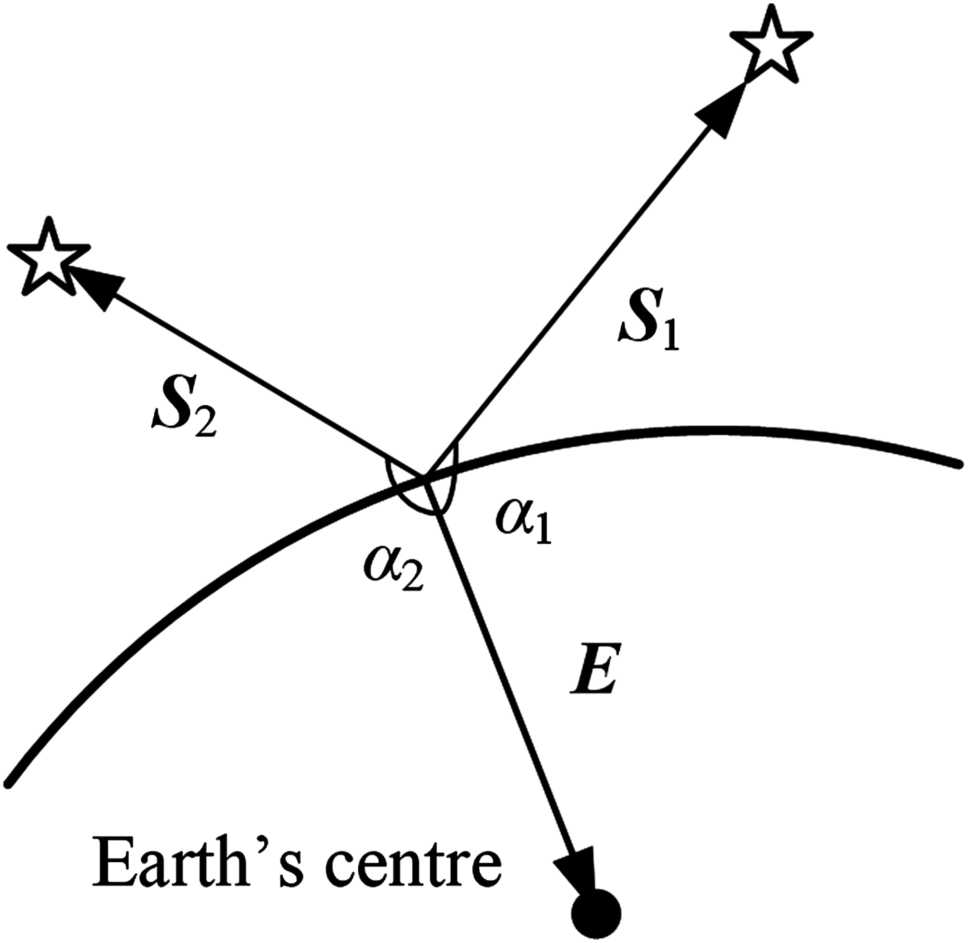
Assume that the three vectors observed by sensors are
 ${\hat{\bi S}_1}$
,
 ${\hat{\bi S}_2}$
and
 $\hat{\bi E}$
. According to the transformation relation of measurement coordinate system and body-fixed coordinate system, we can get the angular separations of the star and the Earth.
 $$\eqalign{& {{\hat \alpha} _1} = \arccos \lt {{\hat{\bi S}}_1},\hat{\bi E} \gt \cr & {{\hat \alpha} _2} = \arccos \lt {{\hat{\bi S}}_2},\hat{\bi E} \gt}$$
The two angular separations above can be utilised as measurement equations of autonomous navigation. Then we can achieve autonomous navigation by using a filtering algorithm and combining ephemeris and dynamic equations of the missile.
4.2. Determination of Star Vectors
Assume that the projected coordinate values of starlight on the Charge-Coupled Device (CCD) area array are p x and p y , respectively. The optical system focal distance is f S . Then the components of the star vector in the measurement coordinate system are:
 $${{\bi S}_m} = \displaystyle{1 \over {\sqrt {\,p_x^2 + p_y^2 + f_S^2}}} \left[ {\matrix{ { - {\,p_x}} \cr { - {\,p_y}} \cr {{\,f_S}} \cr}} \right]$$
Since the star sensor is a type of high precision instrument whose precision can reach arc second scale, the main influence factor for its measurement precision is installation precision. The installation parameters can be calibrated before launch.
4.3. CNS Based on the Angular Distances
We use the batch processing least square method to achieve autonomous navigation. Choose position, velocity and constant bias of accelerometers at the end of the powered phase as state variables:
 $${\bi \xi} = {[{{\bi r}_0},{{\bi v}_0},\Delta {\bi g}]^T}$$
The estimated Δ g can be used for correcting the constant bias of accelerometers. The theoretical values of S 1 and S 2 can be obtained by referring to the ephemeris and the calculated angular separations are given by
 $$\eqalign{& {\alpha _1} = \arccos \lt {{\bi S}_1},{\bi E}{\rm (}{\bi \xi} {\rm )} \gt \cr & {\alpha _2} = \arccos \lt {{\bi S}_2},{\bi E}{\rm (}{\bi \xi} {\rm )} \gt}$$
The observations contain errors caused by the atmospheric radiance error. To correct the errors, the geocentric vector
 $\hat{\bi E}$
obtained by the Earth sensor can be calculated and corrected by referring to Equation (13). Then, the correction observations
 $({\hat \alpha _1},{\hat \alpha _2})$
are obtained by Equation (14). The residual equations are given by:
 $${\bi g}({\bi \xi} ) = \left[ {\matrix{ {{\alpha _1} - {{\hat \alpha} _1}} \cr {{\alpha _2} - {{\hat \alpha} _2}} \cr}} \right]$$
The estimation errors of the state variables ξ decide the value of the residual. Assuming that the residual g i ( ξ ) are calculated during N sampling time, the least square index is derived by:
 $$J = \sum\limits_{i = 1}^N {{{\bi g}_i}^T {{\bi g}_i}}$$
The iterative estimation algorithm is derived by the extremum conditions of least square:
 $${{\bi \xi} _{k + 1}} = {{\bi \xi} _k} - {\bi A}_k^{ - 1} {{\bi B}_k}$$
where:
 $$\eqalign{& {{\bi A}_k} = \sum\limits_{i = 1}^N {\displaystyle{{\partial {\bi g}_i^T} \over {\partial {{\bi \xi} _k}}}\displaystyle{{\partial {{\bi g}_i}} \over {\partial {{\bi \xi} _k}}}} \cr & {{\bi B}_k} = \sum\limits_{i = 1}^N {\displaystyle{{\partial {\bi g}_i^T} \over {\partial {{\bi \xi} _k}}}{{\bi g}_i}({{\bi \xi} _k})}}$$
Generally, the iteration stops after four or five processes when the norm of the difference between present estimation and last estimation meet the requirement of precision. Then the present estimation ξ * is the precise navigation result. To improve the accuracy of the inertial navigation system, the initial values of the integral are reloaded by the estimated results r 0 and v 0, and the estimated Δ g can be used for correcting the constant bias of the accelerometers.
5. SIMULATION RESULT
In this section, the numerical results for verifying the compensation effect and the effectiveness of the navigation algorithm are presented. A standard ballistic trajectory will be given and the flight time is 1200 s. The semi-cone angle of the Earth sensor scanning cone is γ = 40° and the period of scanning is T S = 2 s. The constant bias of accelerometers is 1·5 × 10−3 m/s2. The measurement error of the star sensor is 5″(3σ). The integrated navigation system works at the passive flying phase of the ballistic missile and estimates the navigation information to modify the error of the SINS.
Firstly, a comparison between the proposed SINS/CNS method and the traditional INS method can be made with the constant bias of accelerometer only. The comparison results are shown in Table 1.
Navigation error comparison of different methods.

It is noted that the re-entry position and velocity errors of the traditional method are much higher than those of the proposed one. The proposed method can estimate the state and constant bias of accelerometer precisely without other error. If the navigation error caused by SINS and the constant bias of the accelerometer can be compensated by estimation, the accuracy of SINS will be improved further at the re-entry flying phase.
Then the asymmetry of infrared radiance should be considered to illustrate the proposed method can improve accuracy by correcting the infrared radiance error. In addition, the other method (Alex and Shrivastava, Reference Alex and Shrivastava1989) is introduced to give a comparison. Actually, this method presents an empirical formula to compensate the attitude error, but we can derive the correction by the cosine theorem of spherical triangle and denote this method as a polynomial correction.
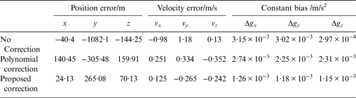
The initial state parameters at re-entry point can be estimated by using the least square navigation algorithm. Then we use the proposed compensation method and polynomial method to correct the calculated geocentric vector, respectively. The constant bias Δ g and the errors of estimation position and velocity without and with correction are shown in Table 2.
Comparison of estimation states.
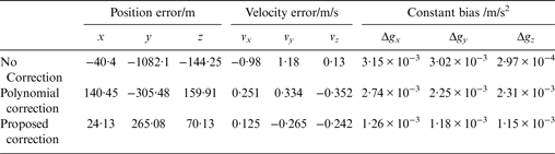
As can be seen from the results, the error of estimation position and velocity are about 1 km and 1 m/s without the correction of Earth infrared radiance error. Also, the constant bias of accelerometers cannot be estimated exactly. If the Earth infrared radiance error is corrected by polynomial correction, the error of estimation position and velocity are about 200 m and 0·3 m/s, respectively. The proposed correction method can reduce the error of estimation position and velocity to about 100 m and 0·2 m/s, respectively. The constant bias of accelerometers is about 1·2 × 10−3 m/s2 so that the error can be compensated by 80%. These estimation errors after correction are smaller than the results of SINS or polynomial correction. In this way, the proposed compensation scheme for Earth infrared radiance can effectively improve the accuracy of the SINS/CNS integrated navigation system by correcting the influence on the geocentric vector determination caused by the error of Earth infrared radiance.
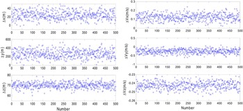
The navigation accuracy with the noise of the star sensor was examined by Monte Carlo simulation over 500 repetitions. The simulation results are shown in Figure 7 and Table 3.
Distribution of initial states of estimation. Left: position; Right: velocity.

Statistical results of Monte Carlo.

From the simulation results, we can calculate that the means are small, which implies that the error of the Earth infrared radiance is well corrected. The standard deviation of position and velocity are 100 m and 0·12 m/s, respectively, which means the navigation accuracy is high.
6. CONCLUSION
This paper researched autonomous navigation of ballistic missiles with the consideration of Earth infrared radiance error. According to the error model of infrared radiance, the relationship between Earth radiance and effective horizon height is established. The correction of the geocentric vector was given based on the geometric measurement principle of the Earth sensor. Combining with the star sensor's measurement, the position and velocity of re-entry point and constant bias of the accelerometer are estimated by using the least squares method. The simulation results showed that the compensation scheme can reduce the influence caused by infrared radiance error. The precision of position and velocity estimations are better than 100 m and 0·12 m/s, respectively. The estimated accelerometer bias can correct the partial error. The proposed integrated navigation scheme of a ballistic missile focusing on Earth infrared radiance error can improve the accuracy of navigation.