Introduction
Additive manufacturing (AM) or 3D printing has been increasingly explored for the realization of microwave passive components and antennas [Reference Zhang, Guo, Zirath and Zhang1, Reference Otter and Lucyszyn2]. In particular, the 3D components (i.e. based on rectangular-, circular-, or ridge waveguide guided-wave media) of the RF systems are manufactured as split-blocks of plastic-/resin-based parts [Reference Venanzoni, Tomassoni, Dionigi, Mongiardo and Sorrentino3–Reference Johann, William, Aurélien, Olivier, Nicolas, Bila, Serge, Jean-Baptiste and Gramond10] or as fully metallic sintered blocks [Reference Chio, Huang and Zhou11–Reference Garcia, Rumpf, Tsang and Barton17]. Metal-based AM processes such as direct metal laser sintering (DMLS) [Reference Chio, Huang and Zhou11], selective laser sintering/melting [Reference Zhang and Zirath12–Reference Peverini, Lumia, Calignano, Addamo, Lorusso, Ambrosio, Manfredi and Virone15], binder jetting [Reference Rojas-Nastrucci, Nussbaum, Weller and Crane16], and electron beam melting (EBM) [Reference Garcia, Rumpf, Tsang and Barton17] facilitate the realization of RF components with high mechanical strength and are potentially suitable for monolithic integration. However, they are expensive and result in high surface roughness, limiting their applicability to low-frequency RF applications. For example, in [Reference Garcia, Rumpf, Tsang and Barton17], two EBM manufactured Ku-band horn antennas exhibited a measured surface roughness of 40 μm RMS, which led to 1 dB of additional loss at 15 GHz. Plastic/resin-based AM manufacturing processes such as stereolithography apparatus (SLA) [Reference Le Sage18–Reference Li, Li, Zhang, Wang, Xu and Xiao34] result in significantly lower surface roughness, lower loss and weight. As an example, the SLA-based slot waveguide antenna in [Reference Le Sage18] exhibited 1 dB higher gain compared to the same antenna when manufactured with the DMLS process. However, due to the lack of conductive resins, the majority of the SLA-based passive components are manufactured as copper-plated split blocks [Reference D'Auria, Otter, Hazell, Gillatt, L-Collins, Ridler and Lucyszyn19–Reference Menargues, G-Vigureas, Debogovic, Capdevila, Dimitriadis, Rijk and Mosig22] and are assembled with screws which increase their size, weight, and loss. Monolithic SLA-based integration concepts have been discussed in [Reference Borgne, Cochet, Haumant, Diedhiou, Donnart and Manchec27, Reference Guo, Shang, Li, Zhang, Lancaster and Xu32, Reference Laplanche, Tantot, Delhote, Périgaud, Verdeyme, Bila, Baillargeat and Carpentier33] for a sub-array module, a X-band and Ka-band bandpass filters (BPFs). However, they are based on open-ended waveguides that can be readily manufactured as single monolithic blocks. Monolithic lithography-based ceramic manufacturing techniques have also been proposed for the fabrication of dielectric resonator filters [Reference Li, Li, Zhang, Wang, Xu and Xiao34–Reference Carceller, Gentili, Reichartzeder, Bösch and Schwentenwein37]. Nevertheless, the operation of this type of filters does not require the metallization of inner filter surface.
In RF systems where compact and spurious-free RF filters are needed, coaxial cavity resonator-based configurations are typically employed [Reference Mansour38–Reference Zalabsky and Hnilicka43]. However, due to their closed-form geometry, they cannot be easily manufactured as monolithic blocks. All of the SLA-based BPFs to date have been made out of multiple parts [Reference López-Oliver, Tomassoni, Silvestri, Bozzi, Perregrini, Marconi, Alaimo and Auricchio44–Reference Psychogiou and Deng50]. For example, an SLA-based S-band vertical-integrated multi-part coaxial cavity filter was demonstrated in [Reference López-Oliver, Tomassoni, Silvestri, Bozzi, Perregrini, Marconi, Alaimo and Auricchio44]. However, it exhibited high insertion loss (IL) of about 1.3 dB that corresponds to an effective quality factor (Qeff) of 100. In [Reference Venanzoni, Dionigi, Tomassoni and Sorrentino47], a 1.9 GHz SLA-based coaxial cavity BPF with mixed electromagnetic (EM) coupling was reported. Although it exhibited a fairly high Q eff (600), its assembly required multiple screws that increased its overall size and weight. In yet another approach, a hybrid-integrated SLA-based tunable coaxial cavity BPF was demonstrated in [Reference Psychogiou and Deng50]. RF tuning was achieved by attaching a varactor PCB-based tuner on top of the coaxial resonators with screws. Taking into consideration the split-block assembly limitations, this paper investigates the potential of a monolithic SLA-based integration method for coaxial-resonator-based BPFs and RF diplexers. In particular, it explores the applicability of perforated coaxial resonators [Reference Zhao and Psychogiou51] and coupling elements for the realization of single- and dual-band BPFs and RF diplexers with increased complexity.
The paper is organized as follows: In section “Single-band coaxial BPFs and diplexers”, the monolithic integration concept for SLA-manufactured coaxial cavity resonators is presented. Furthermore, its application to the design of a single-band BPF and a single-band RF diplexer is discussed in detail through coupled-resonator-based synthesis, EM simulations and experimental testing of two manufactured prototypes at C-band. Section “Dual-band coaxial BPFs and diplexers” presents the designs and experimental validations of a dual-band BPF and an RF diplexer. Finally, section “Conclusion” details the main contributions of this work. Compared to the author's previous work [Reference Zhao and Psychogiou51], this paper has expanded the monolithically integrated two-pole BPF to dual-band BPF and single/dual-band diplexers. Design considerations including the novel external coupling network and coaxial T-junctions are presented for the monolithic integration of the proposed devices.
Single-band coaxial BPFs and diplexers
Monolithic integration concept
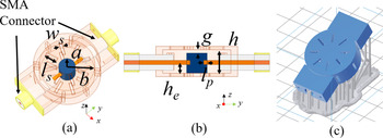
The configuration of the capacitively-loaded coaxial cavity resonator is shown in Fig. 1. It has been designed using the design method in [Reference Anand and Liu52]. Non-radiating perforations are added on the top, bottom, and side walls of the cavity resonator so that the Cu-plating solution can flow inside the SLA-manufactured part during the metallization process. RF signal is injected into the cavity by connecting the inner conductor of the SMA connector to the capacitive post. To ensure stable connection, a small hole with depth lp [Fig. 1(b)] is added in the center post. To minimize the radiation loss, the location, size, and orientation of the slots were selected so that they do not interrupt the surface current flow. This is shown in [Reference Zhao and Psychogiou51] where the current flow on the resonator walls is compared before and after adding the slots. The current flow is similar to the case of the fully enclosed cavity due to the slots being added in parallel to the current, resulting in small radiation loss at the design frequency and an unloaded quality factor Q of 3379 as opposed to 3399 in the fully enclosed case.
Monolithically-integrated coaxial cavity resonator with non-radiating slots. (a) Bird eye view of the EM model. (b) Side view of the EM model. (c) Bird eye view of the CAD printing model (blue area: filter body; grey area: support structure). The slots are for the purpose of facilitating the metallization process. The resonator dimensions are: a = 3, b = 10, g = 1, h = 7, h e = 3.5; all units are in mm.

Single-band two-pole BPF
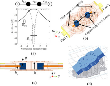
Using as a basis of the monolithic integrated coaxial cavity resonator in section “Monolithic integration concept”, a two-pole BPF was designed. Its coupling routing diagram (CRD), synthesized response, 3D EM, and CAD model for 3D printing are shown in Fig. 2. For a desired fractional bandwidth (FBW), e.g. 15%, the external coupling Qe is first calculated using (1) where k 0,1 is the normalized coupling coefficient (equal to 1 in this case).

Two-pole coaxial cavity-resonator based BPF with perforated walls to enable the Cu-platting process. (a) CRD and synthesized response (white circle: source and load; black circle: resonating node. k 0,1 = 1, k 1,2 = 0.8). (b) Bird eye view. (c) Side view. (d) 3D CAD model for 3D printing. The BPF dimensions are: a = 3, b = 10, g = 1, h = 7, h e = 3.5, d = 14, all units are in mm.

In the physical structure, Qe is materialized by connecting the inner conductor of the SMA to the capacitively-loaded post. Its magnitude is controlled by the height of the connecting position he. As shown in Fig. 3(a), as he increases, k 0,1 increases; this is primarily a result of the electric field being stronger between the post and the upper resonator wall due to the capacitively loading effect. The control of inter-resonator coupling, k 1,2, is determined by the distance d between the two posts. As shown in Fig. 3(b), the k 1,2 will increase as the distance between the two posts decrease. Using as a basis of these parametric plots, the distance of the resonators and the location of the connecting location of SMA connector are selected for the desired FBW as shown in Figs 3(b) and 3(c). Slots are also present in this case to facilitate the Cu-platting solution to flow within the filter volume. The EM-simulated response of the designed BPF for a center frequency (fcen) of 5.3 GHz and FBW of 15% is shown in Fig. 4.
(a) Qe and k 0,1 as a function of he and (b) k 1,2 as a function of d for the single-band BPF in Fig. 3.

RF-measured and EM-simulated response of the single-band coaxial-resonator based BPF in Fig. 3.

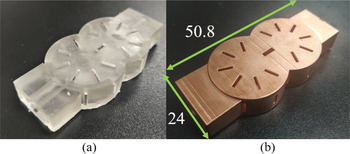
To validate the practical viability of the monolithic concept, a prototype was manufactured using as a basis the 3D CAD model in Fig. 2(d) and a desktop SLA-based 3D printer with 25 μm layer resolution. For its metallization, a Cu-platting commercial process (from RepliForm, Inc., Baltimore, Maryland, USA) with 50 μm metal layer thickness (>20x skin depth at design frequency) was employed. To compensate for the copper layer thickness, a 50 μm is employed in all geometrical dimensions in the final CAD model for SLA 3D printing. The manufactured prototype (before and after Cu-plating) of the two-pole filter is shown in Fig. 5. Its RF-measured response was characterized with a Keysight N5224A PNA and is shown in Fig. 4. It exhibits the following RF characteristics: fcen = 5.25 GHz, minimal in-band IL = 0.25 dB, and 3 dB FBW = 13%, which corresponds to an effective quality factor of Qeff = 500. Overall, the RF-measured performance is in good agreement with the EM-simulated one, successfully validating the proposed monolithic integration concept.
Manufactured prototype of the single-band filter using as a basis the BPF model in Fig. 3. (a) Before Cu-plating. (b) After Cu-plating.

Single-band diplexer
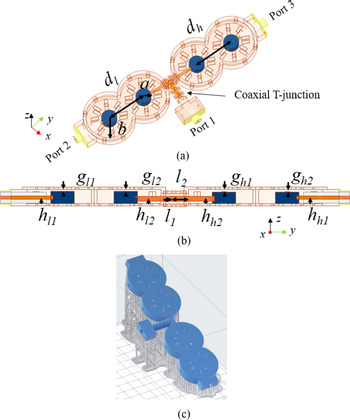
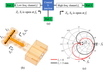
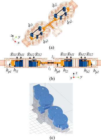
To explore the applicability of the monolithic coaxial-resonator concept to the design of more complex frequency-selective RF components, an RF diplexer configuration consisting of two two-pole BPFs was designed and is shown in Fig. 6. The design uses a coaxial transmission line-based T-junction for size compactness which is shown in this implementation for the first time. To better illustrate the design methodology for the diplexer, the circuit is divided into two sections: (i) the single channel BPF and (ii) the T-junction. Although the single channel filter design mainly follows the approach described in section “Single-band two-pole BPF”, when the BPF is integrated into the RF diplexer, one of its external couplings (e.g. RF port 2 in Fig. 2) needs to be materialized as an air-filled coaxial transmission line as opposed to the Teflon-filled case in the conventional single channel, so that the overall RF diplexer can be manufactured monolithically as shown in Fig. 6. As a result, the difference in the external coupling needs to be compensated by adjusting the connection point height of the inner conductor of the air-filled coax (hl 2 and hh 2) as shown in Fig. 6(b).
Single-band RF diplexer. (a) Bird eye view of the 3D EM model. (b) Side view of the 3D EM model. (c) 3D CAD printing model. The dimensions of the diplexer are as follows: a = 5, b = 15, g l1 = g l2 = 0.8, g h1 = 1.1, g h2 = 1.12, l 1 = 3, l 2 = 4.6, h = 6, h l1 = h h1 = 2.5, h l2 = h h2 = 2, d l = 26.9, d h = 26.7, all units are in mm.

The details of the T-junction design are shown in Fig. 7. Similar to the coaxial cavity resonator, non-radiating holes were added to the outer conductor to facilitate the Cu-platting process. In order for both bands to be matched and to maximize the isolation of the different channels, the T-junction must be designed so that the input impedance of the low-band channel (Zl) presents an RF open at the higher frequency band (fh) and the input impedance of the high-band channel (Zh) presents an RF open at the lower frequency band (fl) [Reference Basavarajappa and Mansour54]. To satisfy this condition, the phase of the T-junction needs to be properly designed. As shown in Fig. 7(c), Zl presents an RF open at fh = 4.2 GHz when l 1 = 3 mm. Similarly, l 2 is selected to be equal to 4.6 mm for Z h to present an RF open at f l = 3.3 GHz.
(a) Design principle of the T-junction. (b) EM model of the proposed T-junction. (c) Simulated reflection coefficient of the lower frequency channel Sl of the T-junction.

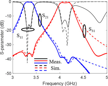
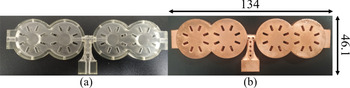
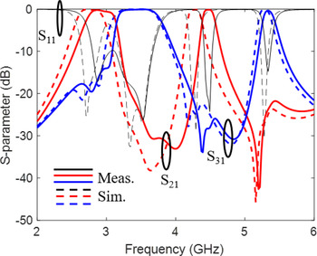
To validate the RF diplexer concept, a prototype was designed with the following RF characteristics (Fig. 8). Low channel: center frequency f l = 3.3 GHz, FBW = 7.5%; high channel: center frequency fh = 4.2 GHz, FBW = 7.5%. The RF-measured S-parameters and manufactured prototype are respectively shown in Figs 9 and 10. The RF-measured characteristics are summarized as follows: low channel: fl = 3.35 GHz, minimal in-band IL = 0.34 dB, and 3 dB FBW = 7.16%, corresponding to an effective quality factor of Qeff = 580; high channel: fh = 4.12 GHz, minimal in-band IL = 0.62 dB, and 3 dB FBW = 7.52%, which corresponds to an effective quality factor of Qeff = 330. The lower Qeff in the high-frequency channel is attributed to the surface roughness of Cu-plating. Nevertheless, the measured RF performance is in a fair agreement with the EM-simulated S-parameter response, successfully validating the RF diplexer concept.
RF-measured and EM-simulated S-parameters of the single-band coaxial-resonator-based diplexer in Fig. 7.

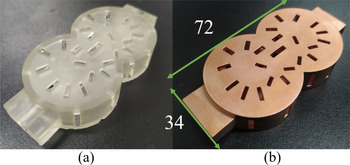
Manufactured prototype of the single-band coaxial-resonator-based RF diplexer, based on the EM model in Fig. 7. (a) Before Cu-plating. (b) After Cu-plating.

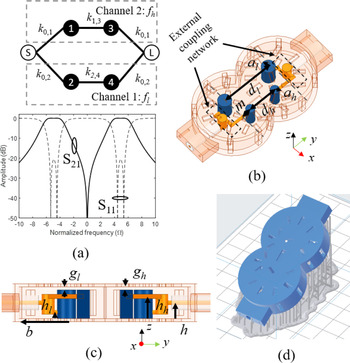
Dual-band coaxial-resonator-based BPF. (a) CRD and synthesized response (k 0,1 = 1, k 0,2 = −1, k 1,3 = k 2,4 = 1, k 1,1 = k 3,3 = −k 2,2 = −k 4,4 = 5). (b) Bird eye view. (c) Side view. (d) 3D CAD model used for SLA 3D printing. The indicated dimensions are as follows: a l = 3, a h = 2, d l = 24.2, d h = 13.6, m = 5.3, g l = g h = 1, h l = 2, h h = 7, h = 5. All units are in mm.

Dual-band coaxial BPFs and diplexers
This section explores the applicability of the monolithic SLA integration concept to dual-band BPFs and RF diplexers using as a basis a dual-resonant coaxial resonator configuration. In what follows, the design details and practical validation of the concept are discussed.
Dual-band BPF
The dual-band coaxial BPF concept is based on the CRD and its corresponding synthesized response in Fig. 10(a). Its practical development, as shown in Figs 10(b)–10(d), uses as a basis a dual-resonant coaxial resonator [Reference Liu, Katehi and Peroulis53] that is materialized by two capacitively-loaded posts (al and ah) that control the resonant frequency of each of the BPF passbands (fl and fh). In order for the bandwidth of the two passbands to be independently controlled, both the external coupling factor (Qel and Qeh) and the inter-resonator coupling factor (k 1,3 and k 2,4) of each band need to be altered individually. In particular, for the external coupling, a two-section network allowing for the SMA connector to connect to two different locations of the two posts (hl, hh) has been developed and is illustrated in Fig. 10(b). As shown in Fig. 11, hh majorly affects Qeh whereas hl majorly affects Qel. The inter-resonator coupling (k 1,3 and k 2,4) can be controlled by altering the separation of the posts. In particular, the coupling at the higher passband k 1,3 is majorly affected by the distance (dh) and the coupling k 2,4 by the distance dl as shown in Fig. 12.
External coupling factor for the low-frequency band (Qel) and for the high-frequency band (Qeh). (a). Dependence on hh. (b) Dependence hl.

Inter-resonator coupling for the high-frequency band k 1,3 and for the high-frequency band k 2,4. (a) Dependence on dh . (b) Dependence on dl.

Using as a basis these design guidelines, a dual-band BPF was designed for the following RF characteristic: low-frequency passband: fl = 3.5 GHz, FBW = 13%, high-frequency passband: fh = 5.2 GHz, FBW = 4%. Its EM-simulated response is provided in Fig. 13.
RF-measured and EM-simulated S-parameters of the dual-band coaxial-resonator-based BPF in Fig. 11.

To validate the dual-band BPF concept, a prototype was manufactured using a desktop SLA 3D printer and is shown in Fig. 14. Its performance was characterized by means of S-parameters and is shown in Fig. 13 alongside its corresponded EM-simulated response. Its RF-measured performance can be summarized as follows: low-frequency passband: center frequency fl = 3.34 GHz, minimal in-band IL = 0.32 dB, 3 dB FBW = 11.1%, corresponding to Qeff = 420; high-frequency passband: center frequency fh = 5.04 GHz, minimal in-band IL = 0.84 dB, and 3 dB FBW = 2.6%, corresponding to Qeff = 670. The observed frequency shift can be attributed to the fabrication tolerance especially in the capacitive gap (gl and gh). Overall, the simulation and measurement exhibit fair agreement with measured return loss >13 dB in both bands.
Manufactured prototype of the dual-band coaxial-resonator-based dual-band BPF based on the CAD model in Fig. 8. (a) Before Cu-platting. (b) After Cu-platting.

Dual-band RF diplexer
Using as a basis the dual-band BPF concept in section “Dual-band BPF”, an RF diplexer with two second-order dual-band channels has been designed and is shown in Fig. 15. It is comprised of three parts, i.e. two dual-band second-order BPFs and a coaxial transmission line T-junction. Similar to the channel design of the single-band diplexer, each of them needs to be re-designed so that one of its RF ports is air-filled prior to be incorporated into the RF diplexer. The redesign is achieved by tuning the height of the coupling network, namely hp 0, hp 1, and hp 2. After designing the two channels, the T-junction of the diplexer is designed in a similar way as the one described in Fig. 7(a). The EM-simulated response is provided in Fig. 16.
(a) Bird eye view and (b) side view of the proposed dual-band coaxial cavity resonator-based diplexer. The indicated dimensions are as follows: a l = 3, a h = 2, d 1 = 21.5, d l2 = 26.4, d h1 = 11.5, d h2 = 16.4, g l11 = g h11 = 1.2, g h12 = 1.75, g l12 = 0.9, g l21 = g l22 = g h22 = 0.5, g g21 = 0.47, h l1 = h l2 = 2, h h1 = h h2 = 8, h p0 = h p1 = h p2 = 5. All units are in mm.

RF-measured and EM-simulated S-parameters of the dual-band RF diplexer in Fig. 16.

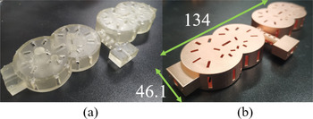
A photograph of its manufactured prototype is provided in Fig. 17 and its RF-measured performance is plotted in Fig. 16. It is summarized as follows: channel 1: low-frequency band: center frequency fl 1 = 2.96 GHz, minimal in-band IL = 0.24 dB, 3 dB FBW = 14.9% (Qeff = 520); high-frequency band: center frequency fh 1 = 4.48 GHz, minimal in-band IL = 0.18 dB, 3 dB FBW = 4.2% (Qeff = 800); channel 2: low-frequency band: center frequency fl 2 = 3.46 GHz, minimal in-band IL = 0.18 dB, 3 dB FBW = 18.9% (Qeff = 600); high-frequency band: center frequency fh 2 = 5.34 GHz, minimal in-band IL = 0.38 dB, 3 dB FBW = 3.56% (Qeff = 650). Although a fair agreement is obtained between the EM simulations and the RF measurements, a frequency shift can be anticipated. It is attributed to the added fabrication tolerances due to the increased complexity of the inner structure and the need for a few internal support structures for the external coupling network. These need to be removed manually prior to Cu plating, which affects the quality of the capacitive posts.
Manufactured prototype of the dual-band coaxial-resonator-based RF diplexer, using as basis the CAD model in Fig. 12. (a) Before Cu-plating. (b) After Cu-plating.

Comparison with state-of-the-art 3D printed coaxial filters
A comparison of the proposed monolithic coaxial-resonator-based BPF/diplexer concept with state-of-the-art (SOA) 3D printed coaxial BPFs is shown in Table 1. As shown, the proposed concept is the only one that allows for monolithic integration, resulting in smaller size and weight if compared to its split block counter parts, e.g. the ones in [Reference Venanzoni, Dionigi, Tomassoni and Sorrentino47]. Furthermore, it exhibits a significantly higher Qeff when compared to the split-block approach in [Reference López-Oliver, Tomassoni, Silvestri, Bozzi, Perregrini, Marconi, Alaimo and Auricchio44] and at a higher frequency due to its monolithic implementation. Furthermore, the proposed monolithic concept has been demonstrated for significantly more complex architectures than the SOA including a dual-band BPF and a single- and dual-band diplexer that are shown in this work for the first time. It should be noticed that the material for the SLA printing used in this work has a heat deflection temperature of 73.1 °C at 66 psi. For applications where high-temperature performance is required, e.g. satellite communication system, the material could be replaced with heat-resistant resin for stable operation of the device.
Comparison with the state-of-the-art 3D printed coaxial cavity-based BPFs

Ref, reference; Func., functionality; Mono., monolithic; #Band, number of bands; T.W., this work; N/A, not reported; * = estimated value, all the referred filters are manufactured using SLA 3D printing technique.
Conclusion
This paper presented the design, manufacturing, and experimental validation of 3D printed coaxial resonator-based BPFs and diplexers. They are based on a first developed SLA-based monolithic integration concept using perforated resonators and EM coupling elements. The proposed concept has been validated for low- and high-complexity RF designs, namely a single-band coaxial BPF, a single-band RF diplexer, a dual-band BPF, and a dual-band diplexer. Experimental validation of the monolithic SLA-based coaxial filter concept at S- and C-band demonstrated fair agreement with the EM-predicted performance proving the applicability of this technology for the realization of low-cost, low-loss, and low-weight compact RF filters.
 Kunchen Zhao received the bachelor's degree in Electrical Engineering from the University of Electronic Science and Technology of China in 2018 and the Master's degree in Electrical Engineering from the Ohio State University in 2019. He then joined the University of Colorado Boulder to pursue a Ph.D. in RF/Microwave engineering. His main research interests are the design of high-performance RF passive circuits.
 Dimitra Psychogiou received the Dipl.-Eng. degree in Electrical and Computer Engineering from the University of Patras, Patras, Greece, in 2008, and the Ph.D. degree in Electrical Engineering from the Swiss Federal Institute of Technology (ETH), Zürich, Switzerland, in 2013. She is currently a Professor of Electrical and Electronic Engineering at the University College Cork (UCC) and Tyndall National Institute, Cork Ireland. Prior to joining UCC, she was a Sr. Research Scientist with Purdue University, West Lafayette, IN, USA and an Assistant Professor with the University of Colorado Boulder, Boulder, CO, USA. Her current research interests include RF design and characterization of reconfigurable microwave and millimeter-wave passive components, RF-MEMS, acoustic wave resonator-based filters, tunable filter synthesis, and frequency-agile antennas. Her research has been presented in more than 160 IEEE publications and has received the 2020 CAREER award from National Science Foundation (NSF), the 2020 URSI Young Scientist Award and the Junior Faculty Outstanding Research Award from UC Boulder. Prof. Psychogiou is a Senior Member of IEEE and URSI and a member of the IEEE MTT-S Filters and Passive Components (MTT-5) and Microwave Control Materials and Devices (MTT-13) committees. Furthermore, she serves on the Technical Review Board of various IEEE and EuMA conferences and journals and is the Chair of MMT-13 and the Secretary of USNC-URSI Commission D. Prof. Psychogiou is an Associate Editor of the IEEE Microwave and Wireless Components Letters and the International Journal of Microwave and Wireless Technologies. Previously, she was an Associate Editor of the IET Microwaves, Antennas and Propagation Journal.