




No CrossRef data available.
Article contents
Comment to paper “Penetration depth and tip radius dependence on the correction factor in nanoindentation measurements” by J.M. Meza et al. [J. Mater. Res. 23(3), 725 (2008)]
Published online by Cambridge University Press: 20 March 2012
Abstract
[Meza et al. J. Mater. Res.23(3), 725 (2008)] recently claimed that the correction factor beta for the Sneddon equation, used for the evaluation of nanoindentation load-displacement data, is strongly depth- and tip-shape-dependent. Meza et al. used finite element (FE) analysis to simulate the contact between conical or spheroconical indenters, and an elastic material. They calculated the beta factor by comparing the simulated contact stiffness with Sneddon’s prediction for conical indenters. Their analysis is misleading, and it is shown here that by applying the general Sneddon equation, taking into account the true contact area, an almost constant and depth-independent beta factor is obtained for conical, spherical and spheroconical indenter geometries.
Information
- Type
- Comments and Reply
- Information
- Copyright
- Copyright © Materials Research Society 2012
References
REFERENCES
1.Meza, J.M., Abbes, F., and Troyon, M.: Penetration depth and tip radius dependence on the correction factor in nanoindentation measurements. J. Mater. Res. 23(3), 725–731 (2008).Google Scholar
2.Abbes, F., Troyon, M., Meza, J.M., and Potiron, S.: Finite element analysis of the penetration depth/tip radius ratio dependence on the correction factor β in instrumented indentation of elastic-plastic materials. J. Micromech. Microeng. 20, 65003 (2010).CrossRefGoogle Scholar
3.Sneddon, I.N.: The relation between load and penetration in the axisymmetric boussinesq problem for a punch of arbitrary profile. Int. J. Eng. Sci. 3, 47–57 (1965).Google Scholar
4.Pharr, G.M., Oliver, W.C., and Brotzen, F.R.: On the generality of the relationship among contact stiffness, contact area, and elastic modulus during indentation. J. Mater. Res. 7, 613–617 (1992).Google Scholar
5.Oliver, W.C. and Pharr, G.M.: Measurement of hardness and elastic modulus by instrumented indentation: Advances in understanding and refinements to methodology. J. Mater. Res. 19, 3–20 (2004).Google Scholar
6.King, R.B.: Elastic analysis of some punch problems for a layered medium. Int. J. Solids Struct. 23, 1657–1664 (1987).CrossRefGoogle Scholar
7.Vlassak, J.J. and Nix, W.D.: Measuring the elastic properties of anisotropic materials by means of indentation experiments. J. Mech. Phys. Solids 42, 1223–1245 (1994).Google Scholar
8.Hay, J.C., Bolshakov, A., and Pharr, G.M.: Critical examination of the fundamental relations used in the analysis of nanoindentation data. J. Mater. Res. 14, 2296–2305 (1999).CrossRefGoogle Scholar
9.Hay, J.L. and Wolff, P.J.: Small correction required when applying the Hertzian contact model to instrumented indentation data. J. Mater. Res. 16, 1280–1286 (2001).CrossRefGoogle Scholar
10.Larsson, P.-L., Giannakopoulos, A.E., Söderlund, E., Rowcliffe, D.J., and Vestergaard, R.: Analysis of Berkovich indentation. Int. J. Solids Struct. 33, 221–248 (1996).CrossRefGoogle Scholar
11.Durst, K., Göken, M., and Pharr, G.M.: Indentation size effect in spherical and conical indentation. J. Phys. D: Appl. Phys. 41, 074005 (2008).Google Scholar
12.Strader, J.H., Shim, S., Bei, H., Oliver, W.C., and Pharr, G.M.: An experimental evaluation of the constant β relating the contact stiffness to the contact area in nanoindentation. Philos. Mag. 86, 5285–5298 (2006).Google Scholar
13.Bolshakov, A., Oliver, W.C., and Pharr, G.M.: Explanation for the shape of nanoindentation unloading curves based on finite element simulation, in Thin Films: Stresses and Mechanical Properties V, edited by Baker, S.P., Ross, C.A., Townsend, P.H., Volkert, C.A., and Børgesen, P. (Mater. Res. Soc. Symp. Proc. 356, Pittsburgh, PA, 1995) pp. 675–680.Google Scholar
14.Chudoba, T. and Jennett, N.M.: Higher accuracy analysis of instrumented indentation data obtained with pointed indenters. J. Phys. D: Appl. Phys. 41, 215407 (2008).Google Scholar
15.Cheng, Y.-T. and Cheng, C.-M.: Scaling approach to conical indentation in elastic-plastic solids with work hardening. J. Appl. Phys. 84, 1284–1291 (1998).Google Scholar
16.Pharr, G.M. and Bolshakov, A.: Understanding nanoindentation unloading curves. J. Mater. Res. 17, 2660–2671 (2002).CrossRefGoogle Scholar
17.Woirgard, J. and Dargenton, J.-C.: An alternative method for penetration depth determination in nanoindentation measurements. J. Mater. Res. 12, 2455–2458 (1997).CrossRefGoogle Scholar
18.Merle, B., Maier, V., Göken, M., and Durst, K.: Experimental determination of the effective indenter shape and ε-factor for nanoindentation by continuously measuring the unloading stiffness. J. Mater. Res. 27(1), 214–221 (2012), DOI: 10.1557/jmr.2011.245.Google Scholar
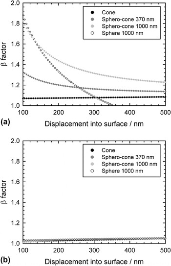
FIG. 1. Beta factor calculated (a) like Meza et al.1 by Eqs. (3) and (4), (b) by Eq. (5). Applying Eq. (5), the beta-factor collapses to a master-curve.
 You have
Access
- 1
- Cited by
I. INTRODUCTION
Meza et al.Reference Meza, Abbes and Troyon1 calculated a correction factor to the well-known Sneddon equation, which is the most important relationship in contact mechanics. The results published in 2008 are further discussed in a recent paper (2010) by Abbes et al.Reference Abbes, Troyon, Meza and Potiron2 where it is claimed that elastic and elastic-plastic experiments could give opposite trends for the correction factor.
In the present work, an almost constant and depth-independent beta factor is demonstrated, by applying the general Sneddon equation to conical, spherical and spheroconical indentations. The derivation of the equations and the naming convention follow exactly Meza et al.Reference Meza, Abbes and Troyon1 As stated by Meza et al.Reference Meza, Abbes and Troyon1 the evaluation of mechanical properties by nanoindentation is based on the SneddonReference Sneddon3 equation, valid for any axially symmetric punch of smooth shapeReference Pharr, Oliver and Brotzen4:
where S u is the unloading contact stiffness, A c the projected contact area, and E r the reduced elastic modulus. This equation was later corrected by introducing a factor β in order to account for a possible deviation from the conditions considered by Sneddon. The resulting equation has been consistently used for a decadeReference Oliver and Pharr5:
There are two distinct reasons why the correction factor β is needed. First, as KingReference King6 pointed out, commonly used indenters are not necessarily axially symmetric, leading to a first correction.Reference King6, Reference Vlassak and Nix7 Second, as Hay et al.Reference Hay, Bolshakov and Pharr8 showed, there is a deviation from Sneddon’s prediction even for the ideal elastic case of conical indentation. This is due to the inward radial displacements of the surface that have not been taken into account by Sneddon. There are numerous publicationsReference Hay, Bolshakov and Pharr8–Reference Larsson, Giannakopoulos, Söderlund, Rowcliffe and Vestergaard10 dealing with the influence of the indenter shape (tip opening angle) and material properties on the β factor as well as the respective contribution of the previously mentioned effects, see for instance the review by Oliver and Pharr.Reference Oliver and Pharr5 It has been shown indeed that the correction factor β depends on the actual contact situation (tip shape, material properties) and for spherical indenters even a depth dependency is reported.Reference Hay and Wolff9 However, values for β < 1.1 are discussed in literature, which is much smaller compared to the values reported by Meza et al.Reference Meza, Abbes and Troyon1
The present paper is based on the approach of Meza et al.,Reference Meza, Abbes and Troyon1 which includes only 2-dimensional simulations for one perfectly elastic material, with given modulus and Poisson’s ratio. As a consequence, only the effect of the radial displacements on the contact stiffness for this material is considered, and it is not possible to discuss here the influence of the 3-dimensional shape of the indenter or tip opening as well as the material properties on the correction factor.
In their paper, Meza et al.Reference Meza, Abbes and Troyon1 performed FE simulations of purely elastic indentations on fused silica with axially symmetric punches of different spheroconical geometries. The simulated contact stiffness was simply derived from the load displacement data as S FEC = dP/dh, where P was the load and h the indentation depth. The β-factor is then calculated by dividing the simulated contact stiffness S FEC by the analytical contact stiffness S Sneddon predicted by Sneddon for different indentation depths.
But, instead of using the general Eq. (1) from Sneddon for calculating the contact stiffness for the considered indenter geometry, Meza et al.Reference Meza, Abbes and Troyon1 resorted to the use of Eq. (4), established by SneddonReference Sneddon3 for conical indenters:
where it is implied that the indentation depth is related to the contact depth via
Equation (4) is only valid for conical indenters and not for spheroconical or spherical indenters. At the same indentation depth, a spheroconical indenter exhibits a different contact depth and also a larger contact area compared with a conical indenter and therefore S has different values in Eqs. (1) and (4). The calculated ratio S FEC/S Sneddon is therefore not the exact value for β, but will rather overestimate it. For obtaining the correct value of β, it is necessary to evaluate the contact area of each indenter geometry. Equivalently, β can be calculated by sticking to its definition from Eq. (2):
where A c is the contact area between the indenter and the material and the contact stiffness S FEC can be readily extracted from the FE simulation.
II. FE MODELING
The approach by Meza et al.Reference Meza, Abbes and Troyon1 is reproduced here, including our own calculation of β by Eq. (5). The simulation was carried out with the general purpose FE software Abaqus. An axially symmetric mesh with about 15,000 elements of type CAX3 was used for calculating the normal frictionless contact between the rigid indenters and a purely elastic sample. The contact area and raw load were reported by Abaqus as output variables for each increment. The data were then smoothened by a fitting function, to minimize discretization effects from the mesh. As a purely elastic material, fused silica was modeled by a Young’s modulus value of 72.5 GPa and a Poisson’s ratio value of 0.17. Four rigid indenters with different geometries were simulated: A conical indenter, a spherical indenter with a radius of 1 μm, and spheroconical indenters with a tip radius of 370 nm and 1 μm and a tip opening angle of 70.3°. The indentation depth was 500 nm. Below an indentation depth of 100 nm, the contact is established with too few elements and the results are strongly dependent on the mesh refinement. Therefore this data is excluded from our analysis.
III. RESULTS AND DISCUSSION
Figure 1 shows the analysis of the beta (β) factor as a function of indentation depth according to Eq. (3). These results are similar to the one reported by Meza et al.Reference Meza, Abbes and Troyon1 where a strong dependency of β on the indentation depth and indenter tip-shape is found [Fig. 1(a)]. For the conical indenter, β is relatively constant, while the largest discrepancy is found for the largest tip radii. This is expected, since a large tip radius leads to a strong underestimation of the contact area using Eq. (4).
Beta factor calculated (a) like Meza et al.Reference Meza, Abbes and Troyon1 by Eqs. (3) and (4), (b) by Eq. (5). Applying Eq. (5), the beta-factor collapses to a master-curve.
Analyzing the same data set using Eq. (5), the situation looks quite different. Using the contact area and thus considering the correct tip shape function for the individual indenters, the β factor becomes relatively constant and depth-independent. Besides small variations the β factor falls into the same range of 1.02–1.05 for all indenter geometries. The correction factor for the Sneddon equation is therefore on the regarded scale, fairly independent of the tip-shape and the indentation depth and the analysis of load-displacement data in nanoindentation experiments is valid for the discussed contact situation. For different material parameters, the situation might be more complex. However, a detailed discussion of these effects is beyond the scope of the present commentary.
The apparent difference between the two approaches of analyzing the contact stiffness clearly shows the necessity of considering the true contact area as the key parameter for contact mechanics experiments. This is also of great importance when comparing hardness values and size effects for spherical and conical indenters.Reference Durst, Göken and Pharr11 Analyzing the results simply by the contact depth can cause misleading interpretations of the underlying effects.
IV. CONCLUSION
In the current approach, limited 2-dimensional elastic simulations of indentations were performed for different spherical, conical and spheroconical indenter geometries. By analyzing the corresponding FE simulations, it was found that the β factor of the Sneddon equation has an almost constant value regardless of the indentation depth or the considered geometry of the indenter. This result, as well as the range 1.02–1.05 for β, is in line with the experimentsReference Strader, Shim, Bei, Oliver and Pharr12 and FE simulationsReference Bolshakov, Oliver, Pharr, Baker, Ross, Townsend, Volkert and Børgesen13–Reference Cheng and Cheng15 performed for spherical and conical indentions in elastic-plastic materials. This was theoretically expected, since it has been shown that the contact problem of an indenter pushed on a plastically deformed surface is equivalent to the one of a flat elastic surface being pressed by an indenter of a different, somewhat smoother effective shape.Reference Pharr and Bolshakov16–Reference Merle, Maier, Göken and Durst18 There is thus neither any reason nor any experimental evidence to speculate why purely elastic and elastic-plastic materials should have given opposite trends in the variation of β, as stated in Abbes et al.Reference Abbes, Troyon, Meza and Potiron2 based on the results by Meza et al.Reference Meza, Abbes and Troyon1 It is therefore reiterated again that the projected contact area is of paramount importance in contact mechanics and it is often not sufficient simply using the contact depth for analyzing the data.
ACKNOWLEDGMENT
Svitlana Rosen’s support for the FE simulations is gratefully acknowledged.