1. Introduction to superresolution
Fluorescence microscopy has contributed significantly to almost all areas of science. The use of fluorescence in microscopy applications offers chemically specific labeling and straightforward acquisition of high-contrast images. Specifically, the non-invasiveness of fluorescence microscopy made it a popular tool among biologists and medical scientists. With the emergence of superresolution microscopy in the last decade, it seems that the last obstacle in optical microscopy has been overcome, namely the diffraction limit. As all electromagnetic waves are prone to diffraction, a fundamental limit is given regarding the smallest structure that can still be resolved with light using far-field optics. This diffraction barrier has been described by Ernst Abbe in 1873 (Abbe, Reference Abbe1873). He was the first to connect the resolution capabilities of a microscope with the wavelength of light and the numerical aperture of the microscope. It took until 1994 when Hell and Wichmann published a theoretical paper, proposing how to overcome the diffraction limit in far-field optics (Hell & Wichmann, Reference Hell and Wichmann1994). The paper described a modified laser-scanning confocal microscope that exploited the quantum nature of the transition from the fluorescent (‘on’) to the non-fluorescent (‘off’) state of fluorescent molecules to carve-out a smaller point-spread-function (PSF) than the one supported by the diffraction limit. They also argued in this paper that the resolution enhancement over the diffraction barrier could in principle be unlimited.
By 1999/2000 Klar and Hell have managed to implement this concept in the laboratory and demonstrate far-field superresolution (Klar, Reference Klar2000; Klar & Hell, Reference Klar and Hell1999). This was no small feat. The paradigm-shifting concept did not go unnoticed. In a commentary to the 2000 PNAS paper, we wrote: ‘The work by Klar et al. has the potential to transform the fluorescence microscopy ‘Renaissance’ we are currently experiencing into an ‘Enlightenment Millennium.’ Our perception of the ideas put forward by Abbe over a century ago will certainly be transformed. The powerful concept of wedding nonlinear microscopies with tailored fluorophores' photophysical properties will continue to produce innovative methodologies and open novel windows into cellular dynamics. The few predictions listed above are only a small subset of what is to follow, and this beautiful story is not going to end here: the technique has even more to offer beyond live-cell imaging and biology. Spatial and temporal manipulations of the amplitude and phase of short pulses could provide coherent control of chemical reactions on the nanometer scale. Such capabilities could find uses, for example, in controlling photoresist chemistry for ultrahigh-resolution lithography, electrooptics, and magnetooptics data storage and many other nanotechnology applications. Keep your eyes open!' (Weiss, Reference Weiss2000).
In retrospect, our predictions were not too far off. Once the general idea took hold that the classical resolution limit can be broken, a whole suite of alternative superresolution techniques rapidly evolved, which were, however, all based on the very same ‘on'/‘off’ concept [for which Hell later coined the term superresolution microscopy via REversible Saturable OpticaL Fluorescence Transitions (RESOLFT)].
Today, all ‘true’ superresolution microscopy techniques (i.e. techniques which rely on the ‘on’/‘off’ properties of the label) can be roughly divided into two classes: methods like STimulated Emission Depletion (STED) microscopy, which essentially is carving-out a smaller effective PSF from a densely labeled region by turning ‘off’ a sub-population of fluorescent molecules at the PSF's rim, and methods based on the accurate localization of single molecules, by turning ‘on’ a very small sub-population of fluorescent molecules per movie frame. The latter class comprises methods such as Photo-Activated Localization Microscopy (PALM) (Betzig et al. Reference Betzig, Patterson, Sougrat, Lindwasser, Olenych, Bonifacino, Davidson, Lippincott-Schwartz and Hess2006), or Stochastic Optical Reconstruction Microscopy (STORM) (Rust et al. Reference Rust, Bates and Zhuang2006) and variants thereof, such as Ground State Depletion Imaging (GSDIM) (Fölling et al. Reference Fölling, Bossi, Bock, Medda, Wurm, Hein, Jakobs, Eggeling and Hell2008) and direct STORM (dSTORM) (Heilemann et al. Reference Heilemann, van de Linde, Schuttpelz, Kasper, Seefeldt, Mukherjee, Tinnefeld and Sauer2008). This class we will refer to as single-molecule localization techniques (SML).
A notable exception from the dependence of the photophysics of the label is structured illumination SIM (Gustafsson, Reference Gustafsson2000). However, SIM is limited to a resolution enhancement of maximum a factor of two, and despite it is commonly seen as a superresolution technique, it remains the regime of linear wave optics. In this review we will not focus on this technology.
Spectacular results have been published and seemingly no task is too difficult for superresolution imaging. Superresolution at 60 Hz has been demonstrated on cultured neurons resolving vesicle diffusion inside the synaptic gap (Westphal et al. Reference Westphal, Rizzoli, Lauterbach, Kamin, Jahn and Hell2008). A proof-of-concept for the unlimited resolution capability of STED has been given by squeezing the resolution down to 6 nm (Rittweger et al. Reference Rittweger, Han, Irvine, Eggeling and Hell2009). At the same time, SML methods have achieved very impressive results, such as the elucidation of the previously unknown organization of the integrin-based cell-adhesion complexes (Kanchanawong et al. Reference Kanchanawong, Shtengel, Pasapera, Ramko, Davidson, Hess and Waterman2010).
It is quite clear that superresolution microscopy will significantly contribute to future applications and insight of biological problems, which could not be addressed using conventional microscopy. At the same time, we should all be fully aware that superresolution microscopy comes with real costs, penalties and trade-offs.
Besides the monetary aspect (early commercial SR instruments are expensive!), superresolution imaging methods have their inherent drawbacks and challenges. For example, the extreme high light intensity levels required in STED microscopy for efficiently de-exciting fluorescent molecules may often exceed the tolerance level of living specimens, leading to the build-up of phototoxic products and eventually cell death. In contrast, SML methods usually require much lower light intensities but require long acquisition times that limit their ability to capture live cell dynamics (van de Linde et al. Reference van de Linde, Wolter, Heilemann and Sauer2010). Furthermore, to be able to perform a superresolution measurement using SML, one needs a single-molecule sensitive detector and of course the expertise to work in the single-molecule regime, which by far are not common knowledge. Also, problems arising from refractive index changes inside the sample are affecting the alignment and imaging properties of a superresolution setup, much more so than on a conventional imaging platform. For example, in the STED case, a refractive index mismatch might lead to an incomplete depletion of the fluorescent molecules, therefore, reducing the resolution. Aberrations of all kinds are problematic for both STED and SML methods. Recognizing these, Janelia farm scientists are currently working on adaptive optics solutions for aberration correction (Ji et al. Reference Ji, Milkie and Betzig2010) and for light scattering in tissue (unpublished). They are also working on novel schemes to minimize light exposure and unnecessary bleaching (Planchon et al. Reference Planchon, Gao, Milkie, Davidson, Galbraith, Galbraith and Betzig2011). Another problem that is hard to address in SML methods is how to discern underlying cellular dynamics which is faster than the temporal resolution of these methods. SML methods deliver sharp images, but whether these represent anything but artifacts remains in the hands of the expert experimenter. A priori knowledge of the sample, its dynamics, label density, and morphology of the labeled organelle/cellular structure are essential for correct interpretation of the data. Last but not least, superresolution requires specific probes, or to be more accurate specific probe properties. There is already a considerable body of work that point out to the potential problems and proposals for their solutions (Hotta et al.; Lee et al. Reference Lee, Lord, Iwanaga, Zhan, Xie, Williams, Wang, Bowman, Goley, Shapiro, Twieg, Rao and Moerner2010; Wolter et al. Reference Wolter, Endesfelder, van de Linde, Heilemann and Sauer2011). Nonetheless, when compared with conventional fluorescence microscopy, superresolution techniques remain very challenging to the non-experts. As each method has its own specific attributes and drawbacks, it might prove useful to have a whole suit of superresolution methods at hand, enabling the experimenter to choose a method that best fits his specific application.
The strength of conventional fluorescence imaging lies in its ability to monitor live cells and the underlying dynamics. The hope is, of course, that superresolution fluorescence imaging could do the same. This, however, is a very challenging task. Many live cell dynamical phenomena are fast. Even ‘slow’ diffusion processes turn out to be very fast on a small scale. In general, shorter acquisition times require from the fluorophores to emit more photons within a shorter period of time. For SML-based methods, this requirement is difficult to satisfy, since at the same time most fluorophores need to be in the ‘off’ state. Despite these limitations, several live cells superresolution imaging results have been published (Biteen et al. Reference Biteen, Thompson, Tselentis, Bowman, Shapiro and Moerner2008; Klein et al. Reference Klein, Löschberger, Proppert, Wolter, van de Linde and Sauer2011; Lee et al. Reference Lee, Lord, Iwanaga, Zhan, Xie, Williams, Wang, Bowman, Goley, Shapiro, Twieg, Rao and Moerner2010; Wombacher et al. Reference Wombacher, Heidbreder, van de Linde, Sheetz, Heilemann, Cornish and Sauer2010). Most recently, live cells SML imaging has been achieved with sub-second acquisition times (Jones et al. Reference Jones, Shim, He and Zhuang2011).
Due to the limitations discussed above, it might be necessary to trade-off speed with (super) resolution. The question that we would like to address then is, what is the optimal trade-off? Below we introduce the concept of superresolution optical fluctuation imaging (SOFI) and argue that it offers a very favorable trade-off for live-cell imaging. In Section (2) we introduce the SOFI concept, in Section (3) the theory behind it, in Section (4) we show applications of SOFI using various imaging platforms and different types of probes. In Section (5) we discuss the prospects of SOFI and its future developments, and give conclusion in Section (6).
2. Superresolution optical fluctuation imaging
We have been pursuing an approach to superresolution imaging that utilizes an alternative strategy. Rather than simultaneously or sequentially switching the molecules, we derive superresolved information from temporal, stochastic ‘on’ and ‘off’ fluorescence dynamics (‘blinking’) or any other stochastic fluctuation. The core idea behind SOFI is to find a way that blindly disentangles fluorescence (and possibly even non-fluorescent) fluctuations stemming from individual molecules. In this context it is important to note that fluorescence fluctuations can be understood in the most general way. A fluctuation arising from any fluorescence property might be used for SOFI, as long as it can be recorded. This could be polarization changes, color changes, or simply a bright and a dim fluorescent state or any combination thereof. The key to resolution enhancement by SOFI is that any fluorescent molecule does not interact with its neighbors – i.e. emitters fluctuate stochastically and independently of each other. This seems to be a natural assumption for labeling densities that are more dilute than the FRET and Dexter regimes (the average distance between probes is >10 nm). This assumption is a key requirement for SOFI; any synchronization or coupling of fluctuations (by external fields or by interactions with neighbors) would compromise the SOFI approach.
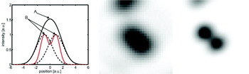
A straightforward measure of independently fluctuating stochastic signals is the correlation function. Intuitively, it is clear that a single fluctuating emitter will give rise to a highly correlated signal, whereas a mixed signal, composed of a superposition of signals coming from two or more independent emitters, will be less correlated. Moreover, when correlating the fluctuations of a signal (as opposed to measuring its amplitude), a non-correlated signal will yield a zero value, while any residual correlation will yield a positive value. The key feature of the correlation function, which is the linchpin of SOFI, is its nonlinearity (with respect to its arguments). This nonlinearity emphasizes strong, ‘pure’ (correlated) contributions and diminishes ‘mixed’ (uncorrelated) contributions, as illustrated in Fig. 1. The basic procedure for acquiring a SOFI image therefore consists of recording a movie (capturing the probes' fluctuations) and subjecting it to a simple correlation analysis. A specific realization of SOFI therefore could be the exploitation of the antibunching term in the correlation function of light emitting probes as has been recently suggested (Schwartz & Oron, Reference Schwartz and Oron2012).
Illustration of the non-linearity of the correlation function and the resulting resolution gain. Left: Two closely spaced emitters give rise to the sum signal observed at a given position (indicated by the black solid line). The red line corresponds to the amount of correlation. The black dotted lines depict the signal stemming from a single emitter only. Despite the high amplitude of the sum signal in A its correlation content is not necessary highest as depicted in this carton. The points of highest correlation are indicated in B. Here the sum signal shows the highest degree of ‘purity’. Middle and Right: Experimental realization of the working principle of SOFI. Middle: Unresolved sum signal stemming from two quantum dots. Right: Correlation signal as calculated by the SOFI algorithm. Evidently, the resolution of the SOFI image is increased with respect to the original image.

Below we briefly develop the underlying theory behind SOFI, which is explained in full detail in (Dertinger et al. Reference Dertinger, Colyer, Iyer, Weiss and Enderlein2009, Reference Dertinger, Colyer, Vogel, Enderlein and Weiss2010a):
3. SOFI theory
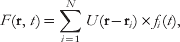
Let us assign to each emitter i a time-dependent fluctuation function fi(t), which accounts for any fluctuation that is connected to photophysics of the molecule. Then the time-dependent signal F as given for some position r by a far field microscope can be written as (assuming the emitters are not moving):
 $$F({\bf r}{\rm \comma }\,t) = \sum\limits_{i = 1}^{N} U ({\bf r} - {\bf r}_{i}) \times f_{i} (t) \comma $$
where U is the point spread function (PSF) of the microscope. Equation (1) solely describes the convolution of the PSF with the emitter distribution. The second-order correlation or second-order cumulant function of the fluctuations of F(t) = ΔF(t)−〈F(t)〉 is given by:
 $$\eqalign{ AC_{2} ({\bf r}\comma \,\tau _{1} \tau _{2}) = \left\langle {\delta F({\bf r}\comma \,t + \tau _{1} \times \delta F({\bf r}\comma \,t + \tau _{2})} \right\rangle \cr = \sum\nolimits_{i = 1}^{N} U ^{2} ({\bf r} - {\bf r}_{i}) \times \left\langle {\delta f_{i} (t + \tau _{1}) \times \delta f_{i} (t + \tau _{2}) } \right\rangle . \cr} $$
The expression in Eq. (2) denotes a convolution of a single-molecule correlation term with a squared PSF. This results in a new, narrower PSF for the AC 2 image (by a factor of  $\sqrt 2 $) i.e., the AC 2 image is superresolved. Higher resolution could be achieved by expanding this approach to higher-order cumulants, which can be derived form higher-order correlation functions (second- and third-order cumulants are identical to their second- and third-order correlation functions counterparts). Starting from the fourth order, cumulants are derived in a slightly more complex way from correlation functions (Mendel, Reference Mendel1991). The construction of a SOFI image from the nth-order cumulant will feature a PSF that is taken to the nth power therefore shrinking the SOFI image PSF by a factor of
 $\sqrt n $. This means that in principle the resolution enhancement is unbounded and will continue to improve as n gets larger and larger:
 $$AC_{n} (r\comma \,\tau \comma \ldots \comma \tau _{n}) = \sum\limits_{i = 1}^{N} {U^{n} } (r_{i} - r) \times \varepsilon _{i}^{n} \times w_{i} (\tau _{1} \comma \ldots \comma \tau _{n}) .$$
To date we could show that indeed the second-order correlation function carries a resolution gain of a factor of 2 and the nth order cumulant gives rise to an n-fold resolution enhancement.
One interesting feature of SOFI is its capability to generate additional pixels, containing additional image information. Let us assume a microscope setup, which has a magnification of 120 nm/pixel. A PSF spans, in this magnification, over 3–4 pixels. As the SOFI algorithm shrinks the PSF, at some order the PSF would be smaller than a single pixel, reflecting a resolution better than 120 nm. Any further contraction (by higher-order cumulants) will be ‘wasted’ since smaller structures would nevertheless be pooled into the same pixel, and thus remain unresolved. A possible solution would be to increase the magnification, which in turn would lead to an unfavorable photon dilution (the photons stemming from one molecule would be distributed among larger number of pixels, thus the signal-to-noise ratio (SNR) will decrease) and a smaller field of view. A better solution to this problem can be achieved by exploiting the power of cross-cumulants (the correlation of neighboring pixels' time traces) rather than computing the pixels' auto-correlation terms only (Dertinger et al. Reference Dertinger, Colyer, Iyer, Weiss and Enderlein2009, Reference Dertinger, Colyer, Vogel, Enderlein and Weiss2010a).
It can be shown that the cross-cumulant terms correspond to virtual pixels, which are located at the ‘center-of-mass’ in between the pixels that are used for the cross-cumulant calculation. For the second-order SOFI image this translates into twice as many pixels along each axes (×4 pixels for the image) and for the nth order×n 2 pixels. Note that this procedure is not a simple interpolation, which would not yield additional information. These additional ‘virtual’ pixels in turn support higher resolution images, because even though the PSF is shrinking, the spatial sampling ratio of the PSF remains the same (i.e. a twice smaller PSF, as is the case for the second-order SOFI image, will be sampled with the same number of pixels as the original PSF). Practically, as long as the magnification is originally adjusted to provide a slight oversampling of the PSF, it does not need to be readjusted for higher (order) resolution images. In contrast, when a resolution of 10 nm is set as a goal for STED, 5 nm scanning steps are required.
These ‘virtual’ pixels need to be interlaced in between pixels calculated by auto-cumulant terms. The assembly of such up-sampled SOFI image yields a very desirable byproduct. Since the cross-cumulant terms contain a prefactor that scales like the original optical PSF itself, equalizing the amplitudes of the cross-cumulant terms to those of the neighboring auto-cumulant terms in the assembled SOFI images provides a full description of the PSF, which in turn can be used for further deconvolution analysis (Dertinger et al. Reference Dertinger, Colyer, Vogel, Enderlein and Weiss2010a).
Another very important consequence of the cross-cumulant approach is that SOFI images could be calculated using solely the zero time lag. This, in principle, can be done for the auto-correlation approach as well, but in that case the zero time lag term carries shot-noise contributions which degrade the superresolved image. Since random noise is not correlated between different pixels, this contribution is completely filtered out in the cross-cumulant approach. Calculations based on zero time lag only, in turn, are very simple and fast since they contain only multiplicative terms.
Another advantage of the cross-cumulant approach is that the SOFI image becomes largely independent of the blinking-statistics. For example, a fourth-order SOFI image, which is calculated solely from the use of autocorrelations (no virtual pixels) will require four different time lag inputs in the correlation integral (in order to omit shot noise they will all have to be different). However, if the characteristic blinking time is faster than four frames (i.e. four time lags) no correlated photon events from the same emitter will be found, leading to a break-down of the SOFI algorithm. In contrast, the cross-cumulant SOFI approach does not require information from four consecutive frames, but the signals from four adjacent pixels in the same frame (covering the same PSF). Therefore, the ideal blinking rate for XC-SOFI images is on the order of the frame rate, but slower or faster dynamics will be processed efficiently too.
4. Applications
In this section, we will provide an overview of SOFI capabilities.
4.1 SOFI using various optical platforms
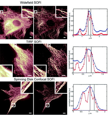
As mentioned above, SOFI works on all imaging platforms that can provide a time-lapse (movie) acquisition mode. In Figure 2, we show examples of SOFI acquired on different microscopes (conventional lamp-based Widefield microscope, TIRF microscope, and a confocal scanning microscope).
SOFI performed on various microscopes. All images are showing the tubulin network of NIH 3T3 fibroblasts immune-stained with infrared emitting quantum dots. The images on the left column correspond to the original images as acquired by the respective microscope (2000 frames). The middle column shows the corresponding second-order SOFI images and the right columns depict line profiles taken along the cross-sections as indicated in the magnified areas of each image (blue line: conventional image, red line: SOFI image). Evidently, the resolution is increased by SOFI in all cases (manifesting features that were not resolved in the original images). Upper panel: Widefield microscope. Scalebar: 5 μm. Distance between black lines in the cross-sections plot is 234 nm. Middle panel: TIRF microscope. Scalebar: 5 μm. A stray light contribution (left side of the original image) is automatically removed by the SOFI algorithm since stray light lacks fluctuations and therefore yields a zero value in the SOFI image. Quantum dots previously hidden in the stray light become clearly visible. Distance between black lines in the cross-sections plot: 245 nm. Lower Panel: Spinning Disk Confocal microscope. Scalebar 5 μm. Distance between black lines in the cross-sections plot is 266 nm.

Even though SOFI can be done on a confocal scanning microscope, this mode is certainly not the most suitable mode of SOFI, since the strength of SOFI is in its parallel acquisition and parallel image processing.
4.2 SOFI with plasmonic metal nanoparticles
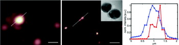
Since the SOFI algorithm works for all stochastically fluctuating signals, we tested its superresolving power for metallic nanoparticles typically used for surface-enhanced Raman scattering (SERS) measurements. Plasmonic metal nanoparticles, as used for SERS experiments, provide extremely bright and photostable probes that may be used for long-term imaging. We have developed SERS biotags (SBTs) of dimers and trimers of metal nanoparticles that are stable in biological conditions (Braun et al. Reference Braun, Lee, Laurence, Fera, Fabris, Bazan, Moskovits and Reich2009; Laurence et al. Reference Laurence, Braun, Talley, Schwartzberg, Moskovits, Reich and Huser2009, Reference Laurence, Braun, Reich and Moskovits2012; Pallaoro et al. Reference Pallaoro, Braun, Reich and Moskovits2010, Reference Pallaoro, Braun and Moskovits2011). During our measurements, we observed that these nanoplasmonic probes undergo dramatic, long-term blinking behavior. We have not determined whether these fluctuations are related to movement of single Raman tags (Jiang et al. Reference Jiang, Bosnick, Maillard and Brus2003; Nie, Reference Nie1997) or rotational motion of the nanoparticles (Laurence et al. Reference Laurence, Braun, Reich and Moskovits2012) or another cause (the cause for the blinking is currently under investigation). Regardless of the origin, dramatic blinking of these very bright, non-photobleaching signals provides the perfect candidate probes for SOFI. We imaged SBTs attached to a glass surface in aqueous solution and dry, and observed blinking behavior in both conditions. The SBTs were excited by a defocused 637 nm diode laser (Stradus 637-140, Vortran Laser, Sacramento, California, USA) and imaged using a CCD camera (Andor iXon). The movies of the blinking SBTs were processed using the SOFI algorithm. Figure 3 clearly demonstrates contrast enhancement and superresolution for the SOFI-processed data (middle panel and cross-section in right panel; the inset in the middle panel shows a transmission electron microscopy (TEM) image of an individual SBT, scalebar: 10 nm).
SOFI performed on nanoplasmonic probes. Left: Conventional microscope image. Middle: SOFI image; inset: TEM image of an SBT, scalebar: 10 nm. Right: Cross-section plot along the dashed-white line profile indicated in the images. The peak-to-peak distance is about 300 nm for the resolved feature. Scalebar: 1 μm.

The starting material for the SBTs is 50 nm monomers obtained from Ag citrate reduction in house synthesis (Lee & Meisel, Reference Lee and Meisel1982) that are aggregated via phosphate and hexamethylenediamine addition and stabilized by a combination of polyvinylpyrrolidone (40 kDa) and modified bovine serum albumin. The SBTs are infused with the resonant Raman reporter thionin and functionalized with cell targeting peptides.
4.3. SOFI with organic dyes
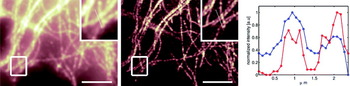
The previous examples where acquired using bright and photostable quantum dots or plasmonic metal nanoparticles. However, despite many advantageous properties of these probes, organic dyes are often the probes of choice for biological applications. It is not surprising, but nevertheless an important result that SOFI does work also on emission fluctuations exhibited by organic dyes. Here the problems of bleaching and weaker signals pose some difficulties for SOFI analysis. The bleaching problem can be overcome by block-wise processing of the acquired SOFI movie, such that in each block (of several frames only) the bleaching is negligible. Thus instead of having a single SOFI image, one ends up having many SOFI images (all of them are quite noisy), which can be added up to a final, less noisy, SOFI image (Dertinger et al. Reference Dertinger, Heilemann, Vogel, Sauer and Weiss2010b). This is shown in Fig. 4.
SOFI image of the tubulin network of immunostained HELA cells. Organic dyes (Alexa 647) have been used as probes and the blinking was induced by a specific ‘blink’ buffer and a second laser (Heilemann et al. Reference Heilemann, van de Linde, Schuttpelz, Kasper, Seefeldt, Mukherjee, Tinnefeld and Sauer2008, Reference Heilemann, van De Linde, Mukherjee and Sauer2009). Left: Original fluorescence image. Middle: SOFI image. The boxed regions are shown magnified in the upper right corner of each image. The cross-section plot (right) is taken along the dotted line as indicated in the magnified views. Blue line: original intensity profile. Red line: SOFI intensity profile. Scalebar 5 μm.

5. Discussion
We claimed above that in principle, high-order cumulants could yield higher SOFI resolution. But to what order cumulants should be calculated in practice? Even though SOFI has seemingly unlimited resolution capability, there are ‘real world’ limits. As it turns out, there are difficulties in trying to quantify these limits, since the underlying theory for cumulants is highly non-linear and analytical calculations regarding the achievable resolution enhancement are not straight forward. A more sophisticated theory would need to address the following questions: given a blinking rate, what is the optimal acquisition frame rate? Given a SNR per frame and a blinking rate, what is the optimal cumulant order for the calculations, beyond which the data set does not provide enough statistics and does not support a complete decorrelation of the higher-order cumulant terms? Although these aspects of the theory have not been worked out as of yet, resolution enhancement of up to four times have been experimentally demonstrated (Geissbuehler et al. Reference Geissbuehler, Dellagiacoma and Lasser2011). This modest enhancement falls short of the enhancement attainable by SML methods (which routinely achieve ×10 enhancement factors (at least in localization precision). If so, what are the advantages of SOFI, if any, as compared with other superresolution techniques? When is it advisable to use SOFI instead of STED or SML methods?
In general, the higher the desired resolution, the more overall photons are needed (and the better the SNR has to be). The high resolution afforded by SML methods stems from thresholding low S/N events (low signal from individual molecules as compared with background signal). Thresholding also eliminates false localizations. This, however, comes with a penalty: SML methods work only down to a certain SNR under which the number of successful localizations dramatically drops (van de Linde et al. Reference van de Linde, Wolter, Heilemann and Sauer2010; Wolter et al. Reference Wolter, Endesfelder, van de Linde, Heilemann and Sauer2011), at which point the approach is no longer workable for superresolution imaging. In contrast, SOFI has been shown to work at a five times lower SNR as compared with dSTORM (Geissbuehler et al. Reference Geissbuehler, Dellagiacoma and Lasser2011). This in turn allows for faster frame rates and shorter acquisition times. Furthermore, SML methods require probes that exhibit long ‘off’ times (∼1000 times longer as compared to the ‘on’ time) in order for the algorithm to work properly. SOFI, on the other hand, could provide superresolution at almost any arbitrary ‘on'/‘off’ ratio.
Thus, SOFI could provide added value to superresolution imaging when conditions are not optimal for SML: when (i) short acquisition times are needed, (ii) the ‘on'/‘off’ ratio of the probes cannot be tuned as needed and/or the labeling density is too high, or (iii) the SNR is not adequate for SML-based methods. It is clear, although, that relaxing these requirements will compromise the resolution attainable by SOFI as compared with the one attainable by the SML methods or STED as mentioned above. Another limitation of SOFI is the brightness scaling of higher-order cumulants, resulting in a very large dynamic range (large contrast) that cannot be displayed in an appealing way (the best look-up tables are the ones that exhibit a low contrast). The obstacle, however, has been very recently overcome by using balanced cumulants as explained in (Geissbuehler et al. Reference Geissbuehler, Bocchio, Dellagiacoma, Berclaz, Leutenegger and Lasser2012).
6. Conclusion
We have reviewed the most recent newcomer to the superresolution tool-kit, SOFI. SOFI has already demonstrated unique attributes and favorable trade-offs, providing an easy and affordable way for achieving superresolution imaging. Future applications of SOFI will address rapid live cell imaging and three-dimensional (3D) superresolution imaging. SOFI is inherently a 3D method, but some technical aspects have to be addressed first before this important capability can be demonstrated (Dertinger et al. Reference Dertinger, Xu, Foroutan, Vogel and Weiss2012). A true breakthrough in SOFI utilization is expected when proper blinking properties will be engineered into fluorescent proteins. We anticipate that the SOFI approach will be utilized beyond fluorescence imaging by taking advantage of polarization fluctuations and other non-fluorescent stochastic blinking phenomena.
Acknowledgements
We thank Robert Vogel for preparing samples and taking the quantum dots data (used in Fig. 2), Mike Heilemann and Markus Sauer at the University of Wuerzburg for providing us with the raw organic dye data (used in Fig. 4) and Martin Moskovits for advice and support. Part of this work (S. Ly and T. Laurence) was performed under the auspices of the U. S. Department of Energy by Lawrence Livermore National Laboratory under Contract DE-AC52-07NA27344. Part of this work (A. Pallaoro and G. Braun) was supported by the Institute for Collaborative Biotechnologies through Grant DAAD19-03-D-0004 from the US Army Research Office. This work (T. Dertinger and S. Weiss) was supported by NIH grant no. 5R01EB000312 and NIH grant no. 1R01GM086197.