I. INTRODUCTION
In the past decade, the 60 GHz indoor communication technology has sparked great interest, since its wide unlicensed bandwidth enables a promising high-speed datalink of more than 5 Gbit/s [Reference Baykas1]. Although some commercial solutions have already surged into consumer electronics market [2], it still sees obvious constraints in applications. Due to its particular atmospheric attenuation in free space [Reference Marcus and Pattan3] and the small wavelength, the 60 GHz radio is very keen to be blocked by obstacles (e.g. it is barely able to scatter through a wall). So current investigations just aim at the light-of-sight scenarios, and the implementations in non-light-of-sight (NLOS) environments are full of challenges. In particular, in the quite hostile indoor environment, NLOS areas can only be left blind with no signals covered. Therefore, in order to expand the radio coverage and to re-establish signal relay linkage for the indirect paths in these areas, passive repeater [Reference Hristov, Grote and Feick4] is a competent solution. In this paper, we focus on the solution based on planar and compact passive repeater with low cost, to make the integration on walls easy and non-pervasive.
Furthermore, the specific challenging scenario of T-shaped corridor is considered in this study, for being a typical example of the indoor NLOS environments. As shown in Fig. 1, an access-point is located in a main corridor (vertical branch in the figure) and aims at transmitting signals to receiving terminals (Rx terminal) in the orthogonal branches. As the receivers are masked by the corner walls, most of the incident wave is reflected back in the main corridor or absorbed by the walls. Then, power received by Rx terminal could be expected to be very low as they stand in blind NLOS areas. In order to improve the received power level and recover the communications between access-point and Rx terminal, a passive repeater can advantageously be used. It is expected to redirect the incident wave to the orthogonal branches, which requires a reflector that can produce endfire radiation when illuminated by a normally incident wave.
Endfire-radiation repeater working in the typical NLOS scenario of T-shaped corridor.

In [Reference Wang, Gillard and Loison5, Reference Wang, Gillard and Loison6], two types of such planar repeaters based on dielectric resonator antenna (DRA) elements have been proposed. Though their capabilities to provide endfire radiation were validated, the corresponding fabrication complexity requiring fine accuracy is a quite tricky issue at such high frequency (60 GHz). To solve this problem, a novel repeater was proposed in [Reference Wang, Gillard and Loison7], using parallel grooves drilled in a flat metallic plate. This topology was first proposed in [Reference Cho, Byun and Song8] for reflectarrays. It is very similar to the first historical reflectarray structure using short-ended rectangular waveguide [Reference Berry, Malech and Kenned9], except that the rectangular waveguides are replaced by parallel plate waveguides. This makes the design and the fabrication much simpler. Nevertheless, this new solution is restricted to applications where the reflected beam has to be steered in only one plane and for linear polarization, which is the case here.
In [Reference Wang, Gillard and Loison7], a repeater consisting of only six grooves was studied with numerical simulations as a preliminary step. A quasi-endfire radiation with main beams pointing to ±65° was obtained, resulting in a large amount of reflected power directed in the orthogonal branches of the corridor. In this paper, a larger reflector with 24 metallic grooves (with overall size 60 × 60 mm, i.e. 12λ 0 × 12λ 0) is first investigated numerically, in Section II. The design process is described, the performance is analyzed and the sensitivity to geometrical parameters is studied. In Section III, an 80-groove array with much larger dimensions (with overall size 200 mm × 200 mm or 40λ 0 × 40λ 0) is fabricated and measured. Preliminary validation of the array's quasi-endfire radiation is conducted in anechoic chamber. Then, a second experiment is taken in practical NLOS environment where Tx and Rx antennas are deployed orthogonally. When the distance from array to Rx antenna is 1.5 m, and to Tx is 2 m, the array exhibits main beam at ±75° with gain up to 22.7 dB. Signal is received at Rx antenna with high-power budget, and the communication between Tx and Rx antennas is thus successfully recovered. Finally, concluding remarks are given in Section IV.
II. DESIGN OF 24-GROOVE REPEATER
This section aims at analyzing the performance of a medium-size repeater using full-wave simulations.
Figure 2 gives a global view of the foreseen repeater. For the preliminary analysis, the reflecting surface is made from a 24-groove square metallic plate (in the size of 60 mm × 60 mm, or 12λ 0 × 12λ 0). The used material is aluminum (σ = 37.8 × 10⁶ S/m, ε r = 0.99 for simulations). The overall repeater size has been chosen as a trade-off between computational burden using electromagnetic simulation (Ansys HFSS in our case) and representativeness of results regarding larger reflectors (as will be studied in Section III).
Global view of endfire passive repeater.
The repeater can be seen as a 24-element linear array of grooves parallel to the y-axis. In the foreseen application, the array is assumed to be in the far-field region of the access-point, so we suppose it is excited by a normal incident wave with the x-polarized electric field. In the HFSS simulation model, the finite-size array is surrounded by an air box with radiation boundary. Two different heights (h 1 and h 2) are alternatively assigned to the consecutive grooves to produce out-of-phase reflections. Consequently, the specular reflection (at θ = 0°) is cancelled out. Moreover, as the inter-element spacing is set to λ 0/2, endfire radiation (at θ = ±90°) is achieved. More details about the working principle can be found in [Reference Wang, Gillard and Loison7].
The main design steps consist in choosing the width of the groove's cross-section (b) and the heights (h 1 and h 2) of the grooves. On one hand, the width has to be determined to control the amount of incident power entering the grooves (and thus their capability to control the reflected wave). It has been optimized as 2 mm (or 0.4λ 0) in [Reference Wang, Gillard and Loison7] by calculating the transmission in a single matched groove with local periodicity. This value is also used here. On the other hand, the heights control the reflected phases from successive grooves. As expected, proper h 1 and h 2 would produce reflection phase of 0° and 180° alternatively, and result in the minimum specular reflection with a maximum endfire radiation. During optimizations of the heights (which was conducted on the full 24-groove array), h 1 and h 2 have thus been tuned simultaneously until the ratio of the endfire to broadside reflection reaches its maximum value:
 $$\psi = \left \vert {\displaystyle{{{E_\theta} (\theta = \pm 90^{\circ}, \varphi = 0^{\circ} )} \over {{E_\theta} (\theta = 0^{\circ} )}}} \right \vert. $$
The resulting heights are optimized as h 1 = 0.48 mm (or 0.096λ 0) and h 2 = 2.3 mm (or 0.46λ 0). The corresponding optimized directivity pattern in the E-plane (E θ) is presented in Fig. 3 (black solid curve).
For the 24-groove array, comparison of the directivity patterns in the E-plane (E θ) when h 2 = 2.3 mm, h 1 = 0.48 mm, and 0.53 mm.
As can be seen, most of the reflected power is redirected close to endfire (in the main beams ranging from ±70° to ±90°, with a maximum at ±76°). Simultaneously, the reflection at broadside is significantly reduced thanks to the out-of-phase cancellation of the reflected waves from successive grooves. A tolerance analysis shows that this cancellation mechanism is very sensitive to the dimensions of the grooves. As an illustration, when a minor variation of 50 µm is applied to h 1 (h 1 is varied from optimal value, i.e. 0.48, to 0.53 mm; while h 2 is kept unchanged as 2.3 mm), the corresponding broadside reflection exhibits a 7.3 dB increase. Fortunately, the variation of the grooves’ height does not disturb the main beams at ±76°. The directivity, defined as the average value of 1/2 [D(76°) + D(−76°)], is 19.8 dB for both h 1 = 0.48 mm (black solid curve) and h 1 = 0.52 mm (red dashed curve). Even if the used technological process does not enable a perfect control of this sensitive parameter, the reflector will redirect most of the incident wave parallel to its surface. This is the most important point for the design.
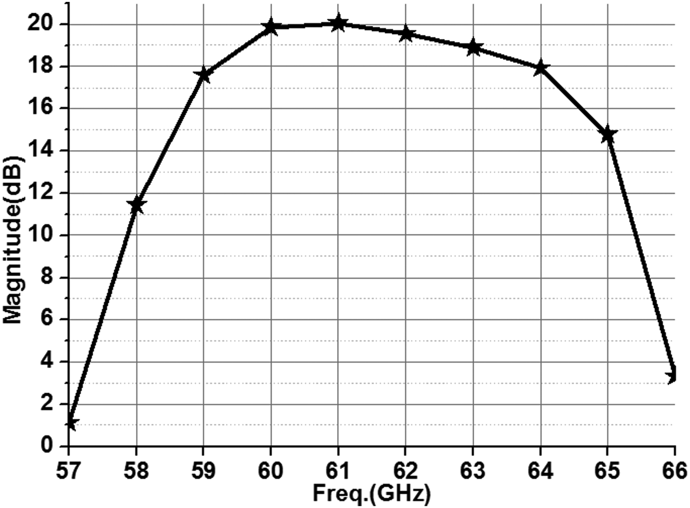
The simulated directivity (once again the average value at ±76°) versus frequency is given in Fig. 4. The maximum value of 20.1 dB is reached at 61 GHz, and the associated 3 dB bandwidth is 8.9% (from 58.9 to 64.3 GHz).
Simulated directivity, defined as 1/2 [D(76°) + D(−76°)], from 57 to 66 GHz.
Another point (independent from the sensitivity issues) is the position of the main beams. As reported previously, it is θ = ±76° while simple array theory suggests it should be ±90°. This difference could be attributed to the effect of single groove's unitary radiation pattern. This pattern has been calculated using HFSS for an isolated groove in an infinite ground, and is presented in Fig. 5 (black dashed line). A uniform voltage is applied across the groove as the excitation. The theoretical pattern of the array is also presented (red solid line) assuming an ideal array factor with 24 elements, λ 0/2 inter-element spacing and 180° phase-shift between consecutive elements.
Illustration of the main beam shift for the 24-groove array. Normalized radiation patterns (E-plane E θ).
As can be seen, the position of the main beams (θ = ±81°) is very similar to the one from the full-wave simulation (θ = ±76°), which confirms the proposed explanation. Also, the theoretical calculation does predict no broadside reflection at all, since the theoretical array factor assumes a perfect 180° phase difference between successive grooves. Finally, it should be noted that the fact the main beams deviate from endfire can be seen as an advantage as it would provide a better illumination of the corridor in the foreseen application.
III. MEASUREMENT OF A LARGER ARRAY
An 80-groove array has been fabricated for experimental validations in Fig. 6. The larger size (200 mm × 200 mm, i.e. 40λ 0 × 40λ 0) has been chosen to improve the power budget and to facilitate the operations during the measurement campaign. Currently, the large size of the structure is beyond our ability to achieve a full-wave optimization and we thus have used the same groove depths (h 1 and h 2) as the ones optimized in the previous section. The measurement results will confirm this approach is acceptable (although not optimal).
Fabricated 80-groove array (200 mm × 200 mm).
A) Anechoic chamber measurement
A first characterization is done in an anechoic chamber, using the measurement settings depicted in Fig. 7. The array is illuminated by a distant Tx antenna and redirects the incident wave to the Rx antenna, which is attached to the array 0.78 m apart. Tx antenna is fixed, both the array and the Rx antenna can rotate around the vertical axis. This configuration then allows measuring the E-plane radiation pattern using reciprocity principle.
Top view of the measurement settings in anechoic chamber.
Although full-wave simulations are not possible right now, a theoretical prediction of the radiated field can be done, as in Section II (Fig. 5). The same approximate model is used for the groove unitary pattern but the array factor is now that of an 80-element endfire array. Moreover, it should be emphasized that the distance from the array to the Rx antenna is not sufficient to assume we have a plane wave on the large radiating aperture (it does not comply with the Fraunhoffer limit for far field, which requires F > 2D 2/λ 0 = 32 m). Therefore, a necessary phase correction is used in the array factor to take into account the phase-shift between consecutive grooves due to the spherical wave.
Figure 8 compares the theoretical normalized reflection pattern in the E-plane (E θ) and the measured one at 60 GHz. It shows the feasibility of a quasi-endfire reflection, as the main beams are located at θ = ±71° (for both the theoretical and the measured patterns). It should be noted that the measured values around θ = 0° are not significant due to feed-blockage from the Rx antenna. Nevertheless, it seems the broadside reflection might be quite high. This can be explained by two factors. Firstly, as shown in section II, this parasitic specular reflection is very sensitive to the precise dimensions of the grooves. The used heights (optimized from the 24-groove array of section II and assuming plane wave illumination) are likely not optimal for this larger array and for a spherical wave. Secondly, the fabrication process itself may be responsible for some discrepancy in the realized dimensions. Anyhow, this preliminary characterization shows that a large amount of the reflected power is now redirected toward the direction close to endfire, which is the main goal for the foreseen application.
Reflection pattern in the E-plane (E θ) at 60 GHz.
B) Measurement in practical NLOS environment
A second measurement aims at assessing the array's performance for a more practical NLOS configuration. As shown in Fig. 9, two identical horn antennas (Tx and Rx) with 22.4 dB gain at 60 GHz are now placed in orthogonal directions to mimic the NLOS environment of a T-shaped corridor. The measurement is divided into two steps. At first, the 80-groove array is not included, the signal is transmitted from Tx antenna, and the power received by Rx antenna at 60 GHz is recorded (red curve in Fig. 11) as an initial reference. Then, the reflecting array is added and the measurement is repeated. In this step, the angular position of the Rx antenna is varied from 60° to 90°.
Schematic representations of (a) measurement settings for the 80-groove array at 60 GHz, and (b) top view to show how to localize the optimal θ.
The gain G of the repeater at 60 GHz can be derived from the measured power received at Rx antenna, using Friis formula [Reference Friis10]:
 $$G = {P_{Rx}} + {L_{sys}} + {L_{prop}} - {P_{ref}} - {G_{Rx}}.$$
The variables in (2) are all scaled in dB. P Rx is the received power at Rx antenna, L sys = 19.7 dB is the overall loss in the measurement system (mainly coming from the up/down converters as shown in [Reference Collonge, Zaharia and Zein11]), L prop = 68 + 20 logS (S in meter) is the propagation loss (in dB) from the repeater to Rx antenna, G Rx is the gain of the Rx antenna (22.4 dB), and P ref is the power intercepted by the reflector for distance F. P ref can be derived as:
 $${P_{ref}} = \displaystyle{{(2N + 1){P_{Tx}}} \over {2\pi}} \int_{ - L/2}^{L/2} {\int_{ - L/2}^{L/2} {\displaystyle{{{F^{2N + 1}}dx\,dy} \over {{{({x^2} + {y^2} + {F^2})}^{N + 3/2}}}}}} $$
with P TX the transmitted power by Tx antenna. This expression results from the simple integration of the power intercepted by the reflector assuming an illumination from a cosNθ pattern with N = 43 (i.e. 22.4 dB gain), it accounts for spillover loss, taper and phase efficiency. The expressions (2) and (3) assume the repeater is in the far field of both the Rx and Tx antennas. However, as explained before, this condition was not perfectly met in the measurement configuration, in order to limit the overall length of cables (i.e. S = 1.5 m and F = 2 m). This means the evaluation of the gain is not perfectly exact.
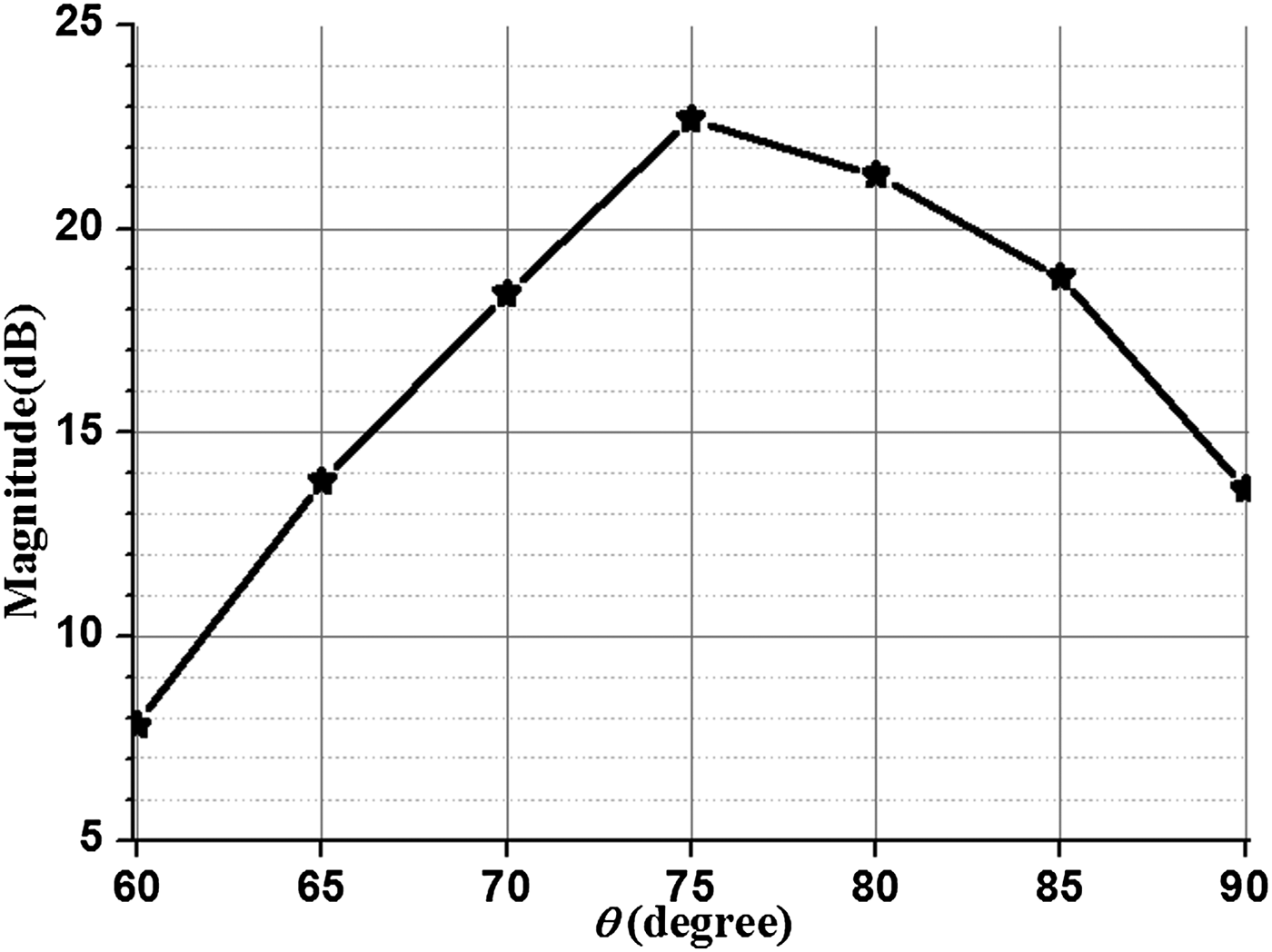
As an illustration, the measured gain G versus θ is presented in Fig. 10 for S = 1.5 m and F = 2 m.
Measured gain versus θ for the 80-groove array at 60 GHz.
Comparison of the received power at 60 GHz between the initial reference and the improved one with the array when θ = 75°, S = 1.5 m, and F = 2 m.
The maximum gain of 22.7 dB is obtained close to θ = 75°, which is consistent with the main beam position in Fig. 8. The small shift of the main beam towards θ = 90° may be explained by the larger value of F (compared with that used in Fig. 7), which provides a more uniform illumination to the reflector. As a better figure of merit, Fig. 11 compares the received power when Rx antenna is at θ = 75°, with and without the repeater.
The received power without repeater (red curve, initial reference from the first step) is very close to noise floor due to the use of directive horns in a NLOS configuration. After including the 80-groove repeater (black curve, second step of the measurement), the received signal reaches −55 dBm, which is fully compatible with classical receivers. In conclusion, Fig. 11 provides a clear demonstration of the array performance by showing that the signal is recovered, and the radio linkage in NLOS environment is re-established.
IV. CONCLUSION
This paper has investigated a planar reflector aiming at improving power transmission at 60 GHz in the typical NLOS scenario of a T-shaped corridor. The reflector consists of parallel grooves in a metallic plate, thus offering a quite simple and low-cost structure with low profile that could be easily deployed on the walls. By alternating two different heights for the groove elements, out-of-phase reflections are produced and wave cancellation at broadside is obtained. Moreover, by using λ 0/2 inter-element spacing, most power is transmitted parallel to the array surface to provide a quasi-endfire radiation. Due to the effect of the groove unitary pattern, the main beams are not exactly obtained at grazing angles. However, the observed angular shift of the beams from ±90° is supposed to be favorable for a correct illumination of the orthogonal branches of a T-shaped corridor. An 80-groove array has been fabricated and first measured in an anechoic chamber. Comparisons between the measured gain and the theoretical predication are in quite good agreement, and demonstrate the working principle. Then, measurements have been conducted in a configuration representing a practical NLOS environment. With the help of the reflecting array, the signal received at the Rx antenna is greatly improved at 60 GHz in the θ = 75° direction. This definitively demonstrates the capabilities of the array for the prescribed T-shaped corridor configuration.
Duo Wang was born in Chongqing, China, in 1986. He received the B.Sc. degree in Electronics and Information Science and Technology in 2008, and the M.S. degree in Radio Physics in 2011, from the University of Electronic Science and Technology of China, Chengdu, China; and a Ph.D. degree in Electronics and Telecommunication in 2015 from the National Institute of Applied Sciences de rennes (INSA de Rennes), France. His research interests include millimeter antennas and antenna arrays.
Raphaël Gillard obtained his Ph.D. degree in Electronics from INSA Rennes, France, in 1992. He first worked as a Research Engineer in the company IPSIS, France, developing a commercial MoM code for the simulation of microwave circuits and antennas. He joined INSA in 1993 as an Assistant Professor. He contributed to the development of an FDTD simulation code for antennas and to the experimentation of wavelet-based fast solvers. Since 2001, he has been a full Professor in the Antenna and Microwave Group (now Complex Radiating Systems team) since 2006. At the moment, his main research interests are computational electromagnetics and reflectarrays. Raphaël GILLARD has been involved in the European Antenna Centre of Excellence (ACE), as a member of both the Executive and Governing Boards of this network and co-leader of its Antenna Software Activity from 2004 to 2008. He is the member of several Scientific Committees and Review Boards and was co-chairman of the French URSI-B section.
Renaud Loison received the Ph.D. degree in Electronics from the National Institute of Applied Sciences (INSA), Rennes, France, in 2000. In 2008, he joined the Institute of Electronics and Telecommunications of Rennes (IETR), Rennes, France, as an Associate Professor. Since 2009, he has been a full Professor with the Complex Radiating Systems Group, IETR. His research interest concerns reflectarray and numerical method applied to the analysis and optimization of microwave circuits and antennas.