I. INTRODUCTION
Since 2002, WiFi listed and WiFi hotspot application has ignited widespread interest in wireless data transmission. People of the world began to believe and now prefer to use wireless communication because of the rapid progress in 4G transmission. So, with the vigorous development of the wireless communications industry, the quality of wireless communication services demands immense speed. The constant emphasis of wireless communication systems resides in performance improvement, and practices of perfecting antenna characteristics so that the overall system performance of communication can be much improved. As the printed and center-fed antenna is simple, stable, and easy-to-be-manufactured, it is already widely used in the wireless communications industry. The WiFi AP commonly uses the external printed antenna as the main antenna, and the frequency band of 802.11b/g/a/n/p/h applications are 2.4–2.483, 5.15–5.35, and 5.725–5.875 GHz. Webster [Reference Webster1] describes the traditional concepts on how to adjust the frequency band by changing the spacing between both ends of the dipole antenna pairs to generate 2.4 and 5 GHz dual-band. The concept of the new design printed inverted-F antenna (IFA), based on uniplanar compact electromagnetic band-gap (EBG) structure, is proposed in [Reference Elsheakh and Abdallah2]. This printed IFA with an L-load shaped over an artificial ground plane is designed as the main antenna to cover most wireless applications such as GSM, LTE, UMTS, Bluetooth, Wimax, and WLAN. The multi-band is created by means of an EBG structure that is used as a ground plane.
Su et al. in [Reference Su, Chen and Wong3] present a symmetrical dipole antenna, wherein symmetrical U-shaped slots are inserted into the symmetrical dipole arms to generate 2.4/5.2 GHz WLAN frequency bands. The antenna size of the FR4 substrate is 5 × 50 × 0.4 mm3 and its frequency bandwidths are 2290–2790 MHz (500 MHz) and 5140–5510 MHz (370 MHz). The design feature of the antenna in this method is simple and allows the antenna size to be very small, though high-frequency bandwidth for WiFi applications are slightly less. Zhang et al. in [Reference Zhang, Iskander, Langer and Mathews4] present an internal matched printed dipole antenna, which was fed at the middle of the center gap, and matched by changing the length and width of the arms of the dipole antenna to adjust the location and bandwidth of the frequency band; the matching network can be simplified to only one series inductor. The antenna size of FR4 substrate is 12 × 45 × 0.45 mm3 and the measured VSWR2:1 bandwidth in the 2.4 GHz band is 710 MHz, and the bandwidth in 5 GHz band is wider than 1 GHz. Kuo and Wong in [Reference Kuo and Wong5] present a novel and simple printed dual-band double-T monopole antenna. The antenna size of the FR4 substrate is 69.5 × 45 × 0.8 mm3 and the measured VSWR2:1 bandwidth in the 2.4 GHz band is 495 MHz, and the bandwidth in 5 GHz band is 210 MHz. The high-frequency bandwidth for WiFi applications is slightly less. Hwang et al. in [Reference Hwang, Moon, Kwak and Park6] proposed a printed compact dipole antenna for dual ISM band, the impedance bandwidth for 10 dB return loss is about 400 MHz at 2.4 GHz band and over 2300 MHz at 5 GHz band. The proposed antenna occupies a volume of 15 × 40 × 1 mm3. The measured radiation gains range from 1.20 to 1.41 dBi at 2.4 GHz band and from 2.25 to 3.44 dBi at 5 GHz band, respectively. Ávila-Navarro et al. in [Reference Ávila-Navarro, Carrasco and Reig7] present a novel Yagi-like, printed-dipole dual antenna for WiFi applications. The antenna size of FR4 substrate is 48.5 × 85.9 × 1.52 mm3 and the measured VSWR2:1 bandwidth in the 2.4 GHz band is 650 MHz, and the bandwidth in 5 GHz band is 800 MHz. The measured radiation peak gain is 2.2 dBi at 2.4 GHz band and 6.2 dBi at 5 GHz band, respectively. Zhang et al. in [Reference Zhang, Chu and Wang8] proposed a novel compact printed dual-band dipole antenna with an integrated wideband balun. With the integrated balun, the proposed antenna yields an impedance bandwidth of 2.38–2.65 and 4.95–6.35 GHz with return loss of less than −10 dB, while retaining a compact size of 30 × 25 × 0.8 mm3. The measured gain varies from 1.5 to 2.25 dB across the frequency bands from 2.38 to 2.65 GHz, and 1.75 to 3.20 dB across the bands from 5.0 to 6.0 GHz. Zhang et al. in [Reference Zhang, Li, Liu, Shi and Wang9] proposed a novel printed dipole antenna with low cross-polarization levels for WLAN applications, using four L-shaped slots and a unique tapered structure, which is fabricated on a substrate having 1 mm thickness and relative dielectric constant of 2.65 with an overall size of 22 × 44 mm2. The measured bandwidth (S 11 < −10 dB) is 650 MHz in the lower band, whereas in the upper band it is 2.9 GHz. The peak gain at 2.4 GHz band is 2.38 dBi, and for the 5.5 GHz band, the peak gain is 4.57 dBi. Chang and Weng in [Reference Chang and Weng10] proposed a dual-band printed dipole slot antenna with two-folded slots and a T-shape microstrip-fed line for WLAN applications. The antenna has a compact size of 40.0 × 15.0 × 1.6 mm3. Kaur et al. in [Reference Kaur, Khanna and Kartikeyan11] proposed a novel multistrip monopole antenna fed by a cross-shaped stripline comprising one vertical and two horizontal strips. The designed antenna has a small overall size of 20 × 30 × 1.5 mm3. The measured impedance bandwidths are about 200 MHz (2.3–2.54 GHz) and 590 MHz (5.26–5.85 GHz). The peak antenna gain value is 3 dBi at 2.4 GHz and 4.2 dBi at 5 GHz, respectively. In [Reference Tsai and Tsai12], we presented the architecture and simulation results of this novel and compact antenna. We further present the fabricated antenna and measured results to prove the simulation results in this paper.
In this paper, we present a novel antenna structure to generate a dual band for WiFi applications. This printed antenna is suitable for the AP and embeds mobile devices applications. Its oscillation points are at 2.4/5.4 GHz and the return losses are about16 and 17 dB, respectively. The measured frequency bandwidth defined for 10-dB reflection coefficient of this antenna is 2.3–2.61 GHz at 2 GHz, and the high frequency bandwidth is 4.82–5.84 GHz at 5 GHz, which meets the requirements for applications in global WiFi communications. This printed antenna size is 7 × 45.9 × 1 mm3. The design, analysis, and measured results of antenna parameters of the bandwidth, current distributions, and radiation patterns will be further proposed in the following.
II. ANTENNA DESIGN AND PARAMETERS ANALYSIS
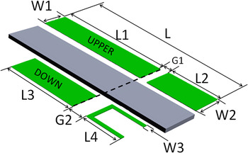
In this paper, a novel and compact antenna is presented, and its structure is shown in Fig. 1. The main body of the antenna consists of the ground arm L 1 and the radiator arm L 2 placed on the upper side of the substrate. The label G 1 represents the gate between L 1 and L 2 and is center-fed by the 50 Ω coaxial cable. The parasitic part consists of the metal of length L 3 and the U-shaped microstrip line L 4 placed on the underside of the substrate. The substrate is the FR4 epoxy material with a relative dielectric constant 4.4 of thickness 1 mm.
The architecture of the proposed antenna.

In the architecture in Fig. 1, the parameters are L 1, L 2, G 1, L 3, L 4, G 2, W 2, W 3, etc. In this design, the lengths of L 1 and L 2 are assumed to be λ/4 of the lower (2.45 GHz) and higher (5.3 GHz) band, respectively. The required dual-band feature of the antenna can be tuned by the gap width. The parasitic metal length of L 3 is assumed to be the square root of L 1 and L 2. The length of U-matched line L 4 needs to be tuned by the requirement of the bandwidth and the gain value. These antenna parameters are simulated by the software HFSS.
A) Varying lengths of L 1 and L 2
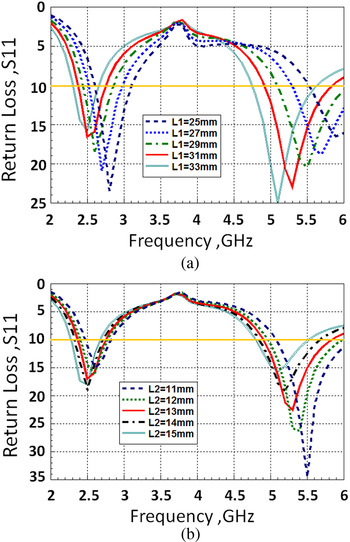
Figure 2(a) demonstrates the simulated return losses related to different lengths of L 1 = 25, 27, 29, 31, and 33 mm. The changing of length L 1 affects the bandwidth of the low- and high-frequency bands simultaneously. While the length of L 1 is reduced from 33 to 25 mm, the corresponding low-frequency band increases from 350 to 500 MHz, while the corresponding high-frequency band increases from 860 to 1140 MHz. For achieving the requirements of the WiFi bandwidth, we select L 1 = 31 mm which nearly corresponds to λ/4 of the oscillation point 2.5 GHz. During the simulation procedure of L 1, other parameters are kept constant.
Simulated return losses under changing the length of (a) L 1 and (b) L 2.

Figure 2(b) demonstrates the simulated return losses related to the different length of L 2 = 15, 14, 13, 12, and 11 mm. When the length of L 2 is reduced to 11 mm from 15 mm, the corresponding low-frequency band becomes larger and then reduces; the bandwidth increases from 339 to 390 MHz and the falls to 350 MHz, the corresponding high-frequency bandwidth increases from 700 to 1060 MHz. The variation in length of L 2 mainly affects the bandwidth at 5 GHz. For achieving the requirements of WiFi bandwidth, we select L 2 = 13 mm, which is nearly correspond to λ/4 of the oscillation point of 5.3 GHz. During the simulation procedure of L 2, other parameters are kept constant.
B) Varying the length of L 3 and L 4
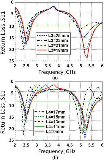
Figure 3(a) demonstrates the simulated return losses related to the different lengths of L 3 = 25, 23, 21, and 19 mm. The change of L 3 does not affect the bandwidth of the low-frequency band but shifts the oscillation point slightly. The change of L 3 has a larger effect on the high-frequency band. While the length of L 3 is reduced from 25 to 19 mm, the corresponding bandwidth of high frequency increases from 400 to 930 MHz. For achieving the requirements of the global WiFi bandwidth, we select L 3 = 19 mm, which is approximately the square root of L 1 and L 2, to enhance the bandwidth at 5 GHz. During the simulation procedure of L 1, other parameters are kept constant.
Simulated return losses under changing the length of (a) L 3 and (b) L 4.

Figure 3(b) demonstrates the simulated return losses related to the different lengths of L 4 = 17, 15, 13, 11, and 9 mm. The change of L 4 shifts the oscillation points at 2 and 5 GHz simultaneously. Besides while the length of L 3 is shortened from 17 to 9 mm, the corresponding bandwidth of high-frequency increases from 400 to 930 MHz. For achieving the requirements of the global WiFi bandwidth, we select L 4 = 9 mm for this parameter analysis. During the simulation procedure of L 1, other parameters are kept constant.
C) Varying the width of G 1 and W 2
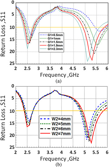
Figure 4(a) demonstrates the simulated return losses related to the different widths of G 1 = 0.5, 1, 1.5, 1.9, and 2.3 mm. Changing the width G 1 affects the bandwidth of the low- and high-frequency band simultaneously. When the length of G 1 becomes larger, the low-frequency bandwidth increases to 370 MHz, and the high-frequency bandwidth increases from 820 to 970 MHz. We select G 1 = 1.9 mm to be the optimum. During the simulation procedure of G 1, the initial positions of L 2 and U-line need to be changed simultaneously.
Simulated return losses under changing of (a) gap width G 1 and (b) width of W 2.

Figure 4(b) demonstrates the simulated return losses related to the different widths of W 2 = 4, 5, 6, and 7 mm. Changing the width W 2 has no effect on the bandwidth of the low, but has a little effect on the bandwidth of high frequency. We select W 2 = 7 mm to be the optimum. During the simulation procedure of W 2, other parameters are kept constant.
III. RESULTS AND DISCUSSION
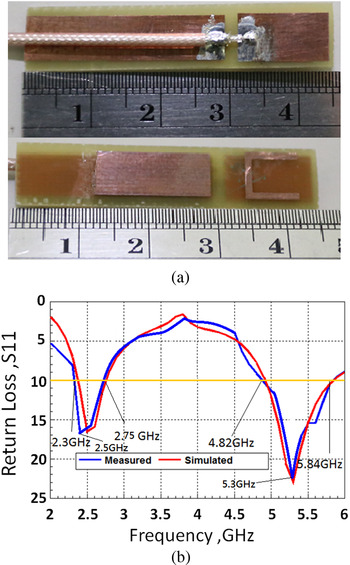
Based on the simulation results of various parameters, the final size of antenna are L 1 = 31 mm, L 2 = 13 mm, L 3 = 19 mm, L 4 = 9 mm, G 1 = 1.9 mm, G 2 = 4 mm, W 1 = 6.5 mm, W 2 = 7 mm, W 3 = 1 mm, L = 45.9 mm, and H = 1 mm. This antenna is fabricated on an FR4 substrate with a relative dielectric constant 4.4 of thickness H = 1 mm, and the antenna size is 7 × 45.9 mm2, which is measured by the R&S ZVL 9 kHz–6 GHz network analyzer. The fabricated antenna is shown in Fig. 5(a) and the measured bandwidths under return loss 10 dB are 2.37–2.75 GHz (380 MHz, 14.8%) and 4.87–5.84 GHz (970 MHz, 18.1%) as shown in Fig. 5(b). This antenna bandwidth can meet the requirements for applications in global WiFi communication. The simulation and measured results of the bandwidth match well.
(a) Photograph and (b) measured results of the fabricated filter.

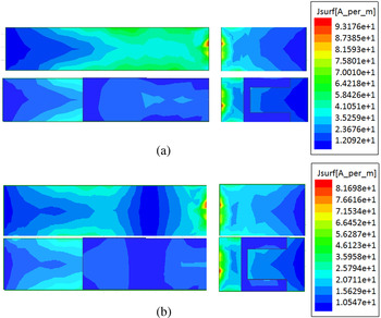
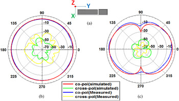
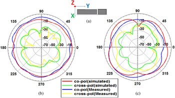
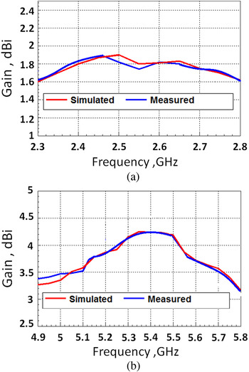
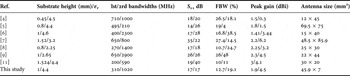
Figure 6 demonstrates the current distribution of 2.45 and 5.4 GHz. By the current distribution of 2.45 GHz, we mean that the maximum current is distributed over the long arm L 1 and the gap G 1, L 2, which can predict the near-omni-directional pattern of 2.45 GHz as shown in Fig. 7. Figures 7 and 8 demonstrate that the measured and simulated patterns are close to each other. Figure 9 demonstrates that the simulated and measured gain values of low frequency are stable between 1.55 and 1.95 dBi, the gain value of high frequency is stable between 3.05 and 3.51 dBi, and they are very close. A comparison of the proposed antenna with other reported dual-band antenna is summarized in Table 1. Following the results in Table 1, our presented antenna has the smallest size, a better gain value, and is a suitable dual wide bandwidth antenna.
Current distributions of (a) 2.45 GHz and (b) 5.4 GHz.

(a) Antenna position, (b) H-plane radiation pattern and (c) E-plane radiation pattern of 2.45 GHz.

(a) Antenna position, (b) H-plane radiation pattern and (c) E-plane radiation pattern of 5.3 GHz.

Gain values of (a) 2.3–2.8 GHz and (b) 4.9–5.8 GHz.

Comparison of the proposed antenna with other reported dual-band antenna.

IV. CONCLUSION
In this paper, a novel and compact printed antenna is presented to meet the requirements of WiFi dual-band communications. The size of this printed antenna is 7 × 45.9 × 1 mm3; it is suitable for the WiFi AP and mobile embedded antenna application. Bandwidths of this antenna are 2.3–2.61 GHz (310 MHz, 12.7%) and 4.82–5.84 GHz (1020 MHz, 19.1%), which meet the requirements for applications in worldwide WiFi communications. This antenna has an omni-directional radiation pattern and a stable gain value between 1.55 and 1.95 dBi at 2.4 GHz and between 3.05 and 3.51 dBi at 5 GHz.
 Churng-Jou Tsai was born in Taipei, Taiwan on October 28, 1978. He received his B.S. degree in electrical engineering at the Chung Yuan Christian University in Taiwan in 1982, his M.S. degree in Electrical Engineering at the National Cheng Kung University in Taiwan in 1989, and his Ph.D. degree in Electrical Engineering from the National Cheng Kung University in Taiwan in 1994. He is currently Associate Professor and the Director of the Department of Computer and Communication at the Kun Shan University in Taiwan. His research interests include antenna design, wireless communication, smart living and adaptive signal processing. His work “Smart Emergency Indicator System” won a gold medal of the General Assembly, Geneva City Hall Fire Class Special Award and Iran Invention Association Special Award at the 2012 Exhibition of Inventions in Geneva, Switzerland. His work “The Simulated Electronic Blowgun” won a gold medal of the General Assembly in 2013 Seoul, South Korea Invention Exhibition.
 Bo-Yuan Tsai received his B.S. degree from the Department of Computer and Communication at the Kun Shan University in Taiwan in 2010. He is currently studying for his M.S. at the Department of Computer and Communication, Kun Shan University. His research interests include antenna design and RF passive component design.