I. INTRODUCTION
Phase shifters are vital microwave components in which the phase component of an electromagnetic wave in a specific frequency band can be shifted or controlled when propagating through it. Analog phase shifters provide linear or continuous phase variations. Left-handed transmission lines are artificial structures that act as a medium with negative values of permittivity (ε) and permeability (μ) [Reference Sajin, Praveen, Habiba and Rao1] at the operating frequencies. Owing to the negative values of ε and μ, backward-wave propagation results [Reference Baena2], which exhibit phase-leading properties. Complementary split-ring resonator (CSRR) exhibits this property of double-negative media and therefore development and implementation of CSRR for microwave components such as phase shifters [Reference Sajin, Praveen, Habiba and Rao1], couplers, and filters [Reference Velez, Aznar, Bonache, Velazquez-Ahumada, Martel and Martin3, Reference Liu, Shu, Zeng and Chang4] have been an area of interest in recent years, owing to their attractive properties such as backward-wave propagation, circuit size miniaturization, low cost, and low loss [Reference Baena2, Reference Liu, Shu, Zeng and Chang4].
This paper presents an analog, reciprocal dual-frequency phase shifter with a pair of symmetric CSRR, grooved vertically and placed in parallel to each other in the ground plane. This phase shifter operates at two different frequency bands and the phase shifts at the required frequencies viz. 2.4 and 5.4 GHz are quantified by comparing with the phase obtained by the ideal transmission line having the finite ground plane. The reflection coefficient (S 11), the transmission coefficient (S 21), and the transmission phase (arg S 21) are provided to study the functionality of the prototype design.
II. DESIGN SPECIFICATIONS
A simple 50 Ω transmission line is designed on an FR4 substrate with dielectric constant 4.3, loss tangent 0.025, and substrate thickness 1.6 mm. The dimension of this transmission line is a = b = 18 mm and c = 3 mm as given in Fig. 1(a). This phase shifter line depicts a 90° delay line of length λ g /4 at 2.4 GHz. This line is used as a basic line to compare the phase shifts, which would be obtained when CSRR are used.
(a) Reference line configuration. (b) Transmission line loaded with a CSRR in the ground plane.

CSRR structures are generally derived from the ring resonator structures, which are analytically proposed with wavenumbers using Bessel function as in (1).
 $${K_{nml}} = \displaystyle{{{x_{nm0}}} \over a} = \displaystyle{{{P_{nm}}} \over a},$$
where P nm is the root of transcendal equation having derivatives with respect to argument of Bessel function of first kind and order n, and a is the inner radius of the ring resonator.
The resonant frequency can be calculated from the resonance wavenumber as in (2).
 $${f_{nm0}} = \displaystyle{{c{K_{nm0}}} \over {2\pi \sqrt {{\varepsilon _r}}}}. $$
The normalized ring width for the desired mode of propagation is taken from the (w/r) ratio, where w is the width between inner and outer radius of the ring resonator and r is the radial distance between the center of circular ring and intermediate radius of the ring. To obtain the transmission characteristics of the proposed phase shifter model over the bandwidth, the normalized propagation constant is also analyzed along with the normalized ring width. The normalized propagation constant is taken by multiplying the phase constant (k = 2πf/c) and the radial distance between the center of the circular ring and the intermediate radius of the ring (r).
Figure 1(b) gives a simple transmission line loaded with a CSRR on the ground plane. This configuration exhibits stopband characteristics [Reference Falcone, Lopetegi, Baena, Marqués, Martín and Sorolla5] at a single-frequency band (industrial, scientific and medical (ISM) band) as given in Fig. 2.
Transmission and reflection characteristics of a basic transmission line and a CSRR-loaded transmission line.

The transmission and reflection characteristics of the simple transmission line and the CSRR-loaded transmission line are given in Fig. 2.
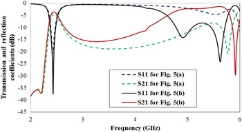
In order to improvise the stopband characteristics in the ISM band, the transmission line is loaded with another CSRR, placed in parallel with the previous one as given in Fig. 3. The transmission and reflection characteristics of this configuration are given in Fig. 4. It can be noted that another band of operation is introduced corresponding to the length of the transmission line in between two CSRRs. In order to convert the stopband characteristics of the transmission line to passband characteristics, gaps are etched on the transmission line directly above the CSRR. The gaps in the line introduce capacitive effect which is optimized for impedance matching by introducing stubs [Reference Sajin, Praveen, Habiba and Rao1], as in Fig. 5(a).
Simple transmission line loaded with a pair of CSRR on the ground plane.

Stopband characteristics exhibited by a transmission line loaded with a pair of CSRR.

(a) Configuration to convert stopband to passband characteristics and for impedence matching. (b) Modification in transmission line for shifting the band of operation.

The stopband to passband conversion is depicted in Fig. 6. The part of the transmission line in between the stubs is modified as in Fig. 5(b), to improve transmission in the desired bands of operation and to shift the second band of operation toward lower frequency, so that it operates in the wireless local area network (WLAN) band as given in Fig. 6.

Another stub is added in the transmission line on the signal plane as in Fig. 7, in order to enhance the reflection characteristics and bandwidth of the second band. Figure 7 gives the proposed prototype with dimension a = b = 18 mm. The design specifications of the proposed line and the CSRR used are given in Figs 8(a) and 8(b), respectively.
Proposed prototype.

(a) Transmission line optimized for use with CSRR. (b) Pair of CSRR in the ground plane.

Operating frequencies can be adjusted by varying the circumference of the CSRR and the distance between the two CSRR. From the equivalent model in [Reference Liu, Shu, Zeng and Chang4], the parameters of the CSRR can be adjusted to control the bandwidth of operation and to obtain the desired phase delay. The phase delay of the ISM band is controlled by optimizing the width of the gap in between the two concentric rings of the CSRR and the variation of phase as a function of frequency is given in Fig. 9. Similarly, the phase delay of the WLAN band is controlled by varying the layout parameter e, given in Fig. 8(a), and the variation of phase is given in Fig. 10. The design presented in this paper is optimized for operation at ISM band (2.38–2.49 GHz) and WLAN band (5–5.8 GHz), considering the impedance bandwidth, providing a phase of 180° at 2.4 GHz and 90° at 5.4 GHz.
Variation of phase, with respect to the width of the gap in the CSRR, in the ISM band as a function of frequency.

Variation of phase in the WLAN band, with respect to the layout parameter e, as a function of frequency.

The dimensions of the transmission line as per Fig. 8(a) are a = 18 mm, b = 8 mm, c = 1 mm, d = 1.7 mm, e = 1.85 mm, f = 3.45 mm, g = 2.5 mm, and h = 3 mm. The dimensions of the CSRR as per Fig. 8(b) are i = 10.3 mm, j = 11.3 mm, k = 4.9 mm, l = 0.2 mm, m = 0.3 mm, n = 5.3 mm, o = 2.5 mm, and p = 0.3 mm.
III. RESULTS AND DISCUSSIONS
The prototype is fabricated and experimentally validated. Figure 11 shows the fabricated conventional microstrip line with finite ground and the proposed prototype with the rear view showing the implementation of CSRR. The reflection coefficient, transmission coefficients, and the transmission phase are measured. From the simulated and measured scattering parameters in Fig. 12, it is evident that the designed prototype operates at ISM and WLAN bands. The discrepancy between the simulated and measured results is attributed to fabrication tolerance and imperfections in soldering the connectors due to small size of the prototype. Cable loss also accounts for the discrepancy. The results also show a higher insertion loss due to residual losses.
Fabricated prototypes. (a) Reference microstrip transmission line. (b) Ground plane of reference microstrip transmission line. (c) Signal plane of the proposed prototype. (d) Ground plane with CSRR.

Reflection and transmission coefficients versus frequency.

In Fig. 13, the simulated and measured transmission phases as a function of frequency are given, and it is evident that the designed prototype gives a 179° phase at 2.4 GHz and a phase of 89° at 5.4 GHz. From the results obtained, it can also be given that the extra phase shifts given by the proposed prototype, when compared with a conventional λ g /4 line corresponding to 2.4 GHz, are 90° at 2.4 GHz and 60° at 5.4 GHz. The designed prototype accounts for 180° phase shift at 2.4 GHz. The ideal transmission line given in Fig. 1 would require twice the length to give the same phase shift; therefore the proposed prototype accounts for 50% size reduction for a 2.4 GHz delay line which is given in Fig. 1. The prototype also accounts for 100% elimination of another transmission line of length λ g /4 corresponding to 5.4 GHz.
Transmission phase versus frequency.

IV. CONCLUSION
A dual-frequency phase shifter with a pair of CSRR in the ground plane is presented. The prototype is compared with a conventional λ g /4 line providing a phase of 90° at 2.4 GHz. It gives a delay of 180° at 2.4 GHz which is twice to that provided by the conventional line and this accounts for 50% size miniaturization. Another band of operation is incorporated, where a delay of 90° is obtained at 5.4 GHz. This would require another transmission line of length λ g /4 corresponding to 5.4 GHz. This can be used in beam steering application where dual-frequency operations are employed.
 Indhumathi Kulandhaisamy is currently pursuing her Ph.D. degree in the Department of Electronics and Communication Engineering, College of Engineering Guindy, Anna University, Chennai, India. Her area of interest includes Planar Microwave Devices.
 Dinesh Babu Rajendran is currently pursuing his Masters degree in Engineering in Communication Systems in College of Engineering Guindy, Anna University, Chennai, India. His areas of interest include Microwave Devices and Antenna Design.
 Malathi Kanagasabai is currently serving as an Associate Professor in the Department of Electronics and Communication Engineering, College of Engineering Guindy, Anna University, Chennai, India. Her research interests include Microwave Communication, Planar Transmission Lines, Planar Antennas, Signal Integrity Analysis in High-Speed Systems, etc.
 Balaji Moorthy is currently pursuing his Masters degree in Engineering in Communication Systems in College of Engineering Guindy, Anna University, Chennai, India. His areas of interest include Antenna Design and Frequency Selective Surfaces.
 Jithila V. George is currently pursuing her Masters degree in Engineering in Communication Systems, in College of Engineering Guindy, Anna University, Chennai, India. Her areas of interest include Microwave Devices and Design of Vivaldi Antennas.
 Livya Lawrance is currently pursuing her Masters degree in Engineering in Communication Systems, in College of Engineering Guindy, Anna University, Chennai, India. Her areas of interest include Microwave Devices, Design of Grid Array Antennas, and Automotive Antennas.