Introduction
Polarization of an electromagnetic (EM) wave gives information about the electric field oscillating direction in the plane perpendicular to the direction of propagation [Reference Shukoor and Dey1]. Manipulating wave polarization has a significant role in applications like RCS reduction, sensing, and imaging from microwave [Reference Shukoor, Dey and Dey2] to THz regime [Reference Saju, Yohannan, Mamman, Kunju, Shukoor and Dev3]. Generally, the Birefringence effect [Reference Danner, Tyc and Leonhardt4], circular dichroism [Reference Cheng, Tian, Li, Deng, Yu and Chen5], and molecular level chirality [Reference Huck, Jager, de Lange and Feringa6] occur in naturally occurring materials and are responsible for polarization modulation. But these crystals suffer from huge power losses and greater thickness, limiting their usage in real-time sub-miniaturized applications [Reference Zheng, Guo and Ding7].
Frequency selective surfaces (FSSs) are the 2D-spatial filters that possess advantages like planar nature, low profile, and fabrication ease [Reference Shukoor and Dey8]. The advancement of FSS technology has drawn researchers' attention in modulating the EM wave features like amplitude, phase, and polarization states using FSS [Reference Shukoor and Dey9]. Controlling the propagation states of EM waves has been reported in reflection and transmission modes over the EM spectrum [Reference Shukoor and Dey10]. A compact, high-efficiency microwave linear-cross polarizer based on square split rings is demonstrated [Reference Shukoor and Dey9], with unity cross-pol reflectance from 8.2 to 23 GHz. Huang et al. proposed an ultrathin dual-band reflective polarizer that performs linear-cross conversion in frequency ranges 4.40–5.30 GHz and 9.45–13.60 GHz [Reference Huang, Yang, Zhang and Luo11]. A 45° oriented H-shaped linear-cross reflective polarizer is demonstrated for K- and Ka-bands (17.97–40.23 GHz) with minimal bandwidth reduction at higher oblique angles [Reference Shukoor, Dey, Koul, Poddar and Rohde12]. This design can also maintain handedness to the circularly polarized wave. Asymmetric meanderline structures are also utilized for broadband linear-cross conversion [Reference Shukoor, Dey and Koul13].
For circular polarization conversion, Jerusalem cross-based reflective linear-circular polarizer with an axial ratio (AR) ≤ 1 dB bandwidth of 15% is proposed in X-band [Reference Wang, Kong, Ma and Cui14]. Multiband reflective type multi-polarization conversion is demonstrated by a double L-type resonator of different dimensions [Reference Mao, Yang, He, Zheng and Zhou15]. From 11.3 to 20.2 GHz, a flexible broadband linear-cross reflective polarizer with an average polarization conversion ratio (PCR) of 85% is designed [Reference Wang, Kong, Yan, Xu, Liu, Mo and Liu16]. Active devices like p-i-n, varactor diodes, and their integration with metasurfaces have also been illustrated for multifunctional characteristics [Reference Yang, Kou, Yu, Long, Yuan, Ding and Zhang17]. The linear-circular invertibility is also achieved using an ultrathin broadband single-layer polarization converter in a near-infrared regime [Reference Li, Liu, Cheng, Chen and Tian18]. However, few studies have focused on converting a linear to a cross and circular polarization simultaneously across wideband.
This work proposes a novel single-layered dual-polarized multiband reflective type metasurface enabled linear-circular and linear-cross polarizer. The design of the unit cell and its simulation results are detailed in section “Design of polarizer's unit cell”. Surface current distributions in section “Analysis and discussion” elaborate the analysis for the multi-conversion. The measured results obtained from the free-space measurement technique are compared with the simulated one in section “Fabrication and measurement setup”. Good matching is observed between those two, and finally, the conclusion has been drawn in “Conclusion” section.
Design of polarizer's unit cell
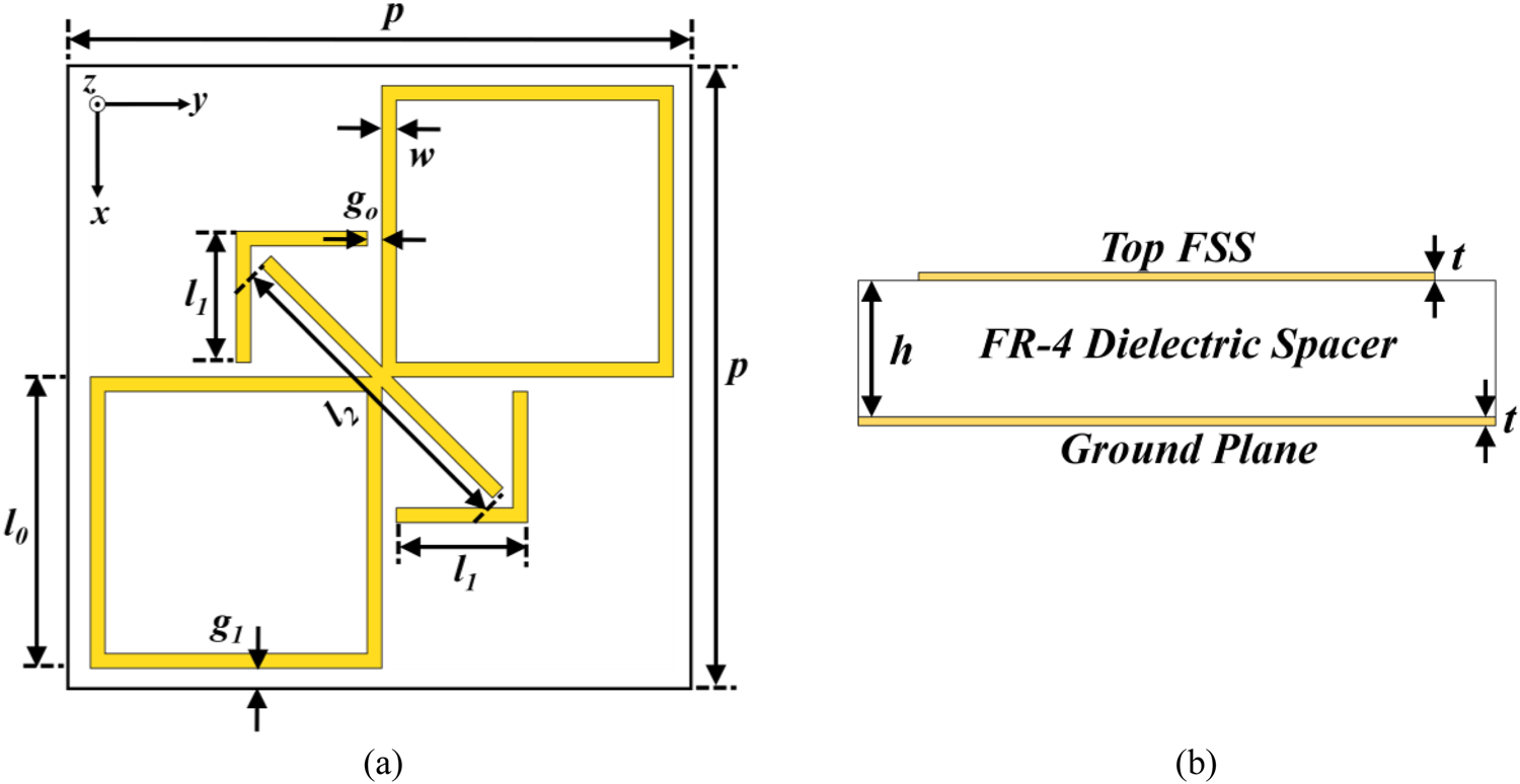
The proposed reflective polarizer consists of an eight-obsessed square loop as top FSS and orthogonally linked arrow, as shown in Fig. 1(a). The FSS is printed on the top of a commercially available FR-4 substrate with relative permittivity ɛr = 4.4, and loss-tangent tan δ = 0.02, which is metal-backed on the other side. Copper film with conductivity σ = 5.8 × 10⁷ S/m is used as metallic layer. The unit cell dimensions are optimized in a finite element method (FEM) based EM solver ANSYS HFSS with appropriate periodic boundary conditions. The final parameters are: p = 7.3 mm, l 0 = 3.52 mm, l 1 = 1.584 mm, l 2 = 3.96 mm, w = 0.176 mm, g 0 = 0.176 mm, and g 1 = 0.13 mm, h = 2.4 mm, and t = 0.035 mm, as depicted in Fig. 1.
(a) Top view, and (b) side view of the proposed reflective polarizer.

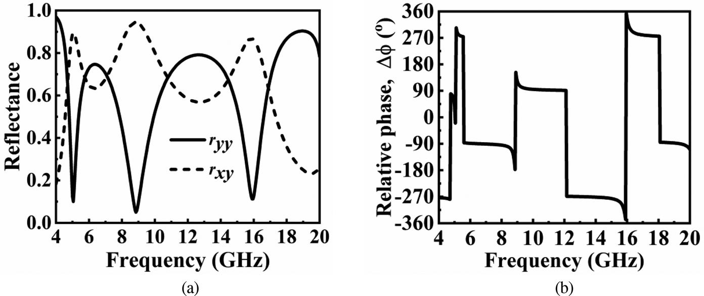
For a y-polarized wave incidence on the reflective polarizer, the co-pol (r yy = |E yr|/|E yi|), and cross-pol (r xy = |E xr|/|E yi|) reflectances are defined due to the asymmetry that exists. Here, E x and E y represent electric field oscillations along the x- and y-axes, respectively, with indices i and r denoting incident and reflected components. The simulated magnitudes and relative phase of the reflectances are shown in Fig. 2, and it seems clear that r yy approaches zero at three frequencies, 5.05, 8.85, and 15.95 GHz, while r xy reaches near-unity (see Fig. 2(a)). The term PCR determines the efficiency of any reflective linear-cross polarizer, expressed as

Simulated (a) magnitudes and (b) phases of the co-pol and cross-pol reflectances of the proposed polarizer.

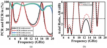
The PCR is above 90% from 4.92 to 5.18 GHz (C-band), 8.32 to 9.41 GHz (X-band), and 15.56 to 16.25 GHz (Ku-band), as shown in Fig. 3(a). In addition, the amount of energy getting dissipated in the substrate during the multiple reflections between the FSS and ground is estimated by energy conversion ratio (ECR), $ECR = r_{xy}^2 + r_{yy}^2$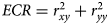 . The remaining energy is wasted via substrate losses, with almost 90% of incident energy reflected (see Fig. 3(a)). Besides linear-cross conversion, it also demonstrates linear-circular conversion. The circular polarization efficiency is calculated from the axial ratio (AR), calculated as in [Reference Li, Liu, Cheng, Chen and Tian18],


Simulated (a) PCR, ECR, and (b) AR (dB) of the proposed polarizer with and without arrow dipole.

Here, the term schi (χ) represents the shape of the polarization ellipse. The simulated AR is ≤3 dB over the ranges 4.61–4.71 GHz (C-band), 5.44–7.68 GHz (C-band), 10.13–14.98 GHz (X, Ku-band), and 16.68–17.19 GHz (Ku-band), as shown in Fig. 3(b).
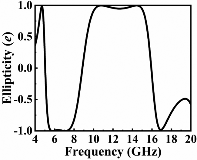
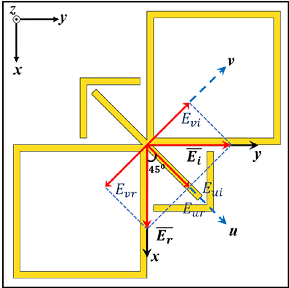
Since polarizer designs work based on the multiple plasmonic resonances, and three plasmonic resonances are dominant for the proposed design. The first resonance depends on the outer periphery of the figure of eight loops in the v-axis direction. The second resonance mainly depends on the substrate parameters like relative permittivity and thickness concerning ground, and the third resonance depends on the dimensions of the figure-of-eight loop along the u-axis direction (see Fig. 6). The PCR, ECR, and AR (dB) performance with and without arrow dipole is given in Fig. 3. For the design optimization for better performance, it is necessary to shift the higher resonance to the lower side by coupling along the u-axis direction to achieve a good AR bandwidth ≤3 dB. The arrow-shaped dipole is included in the proposed polarizer with square loops. The term ellipticity (e) can be used to describe the switching of circular rotation in successive bands, expressed as

The ellipticity range is varied from −1 (right-hand circular polarized, RHCP) to +1 (left-hand circular polarized, LHCP), as shown in Fig. 4. The handedness of circular rotation is sensitive to the relative phase (Δϕ) between co- and cross-pol reflectances, as in Fig. 2(b). This design is dual-polarized; the circular polarization's handedness will change if the y-polarized incidence is replaced with the x-polarized.
Simulated ellipticity (e) of the proposed reflective polarizer.

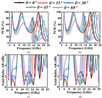
Since the incoming wave on the metasurface is not always normal in practical scenarios, it is necessary to investigate the performance variation with the angle of incidence for both the transverse electric (TE) and transverse magnetic (TM) modes. The PCR and AR variations for different angles (0° to 60° in steps of 15°) are depicted in Fig. 5. If the incident angle varies, it is trivial that the input surface impedance seen by the EM wave is different for different incident angles and modes. For the proposed design, it is observed that the response is almost stable up to 45° (see Fig. 5), and performance degrades due to grating lobes at higher oblique angles and weak field couplings. Although PCR solely considers reflectance magnitudes, the behavior of PCR at various oblique angles is well explained by reflectance phases. PCR bandwidth is reduced as the angle of incidence is moved away from the normal. The cross-pol component (r xy) has nearly unchanged amplitude and phase, whereas the co-pol reflectance has a significant angle of incidence dependence. The additional path between the metasurface and the ground influences the phase of co-pol reflectance significantly, creating a phase difference compared to normal incidence calculated by Bragg's diffraction [Reference Shukoor, Dey, Koul, Poddar and Rohde12].

Simulated PCR for the (a) TE, (b) TM, and AR (dB) for the (c) TE and (d) TM modes for different elevation angles (θ).

Here, θ is angle made by the incident ray with reference to polarizer normal, k is the wavevector in the dielectric medium. The reason behind the multiband multi-polarization conversion is analyzed in later sections.
Analysis and discussion
Analysis using transfer matrix method (TMM)
To acquire a true understanding of the physical mechanism involved in the polarization conversion, two orthogonal axes, u- and v-, are specified at 45° counterclockwise to the x–y axes (see Fig. 6). The incident electric field for a wave traveling along the negative z-axis is expressed as $\overrightarrow {E_i} = ( E_i^u \tilde{u} + E_i^v \tilde{v}) e^{jkz}$ , where $E_i^u$
 and $E_i^v$
 are the components along u- and v-axes, respectively. From the TMM technique [Reference Shukoor, Dey, Koul, Poddar and Rohde12], the reflected field components can be written as

Schematic view of the proposed reflective polarizer unit cell for uv-analysis.

The influence of cross-pol reflectance is very low and ignored since the unit cell design is symmetric along uv-axes. Then the reflected field component can be expressed as

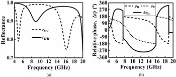
The simulated magnitudes and phases are depicted in Figs 7(a) and 7(b), respectively. The magnitudes of r uu and r vv are almost unity over the band, with a tiny dip at frequencies 4.95, 9.05, and 16.15 GHz (see Fig. 7(a)). The eigenmodes at 4.95 and 16.15 GHz are stronger (have a higher Q-factor) than the mode at 9.05 GHz. If the substrate loss is ignored, $r_{uu} = e^{j\varphi _u}$ , $r_{vv} = e^{j\varphi _v}$
 , and Δφ = φu − φv are obtained [Reference Lin, Guo, Lv, Wu, Ma, Liu and Wang19]. Different combinations of magnitudes and phases with the conditions for possible polarization conversions are summarized in Table 1.
Simulated (a) magnitudes of ruu, rvv, and (b) relative phase (Δϕuv).

Summary of polarization conversion for different relative phases (Δφ) and magnitudes (r uu and r vv)

Surface current distribution analysis
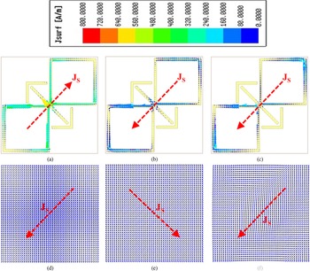
Surface current patterns of the polarizer's metallic portion are investigated to better understand the physical phenomena behind polarization conversion. At resonant frequencies, 5.05, 8.85, and 15.95 GHz, the current profiles for the top FSS and ground are depicted in Fig. 8. The symmetric and asymmetric linkage of incident EM fields induces plasmonic resonances, which may be electric or magnetic. From Fig. 8, the induced surface currents are antiparallel for the top FSS and ground plane at 5.05 and 8.85 GHz resembling the magnetic or dielectric resonance. In contrast, the currents are parallel for the 15.95 GHz case, resulting in electric resonances [Reference Shukoor and Dey9].
Surface current distributions of top FSS at (a) 5.05 GHz, (b) 8.85 GHz, (c) 15.95 GHz, and for the ground at (d) 5.05 GHz, (e) 8.85 GHz, (f) 15.95 GHz.

Fabrication and measurement setup
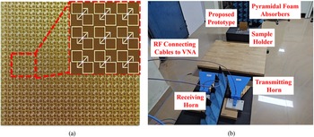
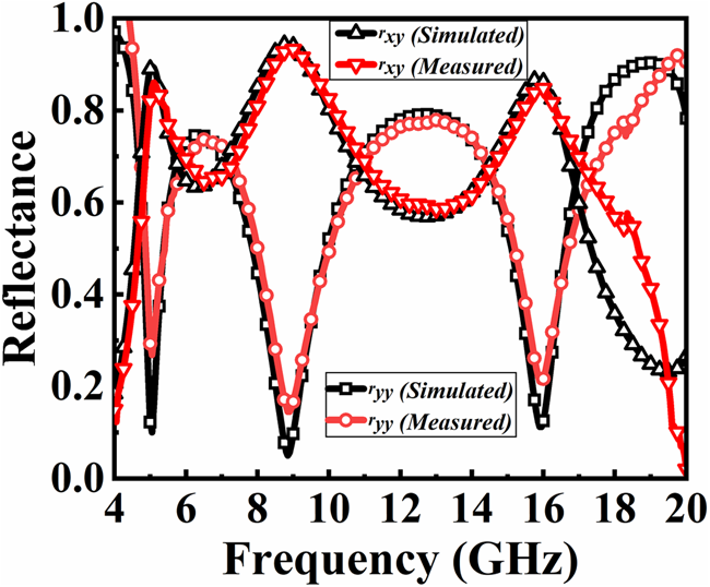
For the experimental verification, a 20 × 20 array (146 mm × 146 mm) of the proposed prototype is fabricated using traditional printed circuit board (PCB) technology, as shown in Fig. 9(a). The top FSS was printed on a thin 2.4 mm grounded FR-4 substrate. The free-space measurement technique is adopted for the reflection properties extraction of the sample [Reference Shukoor, Dey, Koul, Poddar and Rohde12], as depicted in Fig. 9(b). Two horn antennas (800 MHz–18 GHz) for the transmission and reception were connected to Keysight Power Network Analyzer (PNA) N5224B. The calibration of the PNA is done with the perfect electric conductor (PEC) sheet having the same dimension as the prototype. The measured reflectance (co-pol and cross-pol) is compared with the simulated one, and good matching is observed (see Fig. 10). The measured PCR and AR (dB) are depicted in Fig. 10.
(a) A 20 × 20 array of the fabricated prototype. (b) Free-space measurement setup.

Comparison of measured reflectances with the simulated results.

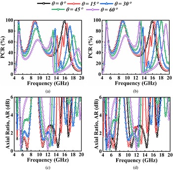
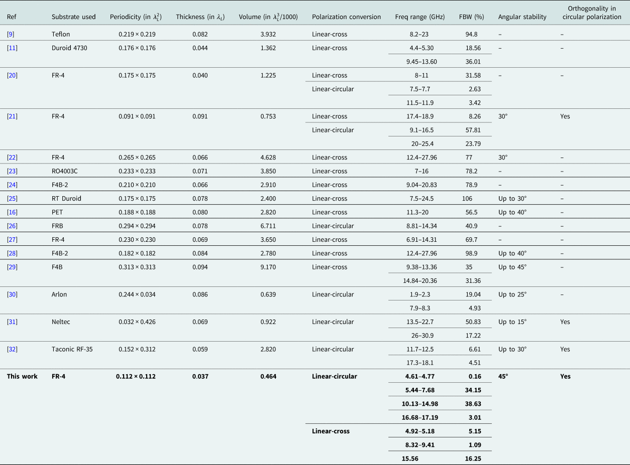
For the oblique TE incidence, the transmitting and receiving antennas were moved away from the normal of the designed metasurface. The incident angle is varied from 0° to 60° in steps of 15°, and the reflectance measurement was done for both co-and cross-pol components. Both the antennas were rotated by 90° for the TM case. The measured PCR and AR (dB) for TE and TM incidences are depicted in Fig. 11. The proposed polarizer's performance is compared to Table 2's other recently reported state-of-the-art designs. The authors strongly believe that this design has the potential which can be suitable for real-time applications due to its compact size and multi-conversion performance with circular rotation switching in consecutive bands.
Measured PCR for the (a) TE, (b) TM, and AR (dB) for the (c) TE and (d) TM modes for different elevation angles (θ).

Performance comparison of the proposed design with other recently reported state-of-the-art polarizers

*λL is the free-space wavelength corresponding to the band's lowest frequency.
Conclusion
The novel figure-of-eight squared loop linked with arrow type FSS-based multiband linear-cross and linear-circular reflective type polarizer is proposed in this article. The prototype is fabricated, and a good understanding is observed with the simulated results. Surface plasmonic resonances are the reason behind these conversions. The design novelties lie in its size, multiband conversion (linear-cross and linear-circular) with switching circular rotations sense in the consecutive band, and considerable stable performance for oblique incidence, making this polarizer a better candidate for real-time needs.
Acknowledgements
This work is supported by Science and Engineering Research Board (SERB), Govt of India under project no: ECR/2018/002258.
 Mohammad Abdul Shukoor (Graduate Student Member, IEEE) received the bachelor's degree (B.Tech.) in Electronics and Communication Engineering Department from RVR & JC College of Engineering, Guntur, India, in 2013, the master's degree (M.Tech.) in radar and microwave engineering from Andhra University, Visakhapatnam, India, in 2016. He is working toward a Ph.D. with the Department of Electrical Engineering, Indian Institute of Technology Palakkad, Palakkad, India. His current research interests include metamaterial-based absorbers, FSS, and polarization converters. He has published more than 20 research articles and filed four Indian patents. Abdul Shukoor was the recipient of the Best Paper Awards in IEEE Conferences like International IoT, Electronics and Mechatronics Conference, Vancouver, BC, Canada, in 2020, and WAMS 2022.
 Sukomal Dey (Senior Member, IEEE) received the B.Tech. degree in electronics and communication engineering from the West Bengal University of Technology, Kolkata, India, in 2006, the M.Tech. degree in mechatronics engineering from the Indian Institute of Engineering Science and Technology, Shibpur, India, in 2008, and the Ph.D. degree from the Centre for Applied Research in Electronics, Indian Institute of Technology Delhi, New Delhi, India, in July 2015. From August 2015 to July 2016, he was a Project Scientist with Industrial Research and Development Centre, IIT Delhi, and also worked on a collaborative research project supported by Synergy Microwave Corp., Paterson, NJ, USA. From August 2016 to June 2018, he was with Radio Frequency Microsystem Lab, National Tsing Hua University, Taiwan, as a Post doctorate Research Fellow. Since June 2018, he has been an Assistant Professor with the Department of Electrical Engineering, Indian Institute of Technology Palakkad, Palakkad, India. For his M.Tech. dissertation (one year), he was with Central Electronics Engineering Research Institute, Pilani, India, in 2009. He has authored or co-authored more than 100 research papers, two state-of-the art books, two book chapters, and filed 15 patents. His research interests include electromagnetic metamaterial structures, frequency-selective surfaces, microwave imaging, and microwave-integrated circuits, including antennas and RFMEMS. Dr. Dey was the recipient of the Postgraduate Student Award from the Institute of Smart Structure and System, Bangalore, India, in 2012, Best Industry Relevant Ph.D. Thesis Award from the Foundation for Innovation in Technology Transfer, IIT Delhi, in 2016, Postdoctoral Fellow Scholarships from the Ministry of Science and Technology, Taiwan, in 2016 and 2017, respectively, Early Career Research Award from the Science and Engineering Research Board (SERB), Government of India, in 2019, Smt. Ranjana Pal Memorial Award (2021) from the Institution of Electronics and Communication Engineers, and several best paper awards from national and international IEEE conferences with his students. He is the potential reviewers of many prestigious IEEE journals, such as IEEE Transactions on Electromagnetic Compatibility, IEEE Transactions on Antenna and Propagations, IEEE Transactions on Microwave Theory and Techniques, and IEEE/ASME Journal of Microelectromechanical System. He has been inducted in the technical program committee 4 and 6 of the IEEE MTT Society.