I. INTRODUCTION
NiAl–Cr(Mo) eutectic alloy exhibits a promising room temperature and elevated temperature properties Reference Johnson, Chen, Oliver, Noebe and Whittenberger1 and possesses some advantages, such as a high melting point, good thermal conductivity, and excellent oxidation resistance. Reference Noebe, Bowman and Nathal2 However, compared to Ni-based superalloy, NiAl–Cr(Mo) eutectic alloy is not satisfied for the application of aeroengine blade due to the lower elevated temperature strength. It was reported that the refractory Cr(Mo) phase can effectively improve the room temperature brittleness and elevated temperature strength of NiAl through the common bridging mechanism of Cr(Mo) phase, Reference Johnson, Chen, Oliver, Noebe and Whittenberger1,Reference Yu, Bei, Chen, George and An3–Reference Misra, Gibala and Noebe5 and the volume fraction of Cr(Mo) phase in NiAl–32Cr–6Mo hypereutectic alloy is higher than that of NiAl–Cr(Mo) eutectic alloy. Reference Shang, Shen, Wang, Du, Xiong and Fu6 Therefore, we take NiAl–32Cr–6Mo hypereutectic alloy as a matrix alloy in this paper. Guo and Cui et al. Reference Guo, Cui, Chen, Li and Ye7–Reference Cui, Guo, Qi and Ye9 reported that the addition of Hf element (0.5 at.%) enhances the elevated temperature strength of NiAl–Cr(Mo) eutectic alloy, but causes the room temperature brittleness due to the existence of Heusler phase at NiAl/Cr(Mo) interface. Thus, we attempt to reduce the additive content of Hf to maintain a good combination property in this paper. Furthermore, the rare earth element Dy may improve the property of the alloy by the microstructural refinement and interface purification (enhancing interface strength). Reference Sheng, Wang, Хi, Zheng and Ye10–Reference Wang, Shen, Shang and Fu14
In addition, the well-aligned lamellar structure can be obtained for NiAl–Cr(Mo) eutectic system alloy by directional solidification technique. Johnson et al. Reference Johnson, Chen, Oliver, Noebe and Whittenberger1 have reported that high temperature gradient enhances the orderliness of the lamellar structure further. Here, we introduce two directional solidification methods which are liquid metal cooling (LMC) technique and zone melted liquid metal cooling (ZMLMC) technique. In the LMC technique, the sample is wholly melted in a crucible. However, in the ZMLMC technique, the sample is locally melted in the crucible. What's more, higher temperature gradient can be achieved in the ZMLMC technique. Generally, higher temperature gradient may result in the formation of a better-aligned structure, Reference Hunt and Jackson15 thus may obtain a better mechanical property. However, for NiAl–32Cr–6Mo hypereutectic alloy, the LMC technique and ZMLMC technique are rarely investigated simultaneously. Therefore, the paper investigates the microstructure, room temperature compressive property, and elevated temperature tensile property of (Hf,Dy)-doped NiAl–32Cr–6Mo hypereutectic alloy by the directional solidification technique (LMC and ZMLMC).
II. EXPERIMENTAL DETAILS
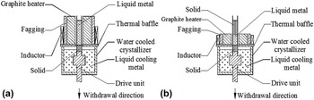
The master alloy of Ni–30.95Al–32Cr–6Mo–0.05Hf (at.%)–0.1Dy (wt%) alloy [NiAl–Cr(Mo)–(Hf,Dy) for short] was prepared by vacuum induction melting. The Ф9 mm rods were cut from the ingots by wire electrodischarge machining (EDM) and placed in the high purity alumina crucible with 9.1 mm inner diameter for directional solidification in Bridgeman apparatus with induction heating (Baoji, China). Figure 1 shows the schematic diagrams of LMC and ZMLMC directional solidifications. The LMC and ZMLMC techniques are controlled by different induction heating coils. The melt temperature was 1660 ± 10 °C, and the temperature gradients at the solid–liquid interface in the LMC and ZMLMC directional solidification were about 200 K/cm and 600 K/cm, respectively. The temperature in the specimen was measured with 0.5 mm diameter insulated W–Re thermocouples inserted into the dual-hole alumina fixed within the sample. Two W–Re thermocouples were connected to the measurement unit which consists of data-logger and computer. The temperature gradient (G = ΔT/ΔX) in the liquid phase was determined by the values of ΔT and ΔX. The specimen was pulled down at the withdrawal rates of 10, 30, 60, and 120 μm/s in the LMC directional solidification. The pulling length of the directionally solidified specimen is 60 mm. For the ZMLMC directional solidification, we take 30 μm/s for example, since a better mechanical property can be obtained at a moderate withdrawal rate. Reference Raj, Locci, Salem and Pawlik16
Schematic diagrams of (a) LMC and (b) ZMLMC directional solidifications.

The directionally solidified specimens were cut along the longitudinal and transverse directions, and the location of cross-section was 5 mm below the solid–liquid interface. The sections were mechanically polished and then etched with a solution of 80% HCl + 20% HNO3 by volume. The microstructures were observed by scanning electron microscopy (SEM). The composition of the constituent phase was identified by energy dispersive spectroscopy (EDS).
The compression specimens with the size of 4 × 4 × 6 mm3 were cut from directional solidified ingots by EDM, and all major surfaces were ground with 2000-grit SiC abrasive prior to compression test. The compression tests were conducted in an Instron 3382 universal test machine (Norwood, Massachusetts) at a strain rate of 2 × 10⁻³ s−1, and the compression axis is parallel to the growth direction. Tensile specimens having a gauge section of 3 × 3 × 17 mm3 were cut from the directional solidification (DS) alloy along the growth direction by EDM, and all the surfaces of specimens were ground with 2000-grit SiC abrasive. Tensile tests were performed at 1253 K and a strain rate of 1 × 10⁻⁴ s−1 on an ultratemperature tensile testing machine. In this work, three specimens were tested and the average value was adopted for each specimen condition.
III. RESULTS AND DISCUSSION
A. Microstructure
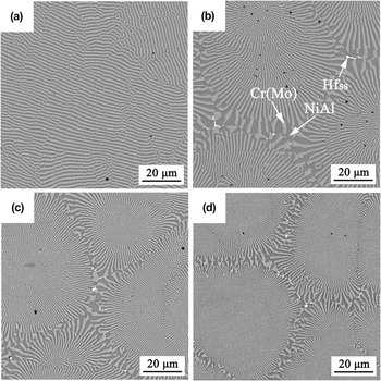
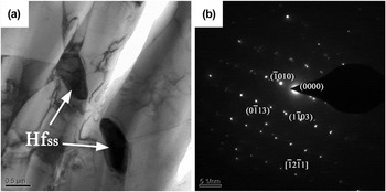
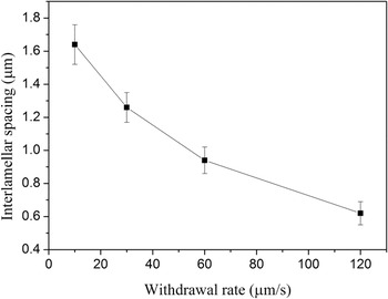
The SEM micrographs of transverse microstructures of LMC alloy are shown in Fig. 2. The planar eutectic lamellar structure is observed at 10 μm/s, and consists of black NiAl (Ni: 47.8 at.%, Al: 47.6 at.%, Cr: 4.6 at.%) and gray white Cr(Mo) (Cr: 74.6 at.%, Mo: 10.2 at.%, Ni: 6.1 at.%, Al: 9.1 at.%), as displayed in Fig. 2(a). When the withdrawal rate exceeds 10 μm/s, the microstructure consists of eutectic cells in different sizes. The eutectic cell consists of alternating NiAl and Cr(Mo) lamellae with a radial emanating pattern from the cell interior outward to the cell boundary, and the lamellae at the cell periphery are thicker than those at the cell center, as displayed in Figs. 2(b)–2(d). Besides NiAl and Cr(Mo) phases, the white phase is observed in the cell boundary and identified as Hf solid solution (Hfss) by SEM-EDS (Hf: 83.5 at.%, Ni: 9.6 at.%, Cr: 6.9 at.%). The content of Hf in Hfss phase is close to pure Hf, and a small content of Ni and Cr dissolved in the Hfss phase. It is deduced that the structure of Hfss phase is the same with that of pure Hf (hexagonal close-packed structure). Meanwhile, the TEM image of Hfss phase is observed, and the selected area diffraction pattern of Hfss phase is obtained, as shown in Fig. 3. The result shows that Hfss phase has a close-packed hexagonal structure with c/a = 1.917. The result is also similar to previous investigations in which Hf solid solution (Hfss) is usually observed when the additional content of Hf is no more than 0.2 at.%. Reference Cui, Guo, Qi and Ye9,Reference Wang, Shen, Shang, Zhang, Chen and Fu13,Reference Wang and Shen17–Reference Liang, Guo, Xie, Sheng, Zhou and Hu19 Moreover, with increasing the withdrawal rate, the area of cell boundary increases gradually along with more homogeneous distribution of the Hfss phase. Furthermore, the average interlamellar spacing (measured in the eutectic cell interior) decreases gradually with increasing the withdrawal rate, as shown in Fig. 4.
Transverse microstructure of NiAl–Cr(Mo)–(Hf,Dy) hypereutectic alloy obtained by LMC technique at (a) 10, (b) 30, (c) 60, (d) 120 μm/s.

(a) TEM image of Hfss phase and (b) selected area diffraction pattern of Hfss phase.

Average interlamellar spacing of LMC alloy at different withdrawal rates.

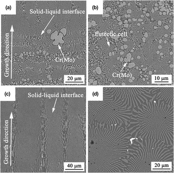
Beside the LMC solidified structure, we also simply introduce the ZMLMC solidified structure. According to previous investigation, Reference Raj, Locci, Salem and Pawlik16 a better mechanical property can be obtained at a moderate withdrawal rate which is slightly higher than the planar → cellular transitional rate. Thus, for simplification, we take 30 μm/s for example in the ZMLMC directional solidification. Longitudinal and transverse microstructures of ZMLMC alloy are observed, as shown in Figs. 5(a) and 5(b), respectively. The result shows that the Cr(Mo) primary phase appears in the ZMLMC alloy and grows preferentially at the solid–liquid interface front. And, the lamellar structure is disordered and not parallel to the growth direction. It can also be seen from Fig. 5(a) that the solid–liquid interface morphology is difficultly identified as planar, cellular, or dendritic due to the disordered structure. For comparison, the corresponding microstructures of LMC alloy are given in Figs. 5(c) and 5(d). The result indicates that the microstructure of ZMLMC alloy is completely different from that of LMC alloy. In the LMC alloy, the lamellar structure is well-aligned and parallel to the growth direction, and the microstructure consists of the fully eutectic structures. And, the solid–liquid interface morphology is easily identified as cellular. The different microstructures may result in the difference of mechanical properties.
Microstructures of the ZMLMC alloy [(a) solid–liquid interface and (b) transverse microstructure] and the LMC alloy [(c) solid–liquid interface and (d) transverse microstructure] at 30 μm/s.

Generally, the well-aligned lamellar structure is obtained at a higher temperature gradient Reference Johnson, Chen, Oliver, Noebe and Whittenberger1 where the growth of the primary phase is suppressed. Reference Hunt and Jackson15 It is interesting that the fully and well-aligned lamellar structure is obtained in the LMC directional solidification with a relatively low temperature gradient, but the disordered lamellar structure and the Cr(Mo) primary phase are observed in the ZMLMC directional solidification with a high temperature gradient. For the LMC and ZMLMC directional solidifications, besides the difference of temperature gradient, the major difference of two solidification ways is the length of melting zone (see Fig. 1). That is, the whole specimen is melted in the LMC technique. However, the local zone of specimen is melted in the ZMLMC technique, and the specimen is melted step by step at a fixed molten rate (30 μm/s).
In the LMC directional solidification, the length of melting zone is larger, and the more amount of heavy element (like Mo) may sink to the bottom from the top of the melt. Therefore, the composition of the bottom of the melt is largely deviated from the eutectic composition, thus the Cr(Mo) primary phase appears in the bottom of specimen, as reported in Ref. Reference Wang, Shen, Shang, Zhang, Chen and Fu13. As the solidification proceeds, the composition of the melt may become the eutectic composition (C E) along the liquidus, and the fully eutectic structure is obtained, as shown in Figs. 5(c) and 5(d). However, in the ZMLMC directional solidification, the sample is locally melted, and the unmelted sample is melted step by step at the molten rate of 30 μm/s. Due to the step-by-step melting, the liquid composition of melting zone is always close to the initial composition. Therefore, the liquid composition maintains always in the hypereutectic composition, thus resulting in the appearance of the Cr(Mo) primary phase, as shown in Figs. 5(a) and 5(b). In addition, recent investigation Reference Shang, Shen, Wang, Du, Xiong and Fu6 reported that the microstructures have no significant difference at 6 μm/s for LMC and ZMLMC techniques, and the fully eutectic structure (planar eutectic) is obtained. This indicates that the fully eutectic structure can be gained at a low withdrawal rate, but cannot be acquired at a high withdrawal rate by ZMLMC technique. This may be attributed to the different undercooling degrees at different withdrawal rates. That is, from the metal–metal coupled growth zone, Reference Stefanescu20 the melt undercools into the planar eutectic zone when the withdrawal rate is lower, and undercools into the eutectic + primary dendrite zone when the withdrawal rate is higher. Furthermore, previous investigation reported that the composition of last zone of specimen decreased for the hypereutectic alloy (k > 1, k is solute equilibrium partition coefficient) by ZMLMC technique. Reference Hu, Cai and Rong21 Here, the pulling length is 60 mm in the present ZMLMC experiment. Therefore, we predict that the microstructure may become fully eutectic structure when the pulling length is long enough. In a word, for the present alloy, the LMC technique will be more appropriate, since a high withdrawal rate is suited to the industrial application.
B. Room temperature compressive property
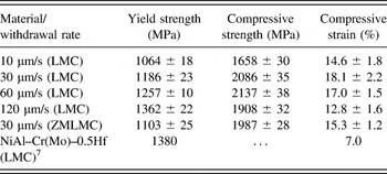
Room temperature compressive properties of LMC alloys at different withdrawal rates are given in Table I. The result shows that the yield strength of LMC alloy increases gradually with increasing the withdrawal rate. The decrease of interlamellar spacing should be responsible for the increase of yield strength, since the interface of the two-phase lamellar structure hinders the motion of dislocation. Moreover, the more homogeneous distribution of Hfss phase at the higher withdrawal rate enhances the yield strength by precipitation strengthening. The highest yield strength of LMC alloy reaches 1362 ± 22 MPa which is close to or slightly lower than that of traditionally high-strength NiAl–Cr(Mo)–0.5Hf eutectic alloy [LMC, 1380 MPa (Ref. Reference Guo, Cui, Chen, Li and Ye7)]. For NiAl–Cr(Mo) hypereutectic alloy, the volume fraction of the Cr(Mo) lamellar phase increases, Reference Shang, Shen, Wang, Du, Xiong and Fu6 which results in the enhancement of yield strength. However, the strengthening effect of 0.05 at.% Hf in the present LMC alloy is much lower than that of 0.5 at.% Hf, since Hf is a typical strengthening element. Therefore, the yield strength of LMC alloy is slightly lower than that of traditionally high-strength NiAl–Cr(Mo)–0.5Hf eutectic alloy (LMC). The compressive strength and strain is relatively higher at a moderate withdrawal rate, but decreases at the higher withdrawal rate (120 μm/s). The higher withdrawal rate (120 μm/s) results in the refinement of eutectic cells, and thus leads to the increase of the area of the intercellular region, as shown in Fig. 2. Generally, the intercellular region is weak, thus facilitating the propagation of crack. Reference Raj, Locci, Salem and Pawlik16,Reference Wang and Shen18 Accordingly, the compressive strength decreases at the higher withdrawal rate (120 μm/s). For comparison, the compressive property of ZMLMC alloy at 30 μm/s is also provided. The result indicates that the compressive/yield strength of ZMLMC alloy is lower than that of LMC alloy. The low compressive property of ZMLMC alloy should be attributed to the existence of the Cr(Mo) primary phase and disordered lamellar structure.
Room temperature compressive properties of LMC and ZMLMC alloys at 2 × 10⁻³ s−1.

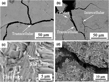
To understand the fracture behavior, the crack propagations in the end surfaces (transverse) of LMC and ZMLMC compressive specimens are observed. It can be seen from Fig. 6(a) that the transcellular fracture frequently occurs in the LMC compressive specimen. However, in the ZMLMC compressive specimen, the intercellular and transcellular fractures are simultaneously observed, and the crack propagation also occurs in the Cr(Mo) primary phase, as shown in Fig. 6(b). Generally, compared to the intercellular fracture, the transcellular fracture can provide more resistances to crack propagation. Therefore, compared to the ZMLMC alloy, the LMC alloy possesses a higher strength. Meanwhile, we also observe the fracture surfaces of LMC and ZMLMC compressive specimens. The typical fracture surface morphology exhibits the cleavage of NiAl and the shear rib of Cr(Mo), as displayed in Fig. 6(c). The shear rib of Cr(Mo) lamella provides more resistances to crack propagation because of its higher strength. However, in the ZMLMC compressive specimen, the fracture morphology is disordered and chaos, which is consistent with the disordered microstructure, and the shear rib of Cr(Mo) lamella is not almost observed, as shown in Fig. 6(d). Therefore, the observations of crack propagation and fracture surface roughly indicate that the LMC alloy has a higher strength in comparison to the ZMLMC alloy.
Crack propagations and fracture surfaces of compressive specimens [(a and c) LMC and (b and d) ZMLMC].

C. Elevated temperature tensile property
The final aim of the investigation about NiAl–Cr(Mo) eutectic alloy is that the alloy can be applied at a high temperature environment. Thus, the elevated temperature tensile experiments of LMC and ZMLMC alloys are performed, and the data are given in Table II. For comparison, the elevated temperature properties of similar compositional alloys are also provided in Table II. The result shows that the elevated temperature strength of LMC alloy is obviously higher than that of ZMLMC alloy, and it is also higher than that of NiAl–Cr(Mo)–0.5Hf (LMC). Reference Guo, Cui, Chen, Li and Ye7 Generally, the elevated temperature strength increases gradually with the increase of strain rate. Thus, it is reasonably deduced that the elevated temperature strength of present alloy (LMC) is higher than that of NiAl–Cr(Mo)–(Hf,Ho) alloys (LMC). Reference Liang, Guo, Xie, Sheng, Zhou and Hu19 In a word, the present alloy obtained by the LMC technique possesses higher elevated temperature strength.
Elevated temperature tensile properties of LMC and ZMLMC alloys at 30 μm/s.

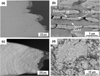
To better understand the fracture behavior of tensile specimen, the side surface near the fracture surface is observed. Figure 7(a) shows the side surface morphology of LMC specimen, and no significant plastic deformation (only 3.3 ± 0.5% in Table II) is observed. From the highly magnified image, the NiAl phase is relatively intact, and the breaking occurs in the Cr(Mo) phase, as displayed in Fig. 7(b). Because the strength of the NiAl phase is lower than that of the Cr(Mo) phase, the NiAl phase has a better ductility in comparison to the Cr(Mo) phase. Thus, the breaking of the Cr(Mo) phase provides more resistances to crack propagation by the bridging mechanism. Moreover, due to the differences of strength and ductility of NiAl and Cr(Mo) phases, the discordance of deformation leads to the occurrence of interface debonding, as shown in Fig. 7(b). The interface debonding also provides some resistances to crack propagation, thus obtaining a higher strength. Figure 7(c) shows the side surface morphology of ZMLMC specimen, and the result shows that an obvious plastic deformation occurs during the fracture process. Unlike the LMC alloy, the magnified image of the ZMLMC specimen indicates that the microstructure has a significant deformation, and the original microstructure [disordered structure and Cr(Mo) primary phase] has not been completely observed, as shown in Fig. 7(d). This also indicates that the thermal endurance of the microstructure of ZMLMC alloy is worse than that of LMC alloy in the present experiment. Therefore, the observation of side surface also demonstrates that the strength of LMC alloy is more than that of ZMLMC alloy in the present investigation.
Side surfaces near fracture surfaces of (a and b) LMC and (c and d) ZMLMC alloys.

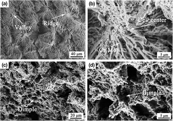
Meanwhile, the corresponding fracture surfaces are also observed to clarify the fracture behavior. The fracture surface of LMC alloy is tortuous and consists of the intracellular ridges and valleys, as illustrated in Fig. 8(a), thus providing some resistances to crack propagation. It can also be seen from Fig. 8(b) that the eutectic cell center is more tortuous and may supply more resistances to crack propagation, and the shear rib of Cr(Mo) lamellae also hinders the crack propagation. In the ZMLMC alloy, many dimples are observed, as displayed in Figs. 8(c) and 8(d). This indicates that the ZMLMC alloy possesses a better ductility. That is, the observation of fracture surface demonstrates that the LMC alloy may possess a high strength and the ZMLMC alloy has a better ductility.
Fracture surfaces of (a and b) LMC and (c and d) ZMLMC alloys.

D. Strengthening mechanism
In the present investigation, the compressive yield strength of LMC alloy increases gradually with increasing the withdrawal rate due to the refinement of lamellar structure. And, the combination property of LMC alloy is better than that of ZMLMC alloy. This is attributed to the existence of well-aligned lamellar structure in the LMC alloy. In addition, compared to the traditionally high-strength NiAl–Cr(Mo)–0.5Hf eutectic alloy (LMC), NiAl–Cr(Mo)–(Hf,Dy) hypereutectic alloy obtained by the LMC technique possesses a better combination property. Chen et al. Reference Chen, Johnson, Noebe and Oliver4 and Misra et al. Reference Misra, Gibala and Noebe5 thought that refractory Cr(Mo) phase can increase the combination property through the significant bridging mechanism. Lately, recent investigation reported that the volume fraction of Cr(Mo) phase in NiAl–32Cr–6Mo hypereutectic alloy is higher than that of NiAl–Cr(Mo) eutectic alloy. Reference Shang, Shen, Wang, Du, Xiong and Fu6 Therefore, NiAl–Cr(Mo)–(Hf,Dy) hypereutectic alloy possesses the higher room temperature compressive/yield strength and elevated temperature strength. In addition, the nanosize precipitates are commonly observed in the NiAl or Cr(Mo) phase. Reference Guo, Cui, Chen, Li and Ye7,Reference Cui, Guo, Qi and Ye8,Reference Wang, Shen, Shang and Fu14,Reference Wang and Shen17,Reference Wang and Shen18 Generally, the existence of nanosize precipitates can also improve the strength by precipitation strengthening. Furthermore, the addition of rare earth element Dy reduces the segregation of impurities O, S, and C in the interface, and thus enhances the cohesive strength of phase/cell interface. Thus, the addition of rare earth element Dy also improves the property of the alloy by strengthening the interface.
IV. CONCLUSION
In this paper, we investigated the microstructure, room temperature compressive property, and elevated temperature tensile property of directionally solidified NiAl–Cr(Mo)–(Hf,Dy) hypereutectic alloy obtained by the LMC and ZMLMC technique. The obtained results are summarized as follows:
-
(1) The well-aligned and fully eutectic lamellar structure is obtained by the LMC technique. However, the disordered eutectic lamellar structure and Cr(Mo) primary phase are gained by the ZMLMC technique.
-
(2) The interlamellar spacing decreases gradually with increasing the withdrawal rates in the LMC alloy, thus improving the compressive yield strength.
-
(3) Compared to the ZMLMC technique, the LMC technique improves a higher combination property of NiAl–Cr(Mo)–(Hf,Dy) hypereutectic alloy due to the well-aligned lamellar structure.
ACKNOWLEDGMENTS
The work is supported by the National Natural Science Foundation of China (No. 51501147), the doctoral starting fund of Xi'an University of Technology (101-451115004), the fund of the State Key Laboratory of Solidification Processing in NWPU (SKLSP201509) and National Natural Science Foundation of China (No. 51074128).