1. Introduction
Laminar pipe flow of a Newtonian fluid is well known to be linearly stable at all Reynolds numbers (Drazin & Reid Reference Drazin and Reid1981; Schmid & Henningson Reference Schmid and Henningson2001; Meseguer & Trefethen Reference Meseguer and Trefethen2003), and a rigorous theoretical description of the onset of turbulence in this flow has therefore remained an outstanding challenge in fluid dynamics research for more than a century (Eckhardt et al. Reference Eckhardt, Schneider, Hof and Westerweel2007). Experiments since the classic work of Reynolds (Reference Reynolds1883) have shown that the transition to turbulence occurs at a Reynolds number  $Re \approx 2000$ (Avila et al. Reference Avila, Moxey, De Lozar, Barkley and Hof2011; Mullin Reference Mullin2011), in stark contrast to the aforementioned prediction of linear stability theory. As shown originally by Reynolds himself, the transition can be delayed considerably, even up to
 $Re \sim 10^5$ (Pfenniger Reference Pfenniger1961), by carefully minimizing external perturbations, thus pointing to the importance of nonlinear effects. The relatively recent discovery of nonlinear three-dimensional solutions (termed ‘exact coherent states’, ECSs) of the Navier–Stokes equations for pipe flow has considerably advanced our understanding in this regard by providing the framework for a nonlinear, subcritical route to transition. Such solutions are disconnected from the laminar state, appearing via saddle-node bifurcations with increasing
 $Re$ and closely resembling coherent structures in the turbulent buffer layer (Waleffe Reference Waleffe1998; Kerswell Reference Kerswell2005; Eckhardt et al. Reference Eckhardt, Schneider, Hof and Westerweel2007). Further, spatially localized ECSs (calculated in a symmetry-reduced subspace; see Avila et al. Reference Avila, Mellibovsky, Roland and Hof2013) have been shown to bear both structural and dynamical resemblance to turbulent puffs observed in pipe flow experiments (Wygnanski & Champagne Reference Wygnanski and Champagne1973; Wygnanski, Sokolov & Friedman Reference Wygnanski, Sokolov and Friedman1975). The existence of such solutions has led to a new dynamical systems perspective, wherein transitional turbulence in a pipe is interpreted as a wandering trajectory in an appropriate phase space which visits the neighbourhood of multiple invariant sets (including the aforementioned solutions) in a seemingly unpredictable manner (Budanur et al. Reference Budanur, Short, Farazmand, Willis and Cvitanović2017).
The onset of turbulence in pipe (and channel) flow of viscoelastic polymer solutions, however, remains largely unexplored (Larson Reference Larson1992). Flows of dilute polymer solutions, where shear thinning effects are insignificant, are known to be susceptible to purely elastic linear instabilities even in the absence of inertia (Shaqfeh Reference Shaqfeh1996), but only in flows with curved streamlines as in the Taylor–Couette or Dean geometries (note that linear instabilities have been reported even in rectilinear shear flows when fluid inertia is insignificant, but only for concentrated polymer solutions, where effects of both elasticity and shear thinning become important; see Wilson & Rallison Reference Wilson and Rallison1997; Bodiguel et al. Reference Bodiguel, Beaumont, Machado, Martinie, Kellay and Colin2015; Wilson & Loridan Reference Wilson and Loridan2015). The instability in flows with curved streamlines eventually leads to a disorderly flow state (termed ‘elastic turbulence’; Groisman & Steinberg Reference Groisman and Steinberg2000), and the transition manifests as an enhanced drag above a threshold Weissenberg number,  $W$, defined as the product of the shear rate and the longest polymer relaxation time. In contrast, the addition of small amounts of polymers to turbulent pipe flow leads to a drastic reduction in the frictional drag (Virk Reference Virk1975b), a phenomenon called turbulent drag reduction that has been investigated extensively (White & Mungal Reference White and Mungal2008; Graham Reference Graham2014; Xi Reference Xi2019). There is relatively little discussion in the drag reduction literature, however, of the role of the added polymers on turbulence onset. Nevertheless, there have been some reports of ‘early turbulence’ in pipe flow of polymer solutions, beginning in the 1960s (Ram & Tamir Reference Ram and Tamir1964; Goldstein, Adrian & Kreid Reference Goldstein, Adrian and Kreid1969; Forame, Hansen & Little Reference Forame, Hansen and Little1972; Hansen, Little & Forame Reference Hansen, Little and Forame1973; Hansen & Little Reference Hansen and Little1974; Jones, Marshall & Walker Reference Jones, Marshall and Walker1976; Hoyt Reference Hoyt1977; Zakin et al. Reference Zakin, Ni, Hansen and Reischman1977), wherein transition was observed to occur at
 $Re$ much lower than 2000. Recent experiments (Samanta et al. Reference Samanta, Dubief, Holzner, Schäfer, Morozov, Wagner and Hof2013; Srinivas & Kumaran Reference Srinivas and Kumaran2017; Chandra, Shankar & Das Reference Chandra, Shankar and Das2018, Reference Chandra, Shankar and Das2020; Choueiri, Lopez & Hof Reference Choueiri, Lopez and Hof2018) have demonstrated convincingly that at sufficiently high polymer concentrations (
 $>$300 ppm for pipes and
 $>$80 ppm for channels), flow of polymer solutions in pipes and channels does indeed become unstable at Reynolds numbers much lower (
 ${\sim }800$ for pipes and
 ${\sim }200$ for micro-channels) than those corresponding to the Newtonian transition. To differentiate it from conventional Newtonian turbulence, the ensuing flow state has been referred to as ‘elasto-inertial turbulence’ (EIT; see Samanta et al. Reference Samanta, Dubief, Holzner, Schäfer, Morozov, Wagner and Hof2013) pointing to the importance of both elastic and inertial forces in the underlying dynamics.
Although the possibility of a linear instability in viscoelastic plane shear flows has occasionally been speculated upon (Graham Reference Graham2014), most of the literature has extrapolated the Newtonian scenario to the viscoelastic case, assuming viscoelastic pipe flows to also be linearly stable. This viewpoint has been stated explicitly in several earlier studies (see, for example, Bertola et al. (Reference Bertola, Meulenbroek, Wagner, Storm, Morozov, van Saarloos and Bonn2003), Morozov & van Saarloos (Reference Morozov and van Saarloos2005), Pan et al. (Reference Pan, Morozov, Wagner and Arratia2013) and Sid, Terrapon & Dubief (Reference Sid, Terrapon and Dubief2018), in particular) despite the absence of a systematic exploration of the larger parameter space in the viscoelastic case where, in addition to the Reynolds number  $Re$, the elasticity number
 $E$ (which is a ratio of the polymer relaxation to the momentum diffusion timescales;
 $E = W/Re$) and the ratio of solvent to total solution viscosity
 $\beta$ are also expected to influence stability. Indeed, the presumed stability of viscoelastic pipe flow to infinitesimal disturbances is so ingrained in the field that, prior to the present effort, there has not been a linear stability analysis using a realistic constitutive model for viscoelastic pipe flow. The only reported stability analysis for the pipe geometry (Hansen Reference Hansen1973; Hansen et al. Reference Hansen, Little and Forame1973) neglects the crucial convected nonlinearities in the Oldroyd-B constitutive relation, and hence does not account for an essential feature of polymer rheology. The lack of emphasis on a viscoelastic transition triggered by a linear instability is particularly perplexing in light of the unambiguous experimental evidence of the critical Reynolds numbers being same for the unperturbed and externally perturbed transition scenarios for sufficiently concentrated (
 ${\sim}300$ ppm onwards) polymer solutions (see figure 3a of Samanta et al. Reference Samanta, Dubief, Holzner, Schäfer, Morozov, Wagner and Hof2013).
In a recent letter (Garg et al. Reference Garg, Chaudhary, Khalid, Shankar and Subramanian2018), we demonstrated, for the first time, that elastic, viscous and inertial effects in polymer solutions (modelled as Oldroyd-B fluids) can combine to render viscoelastic pipe flow linearly unstable at Reynolds numbers much lower than 2000. In this paper, we build on this discovery by (i) providing a detailed picture on the origin of the instability, (ii) augmenting the original results by exploring a larger parameter space and (iii) comparing our theoretical predictions with existing experimental observations and direct numerical simulations (DNS). We also provide a perspective on how the presence of a linear instability in viscoelastic pipe flow can potentially alter the prevailing paradigm for laminar–turbulent transition and turbulent drag reduction in polymer solutions. In the remainder of this introduction, we review relevant earlier work on this subject under the following headings: (i) Newtonian transition, (ii) turbulent drag reduction, (iii) experimental studies on the onset of turbulence in viscoelastic flows, (iv) computational bifurcation studies and DNS and (v) stability analyses of viscoelastic shearing flows. Finally, the specific objectives for the present work are laid out in the context of the existing paradigm with regards to the viscoelastic transition.
1.1. Newtonian pipe-flow transition
Classical modal stability analyses (Corcos & Sellars Reference Corcos and Sellars1959; Gill Reference Gill1965a,Reference Gillb; Garg & Rouleau Reference Garg and Rouleau1972; Salwen & Grosch Reference Salwen and Grosch1972) have found fully developed pipe flow to be linearly stable even up to  $Re \sim 10^7$ (Meseguer & Trefethen Reference Meseguer and Trefethen2003). The Newtonian eigenspectrum for pipe flow, for sufficiently high
 $Re$, conforms to the characteristic ‘Y-shaped’ locus known for canonical shearing flows (plane Couette and Poiseuille flows; see Schmid & Henningson Reference Schmid and Henningson2001), with three distinct branches: the ‘A branch’ corresponding to ‘wall modes’ with phase speeds approaching zero, the ‘P branch’ corresponding to ‘centre modes’ with phase speeds tending to the maximum base flow velocity and the ‘S branch’ with modes having a phase speed intermediate between those for wall and centre modes. Although a wall mode belonging to the A branch becomes unstable in plane channel flow of a Newtonian fluid at
 $Re > 5772$ (the Tollmien–Schlichting (TS) instability, see Drazin & Reid Reference Drazin and Reid1981), all three branches remain stable for Newtonian pipe flow regardless of
 $Re$, with the phase speed of the modes belonging to the S branch equalling two-thirds of the base-state maximum. The prediction of stability to infinitesimal disturbances at any Reynolds number is broadly consistent with experiments, wherein, as stated previously, the transition can be delayed up to
 $Re \sim 10^5$ (Pfenniger Reference Pfenniger1961), by carefully controlling the inlet conditions. Henceforth, we refer to this transition scenario, which is highly sensitive to inlet conditions, as a ‘natural’ transition, whereas the transition that occurs at the oft-quoted Reynolds number of around 2000 will be referred to as a ‘forced’ transition. Although the natural transition for the Newtonian case is a sensitive function of experimental conditions, the forced transition is quite robust (in fact, an exact critical point exists, as first demonstrated by Avila et al. (Reference Avila, Moxey, De Lozar, Barkley and Hof2011); we return to this point, briefly, in the conclusions section). The difference between the associated threshold
 $Re$ arises, of course, owing to the subcritical nature of the Newtonian transition.
The predictions from a modal analysis are only concerned with asymptotic behaviour at long times. More than a century after Reynolds’ experiments, a series of studies in the early 1990s (Butler & Farrell Reference Butler and Farrell1992; Reddy & Henningson Reference Reddy and Henningson1993; Trefethen et al. Reference Trefethen, Trefethen, Reddy and Driscoll1993) demonstrated the possibility of short-time growth of the disturbances, even when all eigenmodes are stable. This early time growth was attributed to the non-normal nature of the linearized operator underlying Newtonian stability, leading to the eigenfunctions corresponding to different eigenvalues not being orthogonal (Grossmann Reference Grossmann2000; Schmid Reference Schmid2007). The (non-exponential) growth, variously referred to as non-modal, transient or algebraic growth, was regarded as the reason for the amplification of initial disturbances to a sufficiently large magnitude such that nonlinearities can become important, in turn leading to a subcritical transition. It is worth mentioning, however, that the aforementioned non-modal analyses were restricted to infinitesimal disturbances (see also Schmid & Henningson Reference Schmid and Henningson2001). Thus, although the optimal disturbances corresponding to maximum transient growth were identified in most cases as counter-rotating stream-wise vortices aligned along the span-wise direction giving rise to growing streaks, the detailed manner in which this growth would eventually be modified by nonlinear effects was not addressed. Although recent developments (Pringle & Kerswell Reference Pringle and Kerswell2010; Kerswell Reference Kerswell2018) have obtained three-dimensional spatially localized structures, by accounting for the effects of nonlinearity within a more general optimization framework, it was Waleffe's (Reference Waleffe1997) effort that first accounted for the back-coupling of the growing streaks to the original stream-wise vortices via a wiggling instability, thereby leading to a self-sustaining process.
The effort of Waleffe (Reference Waleffe1997) helped highlight the physical mechanism underlying finite-amplitude travelling-wave solutions that had recently been discovered for plane Couette flow (Nagata Reference Nagata1990; Clever & Busse Reference Clever and Busse1992), and their role in the transition process. A more complete understanding of pipe-flow transition has since been achieved via the characterization of an increasing number of such solutions (both steady, time-periodic; see Wedin & Kerswell Reference Wedin and Kerswell2004), dubbed ECSs, all of which are disconnected from the laminar state (on account of its linear stability), and emerge via saddle-node bifurcations at  $Re$ lower than that corresponding to the experimentally observed transition. All of the ECSs have a common underlying structure consisting of a mean shear with superimposed wavy stream-wise vortices and stream-wise velocity streaks. The ECSs thus provide explicit constructs of the aforementioned self-sustaining process proposed by Waleffe (Reference Waleffe1997). The discovery of ECS solutions has paved the way for a dynamical-systems-based interpretation of the Newtonian transition. This picture posits that pipe flow may be viewed as a dynamical system in an appropriate phase space that includes the fixed point corresponding to the steady laminar state, and the invariant sets corresponding to the various ECS solutions (fixed points, periodic, relative periodic orbits, etc.), with their stable and unstable manifolds. Close to onset, the transitional flow may be interpreted as a phase-space trajectory sampling neighbourhoods of these multiple sets in an unpredictable manner (see Budanur et al. Reference Budanur, Short, Farazmand, Willis and Cvitanović2017 and references therein). Transition is affected when a (finite-amplitude) perturbation takes the flow away from the (shrinking) basin of attraction of the steady laminar state.
1.2. Turbulent drag reduction
The addition of polymers to a Newtonian solvent renders the solution viscoelastic, leading to phenomena such as die swell and rod climbing in the laminar regime (Bird, Armstrong & Hassager Reference Bird, Armstrong and Hassager1977). One of the most dramatic consequences of polymer addition is the phenomenon of ‘turbulent drag reduction’ (Virk Reference Virk1975b; Toms Reference Toms1977; Virk, Sherman & Wagger Reference Virk, Sherman and Wagger1997; White & Mungal Reference White and Mungal2008) wherein the addition of small quantities ( $10$ ppm onwards) of polymer to a fully turbulent pipe flow of a Newtonian fluid results in a 70–80 % reduction in the pressure drop. Experimental data is often represented on a ‘Prandtl–Karman’ plot of
 $1/\sqrt {f}$ versus
 $\log (Re \sqrt {f})$,
 $f$ being the friction factor, where data in the turbulent regime (corresponding to high
 $Re\sqrt {f}$) appears as a straight line of slope
 $4$ reflecting the log-law for Newtonian turbulence (Schlichting & Gersten Reference Schlichting and Gersten2000). Upon the addition of polymer, the data follows the Newtonian turbulent asymptote until the onset of drag reduction at an
 $Re \sqrt {f}$ independent of the concentration (see, for example, figure 1a of Virk et al. Reference Virk, Sherman and Wagger1997). In the drag-reduced regime, the slope increases with increasing polymer concentration, corresponding to a progressively lower pressure drop. At sufficiently high
 $Re\sqrt {f}$, however, the data for different concentrations collapse onto a single curve termed the ‘maximum drag-reduction’ (MDR) asymptote (figure 7 of Virk Reference Virk1975b), which appears to be universal for flexible polymers. This scenario, where the initial transition to turbulence is unaffected by added polymer, is referred to as ‘Type A’ drag reduction. Importantly, experiments also exhibit another approach to MDR (figure 1b of Virk Reference Virk1975a), dubbed ‘Type B drag reduction,’ wherein onset of drag reduction occurs immediately after transition without an intermediate Newtonian turbulent regime. In the Type B scenario, at sufficiently high concentrations, the MDR asymptote is approached right after the transition, implying that MDR is not necessarily a high-
 $Re$ phenomenon. Most experimental efforts have, however, focused on larger
 $Re\sqrt {f}$ of
 $O(10^3)$, and not much attention has therefore been paid to the
 $Re$ corresponding to onset.
1.3. Early transition and EIT
While the pioneering work by Virk (Reference Virk1975b) found transition in pipe flow of dilute polymer solutions to occur roughly at the same  $Re$ as the Newtonian transition, there have been reports of a delayed transition (Giles & Pettit Reference Giles and Pettit1967; Castro & Squire Reference Castro and Squire1968; White & McEligot Reference White and McEligot1970). Significantly, there have also been several reports of ‘early turbulence’, wherein transition is reported at a
 $Re$ as low as
 $500$ (Goldstein et al. Reference Goldstein, Adrian and Kreid1969; Forame et al. Reference Forame, Hansen and Little1972; Hansen et al. Reference Hansen, Little and Forame1973; Hansen & Little Reference Hansen and Little1974; Hoyt Reference Hoyt1977; Zakin et al. Reference Zakin, Ni, Hansen and Reischman1977), although these early experimental efforts were not corroborated and followed up in a systematic manner. The conflicting conclusions of delayed or early transition could perhaps be attributed to poor characterization of the polymer solutions used. In a recent important paper, Samanta et al. (Reference Samanta, Dubief, Holzner, Schäfer, Morozov, Wagner and Hof2013) examined the flow of polyacrylamide solutions of varying concentrations in pipes of 4 and 10 mm diameter. Two experimental protocols were followed: one in which the transition was ‘forced’ by fluid injection to the flow near the inlet, and the other corresponding to a natural transition (at
 $Re \sim 8000$ for the Newtonian case). With increasing polymer concentration, the natural transition threshold decreased whereas that for the forced transition increased, and for concentrations greater than
 $300$ ppm, the two threshold
 $Re$ were found to coincide and decrease with further increase in concentration, with
 $Re \sim 800$ for the
 $500$ ppm solution. Further, structural signatures such as puffs, characteristic of subcritical Newtonian dynamics, were absent for such concentrated solutions.
The independence of the transition  $Re$ with respect to perturbation amplitude is strongly suggestive of a linear instability mechanism underlying the transition process. Despite taking note of the lack of hysteresis, motivated both by the need for (small) finite-amplitude perturbations in their simulations, and the admitted inability of experiments to differentiate between supercriticality and weak subcriticality, Samanta et al. (Reference Samanta, Dubief, Holzner, Schäfer, Morozov, Wagner and Hof2013) attributed their observations to nonlinear processes regardless of polymer concentration; this has been true of later efforts too (Choueiri et al. Reference Choueiri, Lopez and Hof2018; Sid et al. Reference Sid, Terrapon and Dubief2018). Owing to the smaller pipe diameter and higher polymer concentrations, the elasticity numbers probed in the experiments of Samanta et al. (Reference Samanta, Dubief, Holzner, Schäfer, Morozov, Wagner and Hof2013) were significantly higher than those in the earlier experiments discussed previously and were likely responsible for their observations of early turbulence; for instance, Draad, Kuiken & Nieuwstadt (Reference Draad, Kuiken and Nieuwstadt1998) only observed a reduction in the natural transition threshold (about 40 000) on polymer addition, but did not observe early turbulence. The flow state that results after this non-hysteretic transition (for sufficiently high polymer concentrations) has been referred to as EIT (Samanta et al. Reference Samanta, Dubief, Holzner, Schäfer, Morozov, Wagner and Hof2013), to contrast it with both purely elastic instabilities (discussed previously; see Shaqfeh Reference Shaqfeh1996) in viscoelastic flows with curved streamlines even in the absence of inertia, and purely inertial Newtonian turbulence. The lack of a hysteretic signature in the experiments of Samanta et al. (Reference Samanta, Dubief, Holzner, Schäfer, Morozov, Wagner and Hof2013) served as a primary motivation in our search (Garg et al. Reference Garg, Chaudhary, Khalid, Shankar and Subramanian2018) for a linear instability in viscoelastic pipe flow. The recent experimental work of Chandra et al. (Reference Chandra, Shankar and Das2018, Reference Chandra, Shankar and Das2020) further corroborated the findings of Samanta et al. (Reference Samanta, Dubief, Holzner, Schäfer, Morozov, Wagner and Hof2013), and reported a decrease in the transition
 $Re$ with increasing concentration in the range 300–800 ppm.
In a significant departure from the prevailing paradigm in drag reduction, a recent experimental study from Hof's group (Choueiri et al. Reference Choueiri, Lopez and Hof2018) has demonstrated the non-universal nature of the MDR asymptote. The authors showed that with increase in polymer concentration (at a fixed  $Re < 3600$), it was possible to exceed the MDR asymptote, with the flow relaminarizing completely, and the friction factor approaching its laminar value. As the polymer concentration is further increased, the laminar state becomes unstable and the drag increases further, again reaching MDR at sufficiently high polymer concentration. It follows from the sequence described previously, as also alluded to in our earlier work (Garg et al. Reference Garg, Chaudhary, Khalid, Shankar and Subramanian2018), that the MDR regime could also be viewed as a ‘drag-enhanced’ state arising from an instability of the laminar state, rather than as a drag-reduced state accessible only from Newtonian turbulence. The simulations in the original Samanta et al. (Reference Samanta, Dubief, Holzner, Schäfer, Morozov, Wagner and Hof2013) study (discussed in detail in the following subsection) also show that the structures in the EIT state, that emerged smoothly from the laminar state for the more elastic polymer solutions, were oriented along the span-wise direction, in sharp contrast to the stream-wise vorticity known to be dominant in Newtonian turbulent shearing flows. Importantly, Choueiri et al. (Reference Choueiri, Lopez and Hof2018) showed that the EIT state that follows complete relaminarization is qualitatively similar to the MDR state that occurs after Newtonian turbulence, implying the relative robustness, with respect to the underlying parameters, of the span-wise-oriented coherent structures that characterize this state. These observations were, in fact, the original motivation for restricting the analysis in Garg et al. (Reference Garg, Chaudhary, Khalid, Shankar and Subramanian2018), and that presented here, to axisymmetric disturbances.
In summary, the experiments above suggest that the nature of viscoelastic pipe-flow transition, and the attainment of an MDR-like state, can be broadly classified into weakly and strongly elastic regimes, the underlying mechanisms being manifestly different in the two cases. At low polymer concentrations, the MDR regime is accessed via the Newtonian-turbulent regime, with the transition from the laminar state, in particular, being akin to the Newtonian case. In contrast, for sufficiently high polymer concentrations (moderately elastic flows with  $W \sim 1$, or strongly elastic flows with
 $W \gg 1$), experiments are suggestive of an elasto-inertial linear instability, at an
 $Re$ substantially lower than
 $2000$, that provides a direct and continuous path to the MDR regime. It is appropriate here to emphasize the need for experiments that probe structures in the MDR/EIT regime, because there is evidence from simulations (as indicated previously and discussed in detail in the following subsection) of these structures being profoundly different from those that characterize Newtonian turbulence.
1.4. DNS and computational bifurcation studies of viscoelastic flows
1.4.1. Early DNS and computational bifurcation studies
Several DNS studies have been carried out, most often for the plane channel geometry, to understand turbulence and drag reduction (Sureshkumar, Beris & Handler Reference Sureshkumar, Beris and Handler1997; De Angelis, Casciola & Piva Reference De Angelis, Casciola and Piva2002; Sibilla & Baron Reference Sibilla and Baron2002; Dubief et al. Reference Dubief, White, Terrapon, Shaqfeh, Moin and Lele2004; Xi & Graham Reference Xi and Graham2010) in dilute polymer solutions (see Xi Reference Xi2019 for a comprehensive review) using the FENE-P model (Bird et al. Reference Bird, Armstrong and Hassager1977) for the polymer. These studies showed that turbulence production in the buffer layer is altered by the addition of polymers, and were able to successfully capture the moderate drag reduction regime, that is, at  $Re$ lower than those corresponding to the MDR regime. The DNS results are broadly consistent with the experimental literature on drag reduction that showed a thickening of the buffer layer on polymer addition (Virk Reference Virk1975b). The viscoelastic modification of the buffer layer also served as a motivation for a series of papers by Graham and co-workers (Stone, Waleffe & Graham Reference Stone, Waleffe and Graham2002; Stone et al. Reference Stone, Roy, Larson, Waleffe and Graham2004; Li, Xi & Graham Reference Li, Xi and Graham2006; Li & Graham Reference Li and Graham2007), which, based on the structural similarities shared by the ECS solutions and the turbulent buffer layer (see § 1.1), explored how viscoelasticity affects the ECS in channel flow. They found that the
 $Re$ at which ECS solutions emerge increases with increasing elasticity number
 $E$, and appears to diverge at a critical
 $E$, suggesting that the ECSs are absent in a sufficiently elastic polymer solution. The disappearance of the ECSs above a critical
 $E$ has been correlated to MDR, and was in fact proposed as an explanation for transition delay by viscoelasticity, as reported in some of the experiments discussed previously, including the forced transitions of Samanta et al. (Reference Samanta, Dubief, Holzner, Schäfer, Morozov, Wagner and Hof2013) for concentrations less than 200 ppm.
Thus, the interpretation of turbulent drag reduction (and, consequently, of laminar–turbulent transition) in viscoelastic channel and pipe flows has been strongly influenced by the aforementioned nonlinear dynamical systems perspective developed in the Newtonian context. Implicit in this picture is the assumption of linear stability of viscoelastic pipe flow at all  $Re$ and
 $E$ (or, equivalently,
 $W$) and the existence of (disconnected) nonlinear ECSs over a subset of these parameters. However, in the moderately and strongly elastic regimes referred to in § 1.3, the nonlinear ECS solutions are fully suppressed by viscoelasticity and, hence, there must be other qualitatively different (linear or nonlinear) mechanisms that govern the transition. The experimental observations of Samanta et al. (Reference Samanta, Dubief, Holzner, Schäfer, Morozov, Wagner and Hof2013) and Choueiri et al. (Reference Choueiri, Lopez and Hof2018), in fact, clearly provide evidence for a non-hysteretic transition in the strongly elastic regime, which is strongly suggestive of a supercritical bifurcation being triggered by a linear instability of the laminar state (Garg et al. Reference Garg, Chaudhary, Khalid, Shankar and Subramanian2018).
1.4.2. Recent DNS studies and the role of diffusion in the constitutive equation
The pioneering DNS study of Sureshkumar et al. (Reference Sureshkumar, Beris and Handler1997), and the many papers that followed it (De Angelis et al. Reference De Angelis, Casciola and Piva2002; Sibilla & Baron Reference Sibilla and Baron2002; Xi & Graham Reference Xi and Graham2010), incorporated an additional diffusive term in the constitutive equation. Although there must, strictly speaking, be such a diffusive term on account of the Brownian motion of the polymer molecules, the motivation for the introduction of diffusion in the aforementioned efforts was primarily numerical, with the aim of preserving the positive-definiteness of the stress tensor. The magnitude of this stress diffusivity may be characterized by a Schmidt number,  $Sc = \nu /D$, which is the ratio of the kinematic viscosity
 $\nu = \eta /\rho$ of the polymer solution to the stress diffusivity
 $D$. For dilute polymer solutions involving high-molecular-weight polymers,
 $Sc \sim 10^6$, but earlier DNS studies have used a far smaller value of
 $Sc \approx 0.5$. The recent work of Sid et al. (Reference Sid, Terrapon and Dubief2018) showed that the two-dimensional structures characteristic of EIT are suppressed for
 $Sc < 9$, which might explain the reason the EIT state was not observed in the aforementioned simulation efforts. A low
 $Sc$ is known to affect structures even outside of those pertaining specifically to drag reduction, for instance, those related to low-
 $Re$ elastic turbulence (Gupta & Vincenzi Reference Gupta and Vincenzi2019). The recent DNS studies by Dubief and co-workers (Dubief, Terrapon & Soria Reference Dubief, Terrapon and Soria2013; Samanta et al. Reference Samanta, Dubief, Holzner, Schäfer, Morozov, Wagner and Hof2013; Sid et al. Reference Sid, Terrapon and Dubief2018) in the absence of stress diffusion (
 $Sc \rightarrow \infty$) showed that the friction factor deviated from the laminar value at
 $Re \sim 750$, whereas the Newtonian case remained laminar up to
 $Re = 5000$ for identical initial forcing. Further, the topological features of the structures in the unstable region, as inferred from iso-surfaces of the second invariant of the velocity gradient tensor, were span-wise oriented and stream-wise varying, in stark contrast to span-wise varying and stream-wise oriented vortices in Newtonian turbulence. Although earlier simulations (for channel flow) by Graham and co-workers (Xi & Graham Reference Xi and Graham2010; Li et al. Reference Li, Li, Cai, Zhang and Yang2012; Graham Reference Graham2014) have shown the turbulence to exhibit long hibernating periods at large
 $W$, with the marginal state during these periods interpreted as that underlying the dynamics in the MDR regime, a recent study by Lopez, Choueiri & Hof (Reference Lopez, Choueiri and Hof2019) on viscoelastic pipe flow (at
 $Re = 3500$) showed that, on consideration of longer domains, the hibernating state gives way to spatiotemporally intermittent turbulence, and for higher
 $W$, complete relaminarization. At still higher
 $W$, the flow destabilizes again, and the resulting disorderly flow has been identified with EIT; the drag reduction in this regime approaches the MDR limit. This study further underscored the relevance of a new instability mechanism that directly connects the laminar state to MDR, and reinforced the importance of two-dimensional (or axisymmetric in the case of pipe flow) effects in driving the elasto-inertial transition. Most recently, the simulations of Shekar et al. (Reference Shekar, McMullen, Wang, McKeon and Graham2019) have shown viscoelastic channel flow to destabilize via a nonlinear mechanism triggered by finite-amplitude two-dimensional perturbations, and the resulting structures bore a strong resemblance to the TS mode in Newtonian channel flow. However, the conclusions of Shekar et al. (Reference Shekar, McMullen, Wang, McKeon and Graham2019) are only applicable to channel flow; their relevance to transition in viscoelastic channel flows will be discussed separately in a future communication (Khalid et al. Reference Khalid, Chaudhary, Garg, Shankar and Subramanian2021). We also argue in the following, in § 3.3, that the axisymmetric instability that is the subject of the present work bears no relation to the Newtonian TS mode (also see Xi Reference Xi2019). Thus, barring the effort of Shekar et al. (Reference Shekar, McMullen, Wang, McKeon and Graham2019), the aforementioned DNS studies suggest that the mechanism leading to EIT, which is also believed to underlie drag reduction (and MDR), could be very different from the pathway that involves the elastically modified ECS states, especially for pipe flow. However, the work of Lopez et al. (Reference Lopez, Choueiri and Hof2019) again has
 $Sc = 0.5$ in their pipe flow simulations, and more work is required to determine how the results of Lopez et al. (Reference Lopez, Choueiri and Hof2019) would be altered at higher
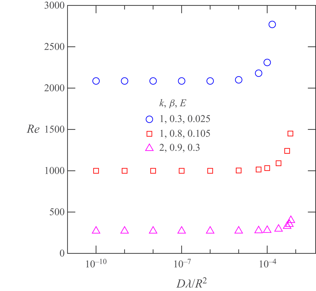
 $Sc$. In § 4.3, we show that the unstable (axisymmetric) centre mode analysed in this work is suppressed when the dimensionless diffusivity
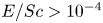 $E/Sc > 10^{-4}$, consistent with the DNS results of Sid et al. (Reference Sid, Terrapon and Dubief2018) for channel flows (although this does not rule out a subcritical transition, again involving this mode, at lower
 $Sc$).
1.5. Stability of viscoelastic shearing flows
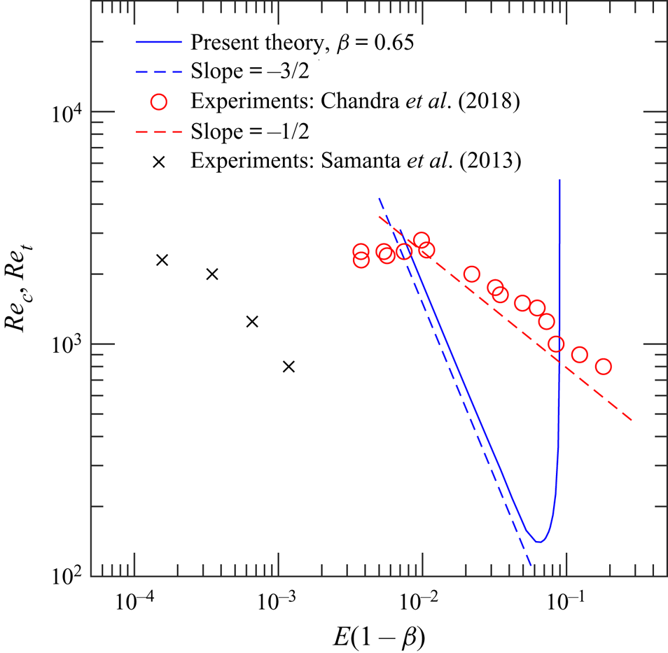
Prior to our letter (Garg et al. Reference Garg, Chaudhary, Khalid, Shankar and Subramanian2018) and the present work, there has been no attempt (barring that of Hansen (Reference Hansen1973), who neglected the convected nonlinearities in the constitutive model) to examine the linear stability of viscoelastic pipe flow, although many studies (e.g.Gorodtsov & Leonov Reference Gorodtsov and Leonov1967; Lee & Finlayson Reference Lee and Finlayson1986; Renardy & Renardy Reference Renardy and Renardy1986; Ho & Denn Reference Ho and Denn1977; Sureshkumar & Beris Reference Sureshkumar and Beris1995) have examined the stability of viscoelastic plane Couette and Poiseuille flows. A detailed survey of the literature on viscoelastic plane shearing flows has been presented in Chaudhary et al. (Reference Chaudhary, Garg, Shankar and Subramanian2019), and herein we restrict ourselves to summarizing the principal conclusions of Garg et al. (Reference Garg, Chaudhary, Khalid, Shankar and Subramanian2018). Garg et al. (Reference Garg, Chaudhary, Khalid, Shankar and Subramanian2018) showed that viscoelastic pipe flow is indeed linearly unstable in parameter regimes where experiments (Samanta et al. Reference Samanta, Dubief, Holzner, Schäfer, Morozov, Wagner and Hof2013; Chandra et al. Reference Chandra, Shankar and Das2018) observe an instability. Although the unstable mode has a finite radial spread for generic  $Re$,
 $\beta$ and
 $E$, in the asymptotic limit
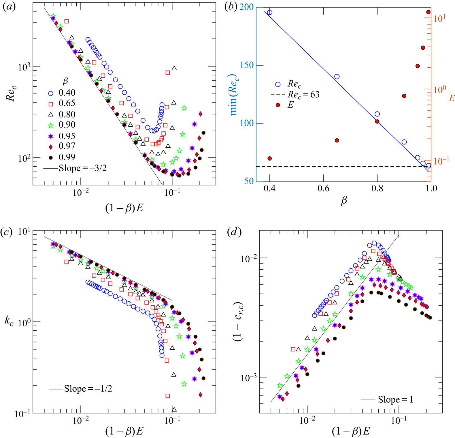
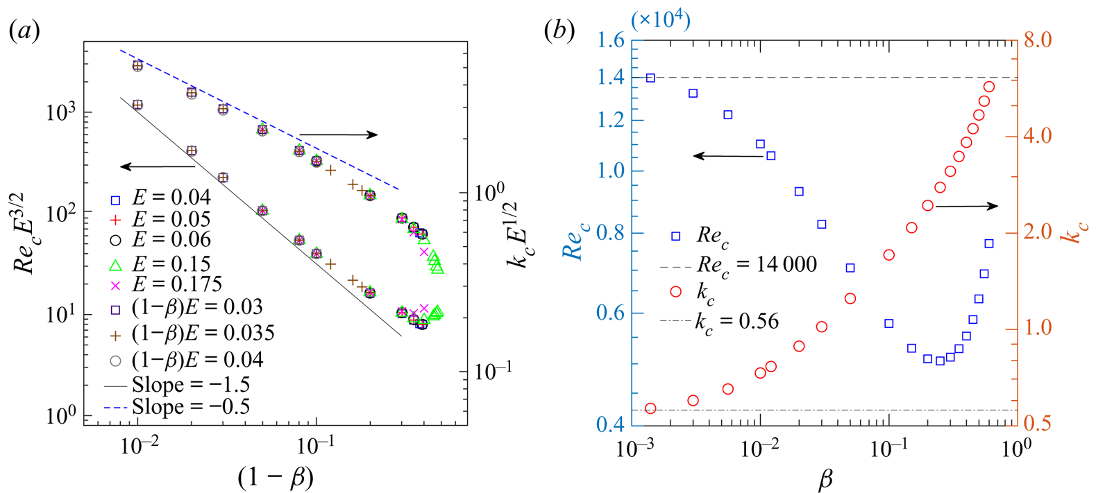
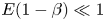 $E(1-\beta ) \ll 1$, when the critical Reynolds number required diverges as
 $Re_c \sim [E(1-\beta )]^{-3/2}$, and the critical wavenumber increases as
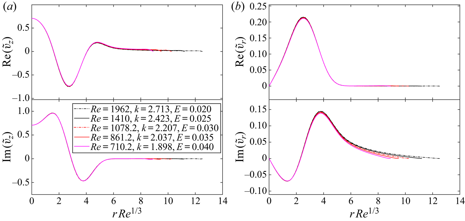
 $k_c \sim [E(1-\beta )]^{-1/2}$, the mode is confined to a thin region in the vicinity of the centreline. Regardless of localization, however, the phase speed of the unstable eigenfunction remains close to unity, indicating that the unstable mode belongs to a class of viscoelastic ‘centre modes’. The linear, elasto-inertial wall-mode instability predicted for viscoelastic channel flows in our earlier work (Chaudhary et al. Reference Chaudhary, Garg, Shankar and Subramanian2019), along with the centre-mode instability reported in Garg et al. (Reference Garg, Chaudhary, Khalid, Shankar and Subramanian2018) and expanded further in the present work, for pipe flow, show that much remains to be understood with regard to (modal) stability of viscoelastic shear flows.
1.6. Objectives of the present study
The detailed survey of the existing literature serves as a clear motivation for the work reported here, which provides a comprehensive picture of the stability of viscoelastic pipe flow using the Oldroyd-B model. The present work significantly differs from existing studies in that we analyse the linear stability of flow of dilute polymer solutions in the  $Re$–
 $W$–
 $\beta$ space, rather than along the
 $W$ or
 $Re$ axis (which amounts to the neglect of either inertia or viscoelasticity) and, importantly, for the canonical (and experimentally relevant) case of pressure-driven pipe flow. It is well established in the literature that both plane Couette and Poiseuille flows of an upper-convected Maxwell (UCM) fluid (obtained by setting
 $\beta = 0$ in the Oldroyd-B model) remain stable in the limit of zero and small
 $Re$, and during the course of this study, we have verified that pipe flow of UCM and Oldroyd-B fluids also remains stable at small
 $Re$, reinforcing the consensus that elastic effects alone may not sufficient to destabilize rectilinear viscoelastic flows.
The rest of this paper is structured as follows. In § 2, we outline the stability formulation for viscoelastic pipe Poiseuille flow subjected to infinitesimal amplitude axisymmetric disturbances; the base state and governing linearized differential equations are provided, followed by a brief description of the numerical schemes employed. In § 3, we first recapitulate the key features of the Newtonian pipe flow spectrum, which is followed by a detailed discussion of the corresponding eigenspectra for an Oldroyd-B fluid, as  $E$ is varied for fixed
 $\beta$ (§ 3.1), wherein the centre mode instability is first identified. The role of the continuous spectra (CS), in terms of their effect on the least-stable/unstable modes belonging to the Newtonian P branch, is discussed in § 3.1.1. In § 3.2, we present the viscoelastic eigenspectra for fixed
 $E$ and varying
 $\beta$, with the relation between the CS and the centre mode being discussed in § 3.2.1. The relative importance of the least-stable/unstable centre modes with regards to wall modes in viscoelastic pipe flow is highlighted in § 3.3, where we also contrast the pipe flow scenario with the recent DNS results for viscoelastic channel flow (Shekar et al. Reference Shekar, McMullen, Wang, McKeon and Graham2019), which point to the crucial role of the critical layer corresponding to the least-stable wall mode (the elastically modified TS mode). Neutral stability curves are presented in § 4, where the behaviour of the neutral curves for
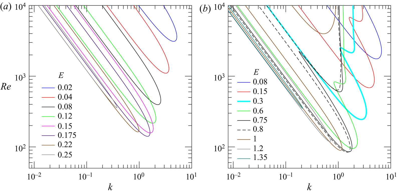
 $k\ll 1$ obtained via a low-
 $k$ asymptotic analysis is shown to agree very well with those obtained from the full governing equations for
 $k \ll 1$. For sufficiently small
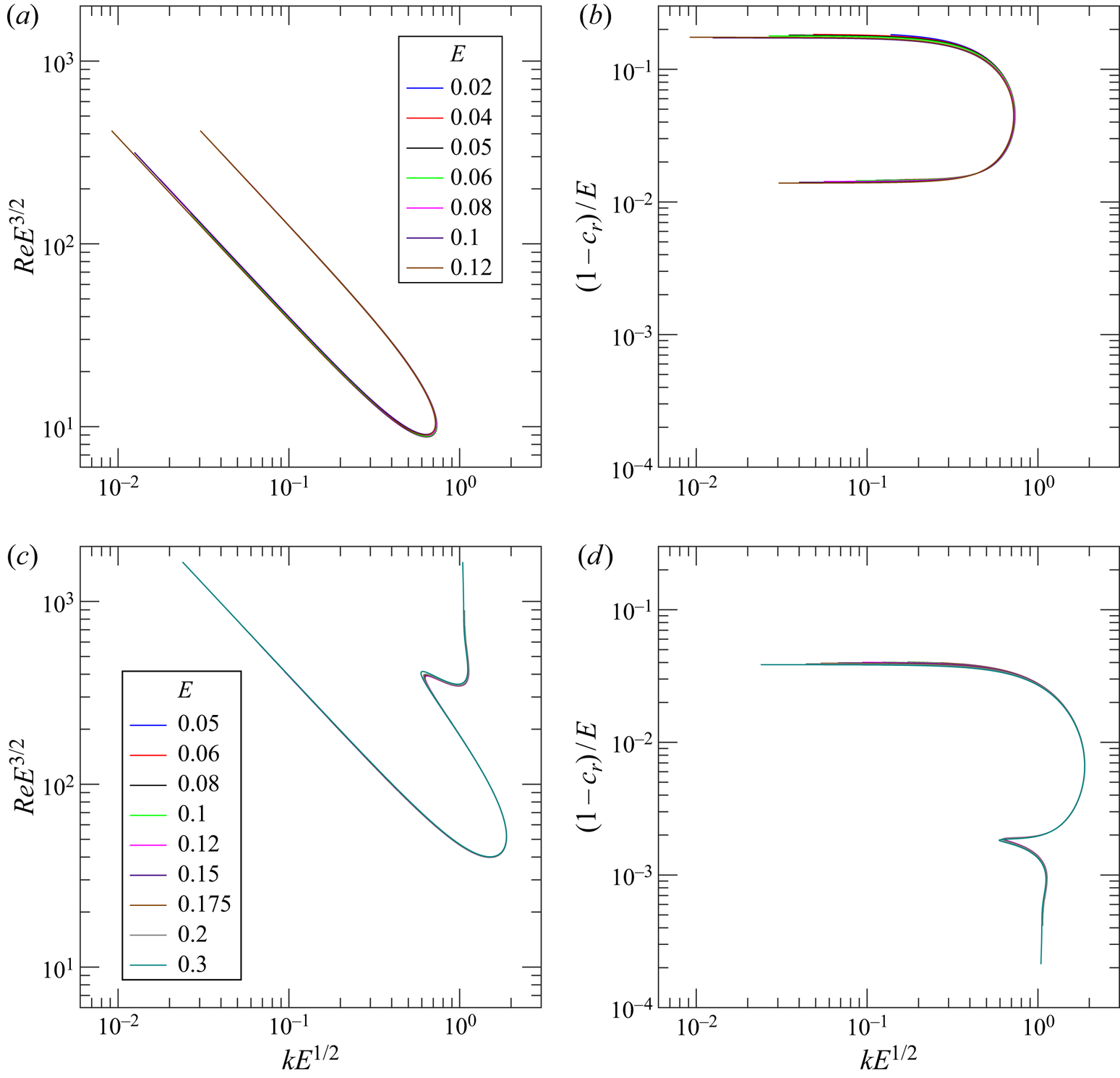
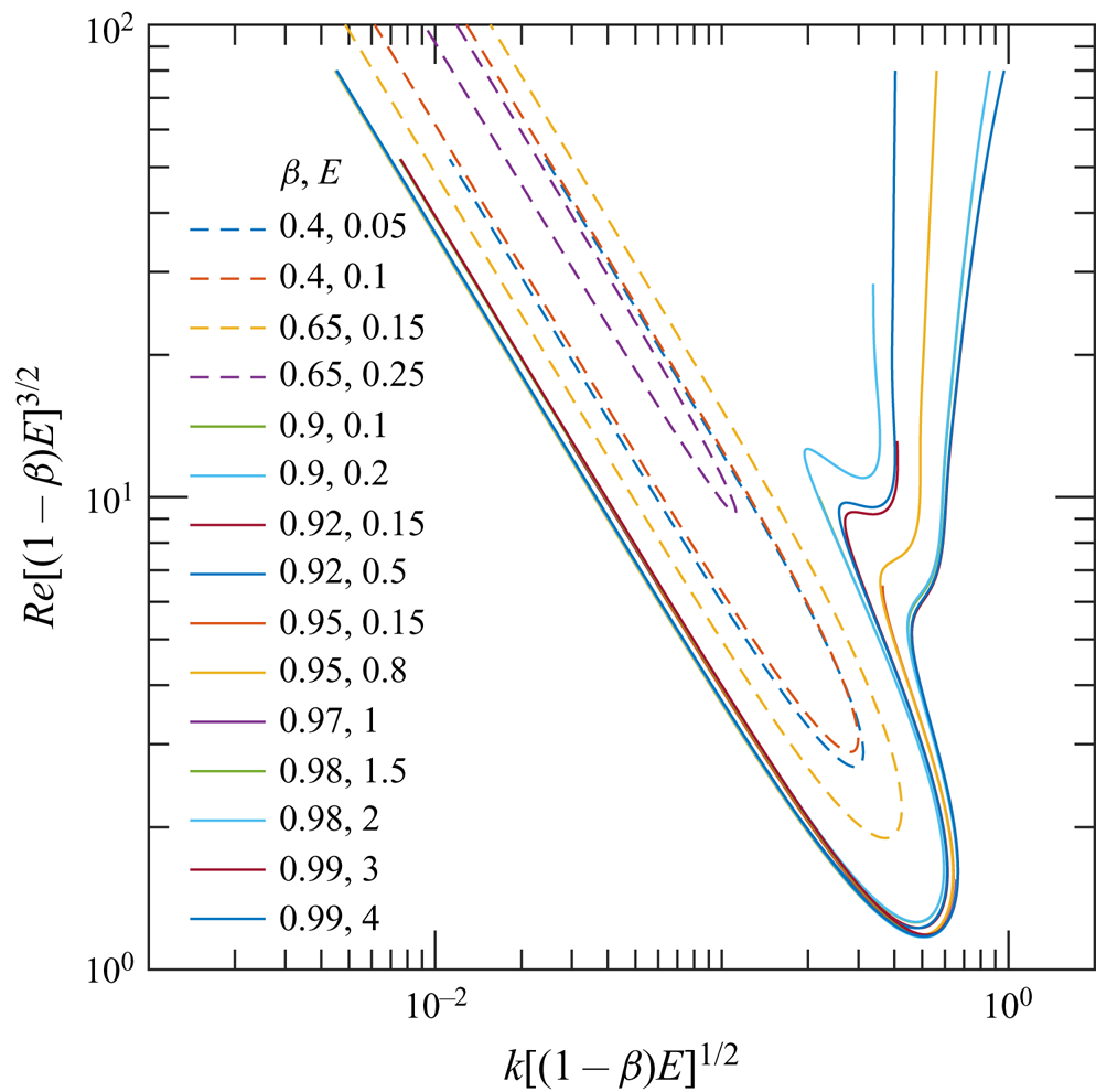
 $E$, there is a remarkable collapse of the neutral curves (§ 4.1) in the suitably rescaled
 $Re$–
 $k$ plane; a further collapse is obtained in the dual limit
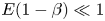 $E (1-\beta ) \ll 1$ and
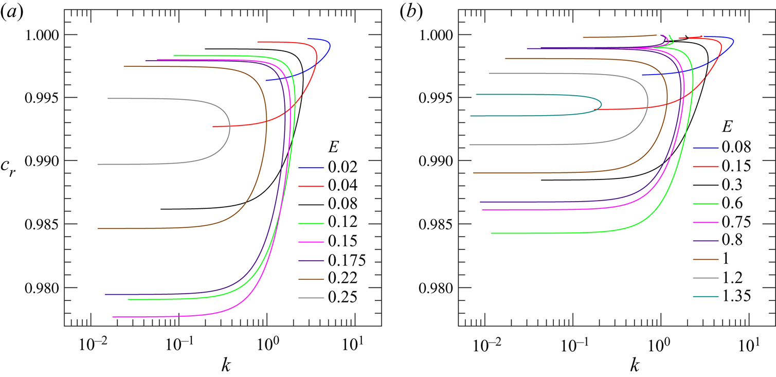
 $\beta \rightarrow 1$. In § 4.2, we demonstrate how the critical parameters
 $Re_c$,
 $k_c$ and
 $c_{r,c}$ scale with
 $E$ in the limit
 $E\ll 1$, and justify the numerical results via scaling arguments in the limit of
 $Re \gg 1$,
 $E \ll 1$, when the unstable mode is confined in the neighbourhood of the centreline. In § 4.3, we examine the role of stress diffusion in the constitutive relation to show that the unstable centre mode persists for physically realistic values of the diffusion coefficient. Our theoretical predictions are compared (in a parameter-free manner) with the experimental observations of Samanta et al. (Reference Samanta, Dubief, Holzner, Schäfer, Morozov, Wagner and Hof2013) and Chandra et al. (Reference Chandra, Shankar and Das2018) in § 4.4; herein, we also compare our predictions with the recent DNS results for viscoelastic pipe flow by Lopez et al. (Reference Lopez, Choueiri and Hof2019). Finally, in § 5, we summarize the salient findings of this study, and provide a discussion on how the discovery of a linear instability in viscoelastic pipe flow can play a pivotal role in clarifying the pathway to the MDR regime from the laminar state.
2. Problem formulation and numerical method
2.1. Governing equations
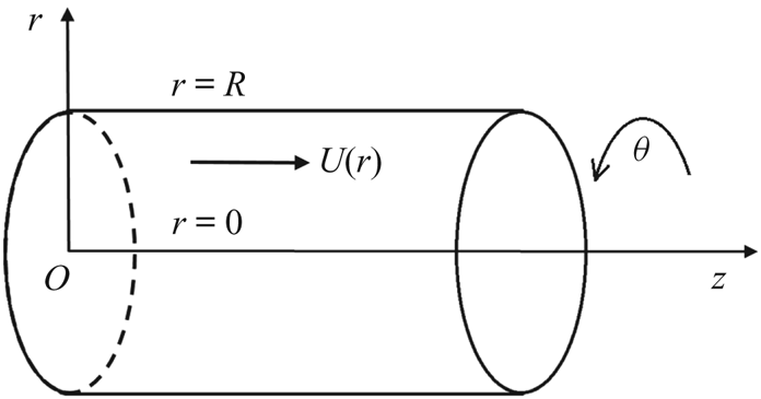
We consider the linear stability of steady fully developed flow of a viscoelastic fluid in a rigid circular pipe of radius  $R$ as shown in figure 1. A cylindrical polar coordinate system is used with
 $r$,
 $\theta$ and
 $z$ denoting the radial, azimuthal and axial directions, respectively. The following scales are used for non-dimensionalizing the governing equations: radius of the pipe
 $R$ for lengths, maximum base-flow velocity
 $U_{max}$ for velocities,
 $R/U_{max}$ for time and
 $\rho U_{max}^2$ for pressure and stresses, with
 $\rho$ being the density of the fluid.
Schematic diagram showing the geometry and the coordinate system considered.

The governing (non-dimensional) continuity and Cauchy momentum equations are given by
 \begin{equation} \boldsymbol{\nabla} \boldsymbol{\cdot} \boldsymbol{v} = 0, \quad \frac{{\partial} \boldsymbol{v}}{{\partial} t} + (\boldsymbol{v} \boldsymbol{\cdot} \boldsymbol{\nabla}) \boldsymbol{v} ={-}\boldsymbol{\nabla} p +\frac{\beta}{Re}\nabla^2\boldsymbol{v} + \boldsymbol{\nabla}\boldsymbol{\cdot}{\boldsymbol{\mathsf{T}}}. \end{equation}
Here,  $\boldsymbol {v}$ is the fluid velocity field,
 $p$ is the pressure field and
 ${\boldsymbol{\mathsf{T}}}$ is the polymeric contribution to the stress tensor, which in turn is given by the Oldroyd-B constitutive relation (Larson Reference Larson1988) as follows:
 \begin{equation} W \left(\frac{{\partial} {\boldsymbol{\mathsf{T}}}}{{\partial} t}+\left( \boldsymbol{v} \boldsymbol{\cdot} \boldsymbol{\nabla} \right){\boldsymbol{\mathsf{T}}}-{\boldsymbol{\mathsf{T}}} \boldsymbol{\cdot} \left(\boldsymbol{\nabla} \boldsymbol{v}\right) -\left(\boldsymbol{\nabla} \boldsymbol{v} \right)^{\textrm{T}} \boldsymbol{\cdot}{\boldsymbol{\mathsf{T}}}\right) +{\boldsymbol{\mathsf{T}}} = \frac{(1-\beta)}{Re} \{\boldsymbol{\nabla}\boldsymbol{v}+(\boldsymbol{\nabla}\boldsymbol{v})^\textrm{T}\}. \end{equation}
The solvent to solution viscosity ratio is denoted by  $\beta = \eta _s/\eta$, where the solution viscosity is
 $\eta = \eta _p + \eta _s$,
 $\eta _s$ and
 $\eta _p$ being the solvent and polymer viscosities, respectively;
 $\beta = 0$ and
 $1$ denote the UCM and Newtonian limits. For a fixed
 $\beta$, the dimensionless groups relevant to the stability of the Oldroyd-B fluid described previously are the Reynolds number
 $Re=\rho U_{max} R/\eta$ and the Weissenberg number
 $W=\lambda U_{max} /R$, which is a ratio of the polymer relaxation time
 $\lambda$ to the flow time scale. The Oldroyd-B model describes the stress in a dilute solution of polymer chains modelled as non-interacting Hookean dumbbells (Larson Reference Larson1988), and is invariably the first model used in the examination of elastic phenomena involving dilute polymer solutions. Consistent with the aforementioned microscopic picture, the Oldroyd-B model assumes the relaxation time to be independent of both the shear rate and the polymer concentration. As the model predicts a shear-rate-independent viscosity, the non-Newtonian (elastic) effects in this model arise from an effective tension along the streamlines (arising from flow-aligned dumbbells), which manifests as a shear-rate-independent first normal stress different in viscometric flows. This model has been used extensively, and with considerable success, in earlier investigations of inertialess elastic instabilities in flows with curved streamlines (Larson, Shaqfeh & Muller Reference Larson, Shaqfeh and Muller1990; Pakdel & McKinley Reference Pakdel and McKinley1996; Shaqfeh Reference Shaqfeh1996). The so-called Boger fluids constitute an experimental realization of this constitutive model (Boger & Nguyen Reference Boger and Nguyen1978). As discussed later in the manuscript (in § 4.4.1, where we use scaling arguments in the context of the FENE-P model to assess the role of shear thinning), whereas shear thinning can play an important role especially in flow through microtubes (Samanta et al. Reference Samanta, Dubief, Holzner, Schäfer, Morozov, Wagner and Hof2013; Chandra et al. Reference Chandra, Shankar and Das2018), the Oldroyd-B model does have the necessary ingredients to qualitatively predict the instabilities observed in experiments.
2.2. Base state
The base-state velocity profile is the classical Hagen–Poiseuille profile because the nonlinear terms in the upper-convected derivative of the polymer shear stress  $T_{rz}$ are identically zero. The non-dimensional base flow velocity vector is given by
 \begin{equation} \bar{\boldsymbol{v}} = \begin{bmatrix} \bar{v}_{r}\\ 0\\ \bar{v}_{z} \end{bmatrix}= \begin{bmatrix} 0\\0\\U(r)\end{bmatrix}, \end{equation}
where 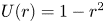 $U(r)=1-r^2$ for pipe Poiseuille flow. Here, and in what follows, base state quantities are denoted by an overbar. The polymer contribution to the stress tensor in the base state is given by
 \begin{equation} \bar{{\boldsymbol{\mathsf{T}}}}=\begin{bmatrix} \bar{\tau}_{rr} & 0 & \bar{\tau}_{rz}\\ 0 & \bar{\tau}_{\theta\theta} & 0\\ \bar{\tau}_{zr} & 0 & \bar{\tau}_{zz}\end{bmatrix}= \frac{(1-\beta)}{Re} \begin{bmatrix} 0 & 0 & U'\\ 0 & 0 & 0\\ U' & 0 & 2WU'^2\end{bmatrix},\end{equation}
where,  $f'\equiv \mathrm {D}f \equiv {\mathrm {d}f}/{\mathrm {d}r}$. Unlike the velocity profile, the base-state stress profile differs from that of a Newtonian fluid in having a tension along the streamlines proportional to the square of the velocity gradient.
2.3. Linear stability analysis
A temporal linear stability analysis is carried out wherein the base-state described previously is subjected to small-amplitude axisymmetric perturbations. Owing to the absence of a Squire-like theorem for pipe flow even in the simpler Newtonian case, in general, both axisymmetric and non-axisymmetric disturbances need to be considered for viscoelastic Oldroyd-B fluids. However, for the parameter regime probed in this study, we find axisymmetric disturbances alone to be unstable, and this study is therefore restricted to axisymmetric disturbances. The total velocity, pressure and stress are expressed in terms of their base-state values and perturbations as
 \begin{gather} \boldsymbol{v} = \boldsymbol{\bar{v}} + \boldsymbol{\hat{v}}, \end{gather}
 \begin{gather}p = \bar{p} + \hat{p}, \end{gather}
 \begin{gather}{\boldsymbol{\mathsf{T}}} = \bar{{\boldsymbol{\mathsf{T}}}} + \hat{{\boldsymbol{\mathsf{T}}}}, \end{gather}
with  $\hat {f}$ denoting the perturbation to the dynamical quantity
 $f$. For axisymmetric disturbances without swirl (i.e.
 $\hat {v}_{\theta } = 0$), the perturbation velocity and stress tensor are
 \begin{equation} \hat{\boldsymbol{v}}= \begin{bmatrix} \hat{v}_{r}\\ 0\\ \hat{v}_{z} \end{bmatrix},\quad \text{and}\quad \hat{{\boldsymbol{\mathsf{T}}}}= \begin{bmatrix} \hat{\tau}_{rr} & 0 & \hat{\tau}_{rz}\\ 0 & \hat{\tau}_{\theta\theta} & 0\\ \hat{\tau}_{zr} & 0 & \hat{\tau}_{zz} \end{bmatrix}. \end{equation}
Next, the perturbation quantities above are represented in the form of Fourier modes in the axial ( $z$) direction in the following manner:
 \begin{equation} \hat{f}(r,z;t) = \tilde{f}(r)\mathrm \exp\{\mathrm{i}k (z - c t)\}, \end{equation}
where  $k$ is the axial wavenumber and
 $c = c_r + i c_i$ is the complex wave speed. The flow is temporally unstable (stable) if
 $c_i > 0$
 $(< 0)$. Substituting (2.7) in the linearized versions of (2.1a,b)–(2.2), we obtain the following set of linearized governing equations:
 \begin{gather} \left(\mathrm{D} + \frac{1}{r}\right)\tilde v_{r}+\mathrm{i} k\tilde v _{z}=0, \end{gather}
 \begin{gather}G \tilde{v}_r ={-}\mathrm{D}\tilde{p} + \left[\left(\mathrm{D}+\frac{1}{r}\right)\tilde{\tau}_{rr}+\mathrm{i}k\tilde{\tau}_{rz}-\frac{\tilde{\tau}_{\theta\theta}}{r}\right] + \frac{\beta}{Re}\mathrm{L}\tilde{v}_r, \end{gather}
 \begin{gather}G \tilde{v}_z +U'\tilde{v}_r={-}\mathrm{i}k\tilde{p} + \left[\left(\mathrm{D}+\frac{1}{r}\right)\tilde{\tau}_{rz}+\mathrm{i}k\tilde{\tau}_{zz}\right] + \frac{\beta}{Re}\left(\mathrm{L}+\frac{1}{r^2}\right)\tilde{v}_z, \end{gather}
 \begin{gather}H\tilde{\tau}_{rr}=2\frac{(1-\beta)}{Re}\left(\mathrm{D}+W\mathrm{i}kU'\right)\tilde{v}_r, \end{gather}
 \begin{gather} H\tilde{\tau}_{rz}-WU'\tilde{\tau}_{rr} = \frac{(1-\beta)}{Re} [\{\mathrm{i}k-W(U''-U'\mathrm{D}-2\mathrm{i}kWU'^2)\} \tilde{v}_r +(\mathrm{D}+W\mathrm{i}kU')\tilde{v}_z ], \end{gather}
 \begin{gather} H\tilde{\tau}_{\theta\theta} = 2\frac{(1-\beta)}{Re} \frac{\tilde{v}_r}{r}, \end{gather}
 \begin{gather}H\tilde{\tau}_{zz}-2WU'\tilde{\tau}_{rz} = 2\frac{(1-\beta)}{Re} \left[{-}2W^2U'U'' \tilde{v}_r +\{\mathrm{i}k+WU'\left(\mathrm{D}+2W\mathrm{i}kU'\right)\}\tilde{v}_z\right], \end{gather}
where  $G = \mathrm {i}k(U-c)$,
 $H = 1 + WG$ and
 $\mathrm {L} = (\mathrm {D}^2 + {\mathrm {D}}/{r}-{1}/{r^2}-k^2)$. The no-slip boundary conditions
 $\tilde {v}_r = 0$ and
 $\tilde {v}_{z} = 0$ are applicable at
 $r = 1$, whereas at
 $r = 0$, the conditions
 $\tilde {v}_r = 0$ and
 $\tilde {v}_{z} = \text {finite}$, corresponding to regularity of axisymmetric disturbances in the vicinity of the centreline, are used (Batchelor & Gill Reference Batchelor and Gill1962; Khorrami, Malik & Ash Reference Khorrami, Malik and Ash1989).
2.4. Numerical method
We use two independent formulations to solve the viscoelastic eigenvalue problem for the wavespeed  $c$. In the first, the governing equations for perturbation stresses (2.11)–(2.14) are substituted in (2.9)–(2.10) to obtain two linearized ordinary differential equations corresponding to the momentum balances in
 $r$- and
 $z$-directions in addition to (2.8), and the dependent variables in this formulation are
 $\tilde {v}_r$,
 $\tilde {v}_z$ and
 $\tilde {p}$. In the second formulation, we directly solve the system of linear equations (2.8)–(2.14), with
 $\tilde {v}_r/r$ as the dependent variable instead of
 $\tilde {v}_r$, with the other variables being
 $\tilde {v}_z$,
 $\tilde {p}$,
 $\tilde {\tau }_{\theta \theta }$,
 $\tilde {\tau }_{rr}$,
 $\tilde {\tau }_{rz}$ and
 $\tilde {\tau }_{zz}$. The simplified equations represent a homogeneous eigenvalue problem, and are solved using the standard spectral collocation numerical scheme based on Chebyshev polynomials (Boyd Reference Boyd2000; Trefethen Reference Trefethen2000). Results from the two different spectral approaches show excellent agreement. Further, the eigenvalues obtained from the spectral method were verified using a shooting method (Ho & Denn Reference Ho and Denn1977; Lee & Finlayson Reference Lee and Finlayson1986) implemented for the first formulation, based on an adaptive step size Runge–Kutta integrator and a Newton–Raphson procedure for determining the eigenvalue. The integration for the shooting method was carried out from a point near the centreline
 $r = \epsilon$ (with
 $\epsilon \rightarrow 0$) to the pipe wall at
 $r = 1$. The velocities at
 $r = \epsilon$ were obtained using a Frobenius series expansion (Garg & Rouleau Reference Garg and Rouleau1972) about the regular singular point
 $r = 0$. The shooting method gives very accurate (based on our choice of tolerance, typically
 $10^{-9}$) results when sufficiently close initial guesses are provided, whereas the number of polynomials
 $N$ required for convergence of eigenvalues in the spectral method depends mainly on the nature of the eigensolutions and the parameter values. Typically, the
 $N$ required for convergence of eigenvalues for finite
 $\beta$ is in the range
 $150$–
 $200$, whereas that for the UCM limit (
 $\beta \rightarrow 0$) is in the range
 $400$–
 $500$. There is no prior literature that reports the eigenspectrum for pipe flow of an Oldroyd-B fluid, and hence our numerical procedure was benchmarked in the Newtonian limit (obtained by setting
 $W = 0$ or
 $\beta = 1$). Results in this limit are available, for instance, in Schmid & Henningson (Reference Schmid and Henningson1994, Reference Schmid and Henningson2001).
3. General features of the viscoelastic pipe flow eigenspectrum
We first discuss results obtained for pipe Poiseuille flow of Oldroyd-B fluids, with the extensive aid of eigenspectra, and demonstrate how the viscoelastic spectrum differs substantially from its Newtonian counterpart. Sections 3.1 and 3.2, respectively, consider the variation in the eigenspectrum with increasing  $E$ (from zero) at a fixed
 $\beta$, and with variation in
 $\beta$ at a fixed
 $E$. The focus is on the locations of the least-stable modes, and as to how they change with changing
 $E$ and
 $\beta$. Alongside, we also demonstrate (§§ 3.1.1 and 3.2.1) how the CS play an important role in the emergence of the eigenmode (a centre mode) that eventually becomes unstable. In § 3.3, we contrast the nature of the least-stable modes in viscoelastic pipe and channel flows, showing, in particular, that for the parameters corresponding to viscoelastic channel flow where the wall (TS) mode is least stable (Shekar et al. Reference Shekar, McMullen, Wang, McKeon and Graham2019), pipe flow has the centre mode as its least-stable mode. The centre mode instability is characterized further using neutral stability curves in the
 $Re$–
 $k$ plane at fixed
 $E$ and
 $\beta$ (§ 4), which are shown to collapse when plotted using suitable rescaled variables (§ 4.1). The variation of the minima of the
 $Re$–
 $k$ neutral curves (the critical Reynolds number
 $Re_c$) and the corresponding critical wavenumber
 $k_c$ is explored (§ 4.2) for different
 $E$ and
 $\beta$, and scaling relationships are obtained in the limit
 $E \ll 1$ and
 $E \ll 1$,
 $(1-\beta ) \ll 1$. It is then shown that the scaling results inferred from the numerics are consistent with those obtained from a boundary-layer analysis near the pipe centreline. We finally compare our theoretical predictions with recent experimental and DNS studies in § 4.4.
3.1. Spectra at fixed  $\beta$ and different $E$


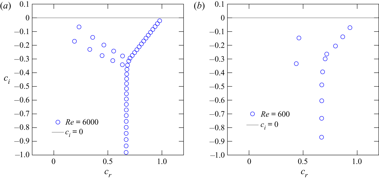
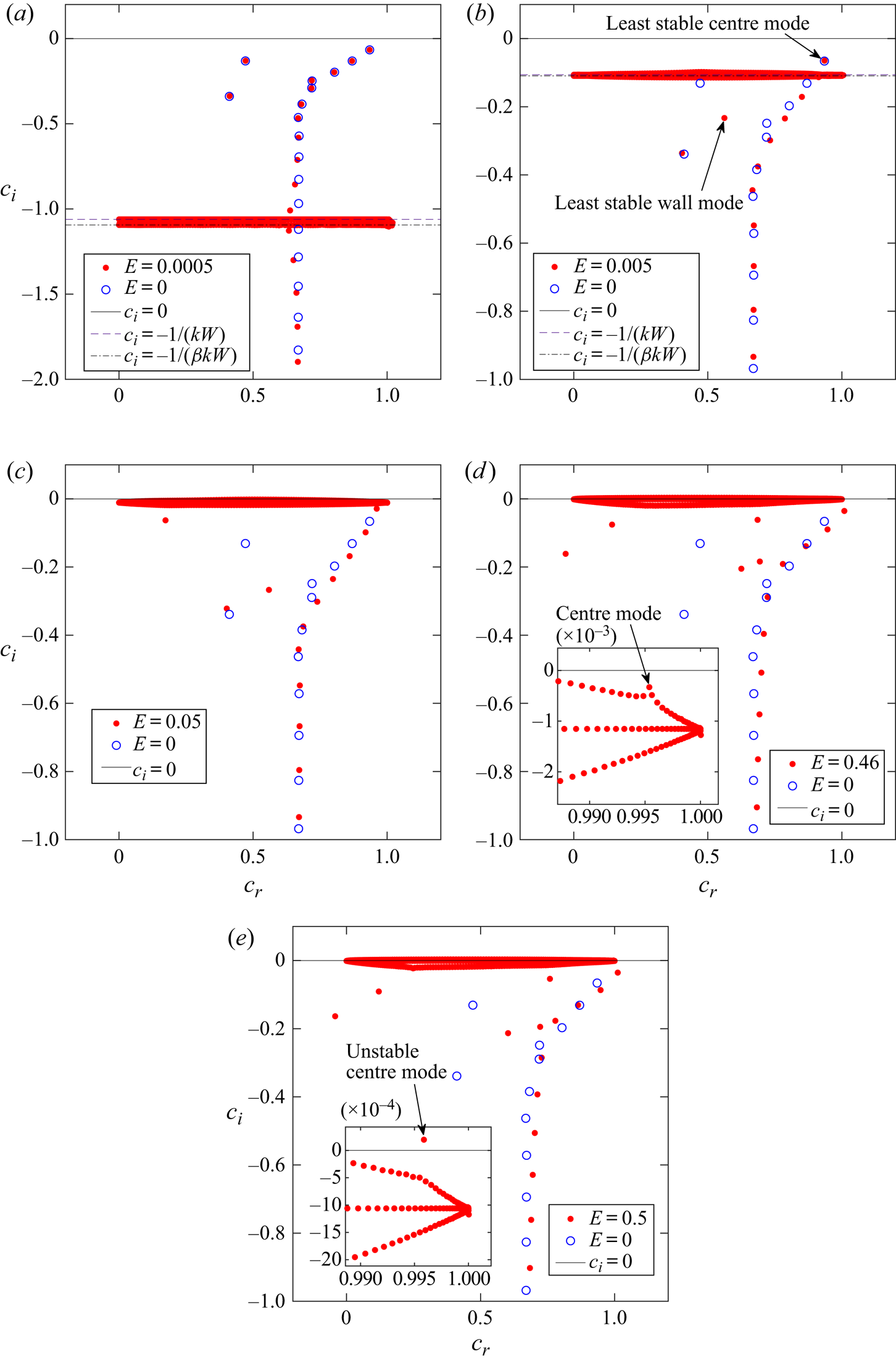
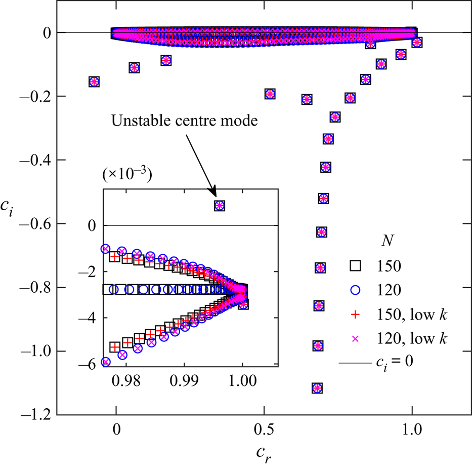
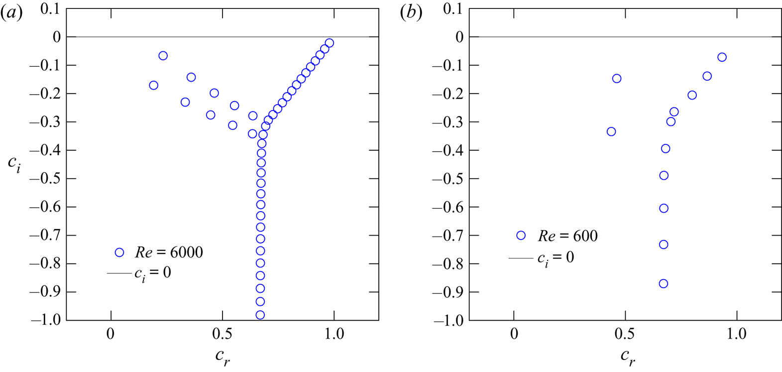
Figures 2(a) and 2(b) show the eigenspectra for Newtonian pipe flow at  $Re = 6000$ and
 $Re = 600$, respectively. The spectrum has the well-known ‘Y’-shaped structure (Mack Reference Mack1976; Schmid & Henningson Reference Schmid and Henningson2001) at
 $Re = 6000$, but this is only beginning to form in the spectrum at
 $Re = 600$. The Y-shaped structure is composed of three branches: (i) the ‘A branch’ corresponding to ‘wall modes’ with
 $c_r \rightarrow 0$ for
 $Re \gg 1$ on the top left; (ii) the ‘P branch’ that consists ‘centre modes’ with
 $c_r \rightarrow 1$ for
 $Re \gg 1$ on the top right and (iii) the ‘S branch’ that consists modes with
 $c_r \approx 2/3$ extending down to
 $c_i = -\infty$. For
 $Re \gg 1$, the decay rates of the least-stable centre and wall modes vary as
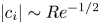 $|c_i| \sim Re^{-1/2}$ and
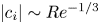 $|c_i| \sim Re^{-1/3}$, respectively (Meseguer & Trefethen Reference Meseguer and Trefethen2003), implying that the centre modes are the least stable at large
 $Re$. Although these scalings need not necessarily hold for the moderate
 $Re$ (
 $= 600$) considered in figures 3 and 4, the centre mode is nevertheless found to be the least stable. Consistent with previous studies (Schmid & Henningson Reference Schmid and Henningson1994, Reference Schmid and Henningson2001), all modes for Newtonian pipe flow are found to be stable. We discuss the nature of the least-stable mode in more detail in § 3.3.
The ‘Y’-shaped eigenspectrum for Newtonian pipe flow subjected to axisymmetric disturbances for  $k = 3$, and for (a)
 $Re = 6000$ and (b)
 $Re = 600$.
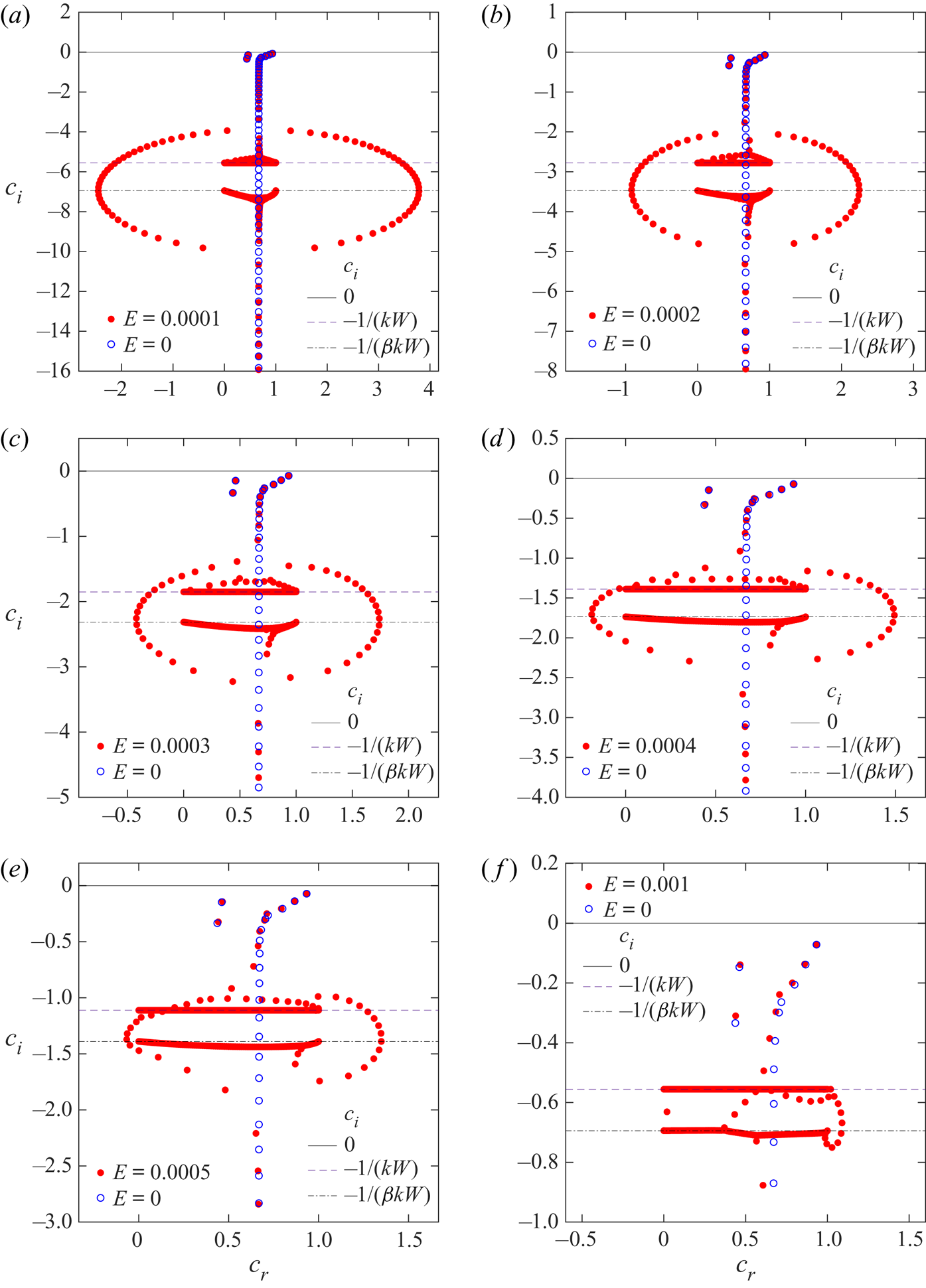
Eigenspectra for pipe flow of an Oldroyd-B fluid at  $\beta = 0.8$,
 $Re = 600$ and
 $k = 3$, and for different
 $E$ in the range
 $5 \times 10^{-4}$–
 $10^{-3}$: (a)
 $E = 10^{-4}$; (b)
 $E = 2\times 10^{-4}$; (c)
 $E = 3\times 10^{-4}$; (d)
 $E = 4\times 10^{-4}$; (e)
 $E = 5\times 10^{-4}$ and (f)
 $E = 10^{-3}$. The eigenspectra are obtained for
 $N=200$, and there is excellent convergence of the spectra for
 $N=200$ and
 $250$ (not shown). An elliptical-ring structure is prominent at the lower
 $E$, but is absent beyond
 $E = 10^{-3}$. The vertical locations of the CS1 and CS2 lines and the Newtonian spectrum for the same
 $Re$ and
 $k$ are shown for reference.

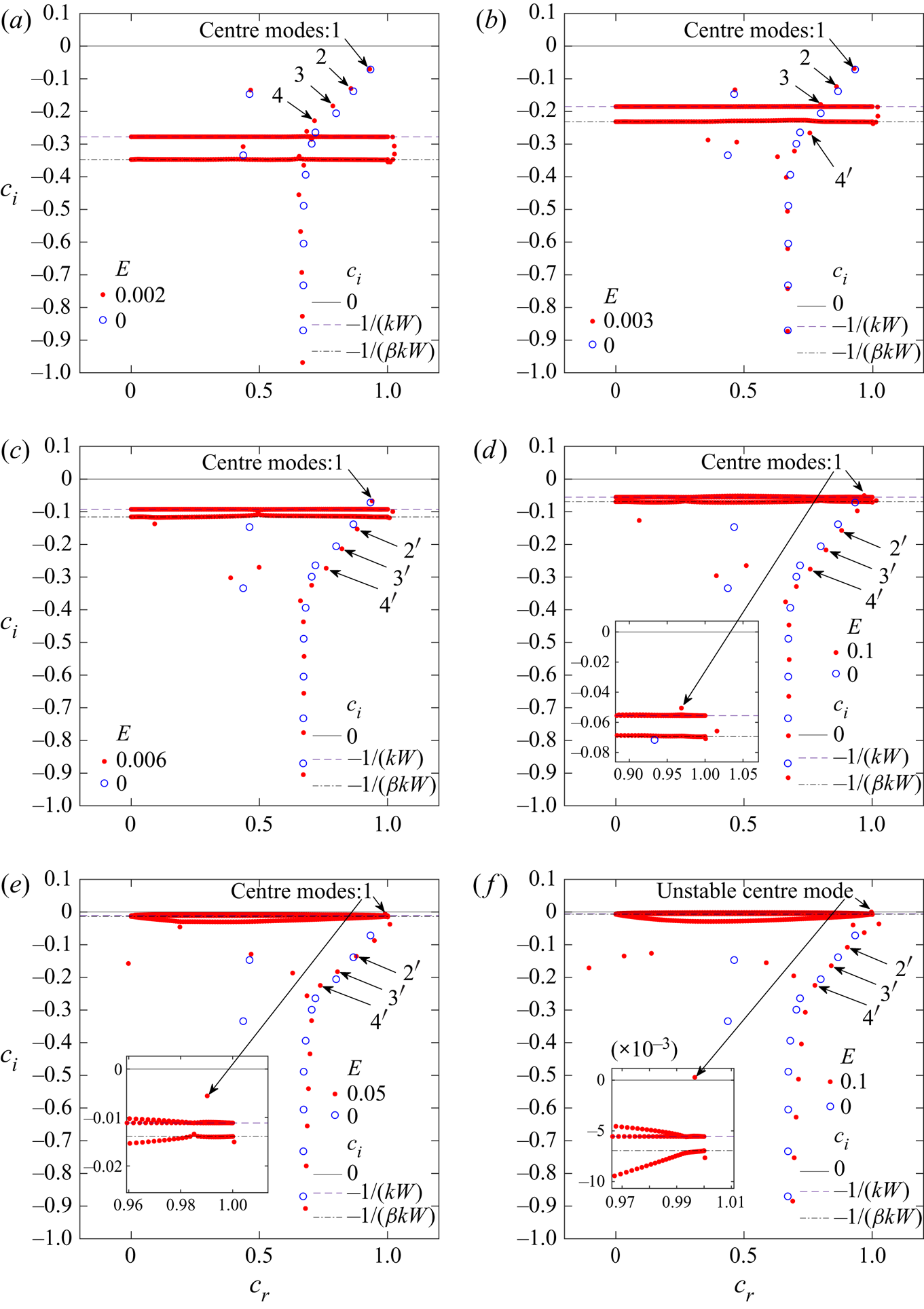
Eigenspectra for the Oldroyd-B fluid for different  $E$ in the range
 $0.002$–
 $0.1$, at
 $\beta = 0.8$,
 $Re = 600$,
 $N = 200$ and
 $k = 3$: (a)
 $E = 0.002$; (b)
 $E = 0.003$; (c)
 $E = 0.006$; (d)
 $E = 0.01$; (e)
 $E = 0.05$ and (f)
 $E = 0.1$. The spectra, shown for a narrower range of
 $c_r$ and
 $c_i$ compared with figure 3, demonstrate how the discrete centre modes (labelled
 $2$,
 $3$ and
 $4$) merge into and emerge out (labelled
 $2'$,
 $3'$ and
 $4'$) of the CS as
 $E$ is increased. The least-stable centre mode (labelled 1) always stays above the CS, and eventually becomes unstable at
 $E = 0.1$. The vertical locations of the CS lines and the Newtonian spectrum at the same
 $Re$ and
 $k$ are shown for reference.

The spectra for pipe flow of an Oldroyd-B fluid reduce to the Newtonian one either when  $E \rightarrow 0$ (at fixed
 $\beta$) or when
 $\beta \rightarrow 1$ (at fixed
 $E$). We therefore first examine the effect of viscoelasticity as
 $E$ is increased from zero, with
 $\beta$ fixed at
 $0.8$. Figures 3 and 4 show the viscoelastic eigenspectra for
 $Re =600$, with
 $E$ ranging from
 $5 \times 10^{-4}$ to
 $0.1$. The values of
 $\beta$ and
 $Re$ are chosen so they are close to the experimental conditions of Samanta et al. (Reference Samanta, Dubief, Holzner, Schäfer, Morozov, Wagner and Hof2013) and our earlier theoretical work (Garg et al. Reference Garg, Chaudhary, Khalid, Shankar and Subramanian2018). With increasing
 $E$, figures 3 and 4 show the classical Y-shaped structure of the Newtonian spectrum to be altered by elasticity in a singular manner. There are important differences between the two spectra even for the smallest
 $E$, the most prominent of these being the appearance of two CS for the viscoelastic case, similar to viscoelastic plane shear flows (Renardy & Renardy Reference Renardy and Renardy1986; Sureshkumar & Beris Reference Sureshkumar and Beris1995; Graham Reference Graham1998; Wilson, Renardy & Renardy Reference Wilson, Renardy and Renardy1999; Grillet et al. Reference Grillet, Bogaerds, Peters and Baaijens2002; Chokshi & Kumaran Reference Chokshi and Kumaran2009). It is now well understood (Graham Reference Graham1998; Chaudhary et al. Reference Chaudhary, Garg, Shankar and Subramanian2019; Subramanian, Reddy & Roy Reference Subramanian, Reddy and Roy2020) that the CS arise from the local nature of the constitutive model for the polymeric stress, and disappear when non-local diffusive effects are incorporated in the constitutive relation (see § 4.3). The eigenvalues corresponding to the CS are obtained by setting to zero the coefficient of the highest-order derivative in the differential equation governing the stability. This coefficient turns out to be the product
 $[1 + \mathrm {i}kW(U-c)] [1 + \beta \mathrm {i}kW(U-c)]$, which leads to a pair of horizontal ‘lines’ in the
 $c_r$–
 $c_i$ plane with
 $c_i = -1/(kW)$ and
 $c_i = -1/(\beta k W)$, and with
 $0 \leq c_r \leq 1$. Henceforth, these two CS are respectively abbreviated as ‘CS1’ and ‘CS2’ respectively, with CS1 being present even in the limit of a UCM fluid, and CS2 being present only when there is a solvent contribution (
 $\beta \neq 0$), receding to
 $c_i = -\infty$ in the limit
 $\beta \rightarrow 0$.
Figure 3 explores the spectra for the smallest  $E$ (ranging from
 $10^{-4}$ to
 $10^{-3}$), the range of
 $c_r$ and
 $c_i$ being chosen so as to provide a larger view of the spectra. Here, in addition to the modified Y-shaped structure of the Newtonian spectra and the two CS lines, there exist a class of modes that form a ‘ring’ that surrounds the CS at small
 $E$ of
 $O(\sim 10^{-4})$. Similar to CS1 and CS2 , all modes belonging to the ring structure are stable for the range of
 $E$ explored. For small
 $E$, the modes on the ring appear to be symmetrically distributed (figures 3a to 3c) about the S branch, forming an approximate ellipse. As
 $E$ is increased, the modes move towards the CS with the ring decreasing in size. For
 $E = 4\times 10^{-4}$, these modes move closer, intermingling with the other modes that emerge from the CS (figure 3d), and the ring structure is now fully distorted. At still higher
 $E\sim 10^{-3}$ (see figures 3e and 3f), the modes originally on the ring collapse, wrapping around the CS in an irregular manner. To understand the origin of the ring structure, it is relevant to recall a prominent feature of the viscoelastic spectra (at non-zero
 $Re$) in the UCM limit (
 $\beta = 0$): an infinite sequence of discrete modes corresponding to damped shear waves in a viscoelastic fluid (discussed in § 3.2), and are referred to as the high-frequency Gorodtsov–Leonov (‘HFGL’) modes (Gorodtsov & Leonov Reference Gorodtsov and Leonov1967; Kumar & Shankar Reference Kumar and Shankar2005; Chaudhary et al. Reference Chaudhary, Garg, Shankar and Subramanian2019). This sequence corresponds to
 $c_i = -1/(2kW)$, and extends to infinity in either direction parallel to the
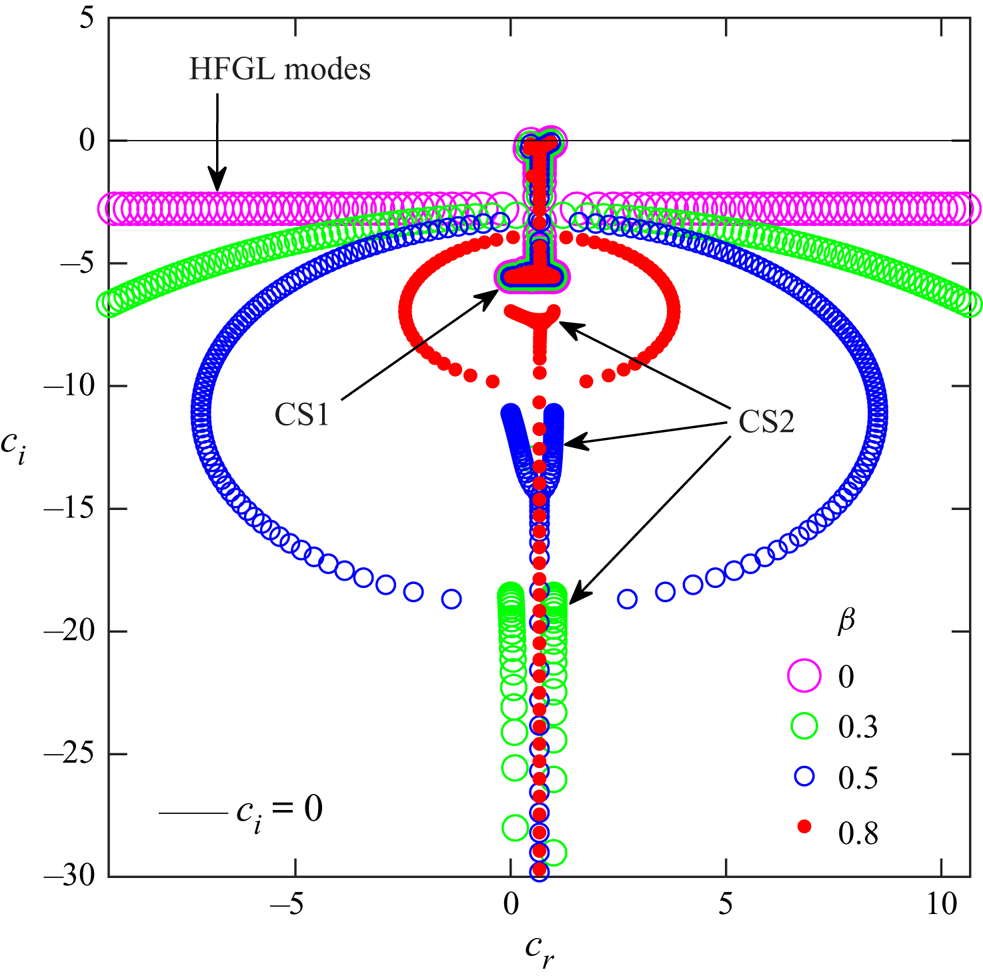
 $c_r$ axis. As we demonstrate in figure 10, at any finite
 $\beta$, the infinite-in-extent HFGL line curves downwards, eventually meeting the S branch, and thereby leading to the aforementioned ring structure for sufficiently small
 $E$.
In figure 4, we explore the spectra for larger  $E$, in the range
 $0.002$–
 $0.1$, with the ranges of
 $c_r$ and
 $c_i$ being chosen to provide a more magnified view of the spectra. As
 $E$ is increased, the vertical locations of the two CS move up towards
 $c_i = 0$, and in the process, the discrete ‘elastic’ centre modes (labelled 2, 3 and 4 in figure 4a; and that lie above the CS) disappear into the CS. As
 $E$ is increased further, new discrete elastic centre modes (now shown with the labels
 $2'$,
 $3'$ and
 $4'$ in figures 4c and 4d, which lie below the CS) emerge out of the CS. The labelling of the modes that emerge below the CS are for the purposes of reference only, and there is no connection between these modes (with primes) and those (without primes) that disappeared into the CS. This was ascertained from the absence of any resemblance between the eigenfunctions of the modes that disappear into and reappear from the CS. A more detailed account of the evolution of the centre modes as
 $E$ is varied is provided in figure 7. Importantly, the least-stable centre mode (labelled 1) does not merge into the CS, and always stays above it. As
 $E$ is increased to
 $0.1$, this centre mode becomes unstable, and corresponds to the instability first reported by Garg et al. (Reference Garg, Chaudhary, Khalid, Shankar and Subramanian2018). This scenario of the unstable centre mode being a smooth continuation of its stable Newtonian counterpart is, however, sensitive to
 $\beta$, and we show (and provide further details in § 3.1.1) that there exist other parameter regimes where the centre mode that eventually becomes unstable emerges out the CS with increasing
 $E$, and there is no connection to the least-stable Newtonian centre mode. Other new stable centre modes (with
 $c_r \rightarrow 1$; see figures 4d–4f) and wall modes (with
 $c_r \rightarrow 0$, and even negative; see figures 4e and 4f), which have no Newtonian counterparts, appear below the CS with increasing
 $E$. Increase in
 $E$ has a stabilizing effect on these modes. The aforementioned annihilation and creation of discrete modes with increase in
 $E$ occurs because both the CS are branch cuts (Wilson et al. Reference Wilson, Renardy and Renardy1999) for Poiseuille flow. Note that, for plane Couette flow, only CS2 is a branch cut. It is well known that discrete eigenmodes can appear or disappear out of the branch cut as parameters are varied, and this aspect is discussed further in § 3.1.1 in the specific context of the centre mode.
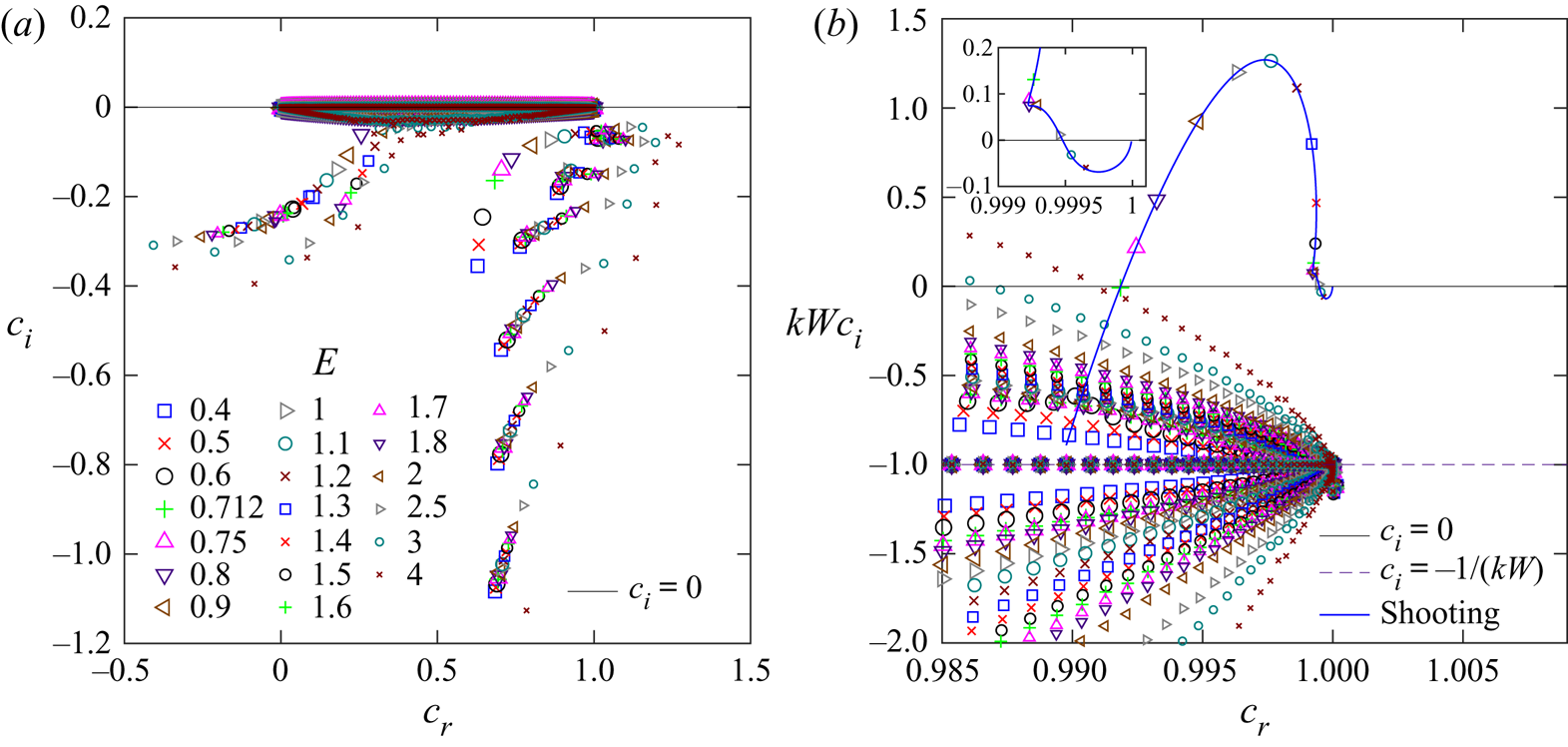
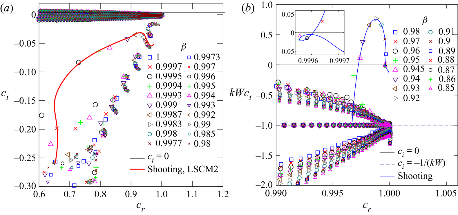
Figure 5 shows the spectra in the near-Newtonian limit of  $\beta = 0.96$ and for
 $E$ ranging over the interval
 $(0.4,4)$, overlaid in a single plot, in order to demonstrate the variation of not just the (eventually) unstable centre mode, but also of the other stable modes. For the higher
 $E$ considered in figure 5, the two CSs lie very close to
 $c_i = 0$ (and to each other for the chosen
 $\beta$), and the modes in the Newtonian P branch have therefore already disappeared into the CS, with new modes emerging from below. Thus, the trajectories of the modes shown in figure 5(a) are for the modes that start off below the CS. The enlarged version in figure 5(b) shows the spectra in terms of the scaled growth rate
 $kWc_i$, which fixes the vertical location of both the CS (for fixed
 $\beta$), and allows one to focus on the trajectory of the unstable centre mode with varying
 $E$. The continuous curve indicating the trajectory of the centre mode, as
 $E$ is varied, is obtained using the shooting method with much finer increments in
 $E$. This figure shows that the centre mode first emerges out of the CS, in the form of a bump in the continuous spectrum balloon, at
 $E \approx 0.6$, and becomes unstable as
 $E$ is increased to
 $0.712$. The centre mode remains unstable for
 $0.712 \leq E \leq 2.5$, but becomes stable for
 $E > 2.5$, with
 $|c_i|$ eventually scaling as
 $1/E$ for large
 $E$. Thus, figures 4 and 5(b) show that there are two qualitatively different trajectories of the unstable centre mode with increasing
 $E$. For the lower
 $\beta$
 $(=0.8)$, the centre mode appears as a smooth continuation of the least-stable Newtonian centre mode, whereas for
 $\beta = 0.96$, it emerges from the continuous spectrum, with no obvious connection to the Newtonian spectrum. This aspect is discussed in more detail in § 3.1.1.
(a) Eigenspectra for different values of  $E$ for
 $\beta =0.96$,
 $Re=500$ and
 $k=1$. (b) Enlarged version of the region in (a) near the unstable centre mode
 $c_r = 1$. The scaled growth rate
 $kWc_i$ fixes the vertical location of both the CS (for
 $\beta = 0.96$, CS1 and CS2 lie very close to each other). The continuous line for the trajectory of the unstable centre mode is obtained using the shooting method.

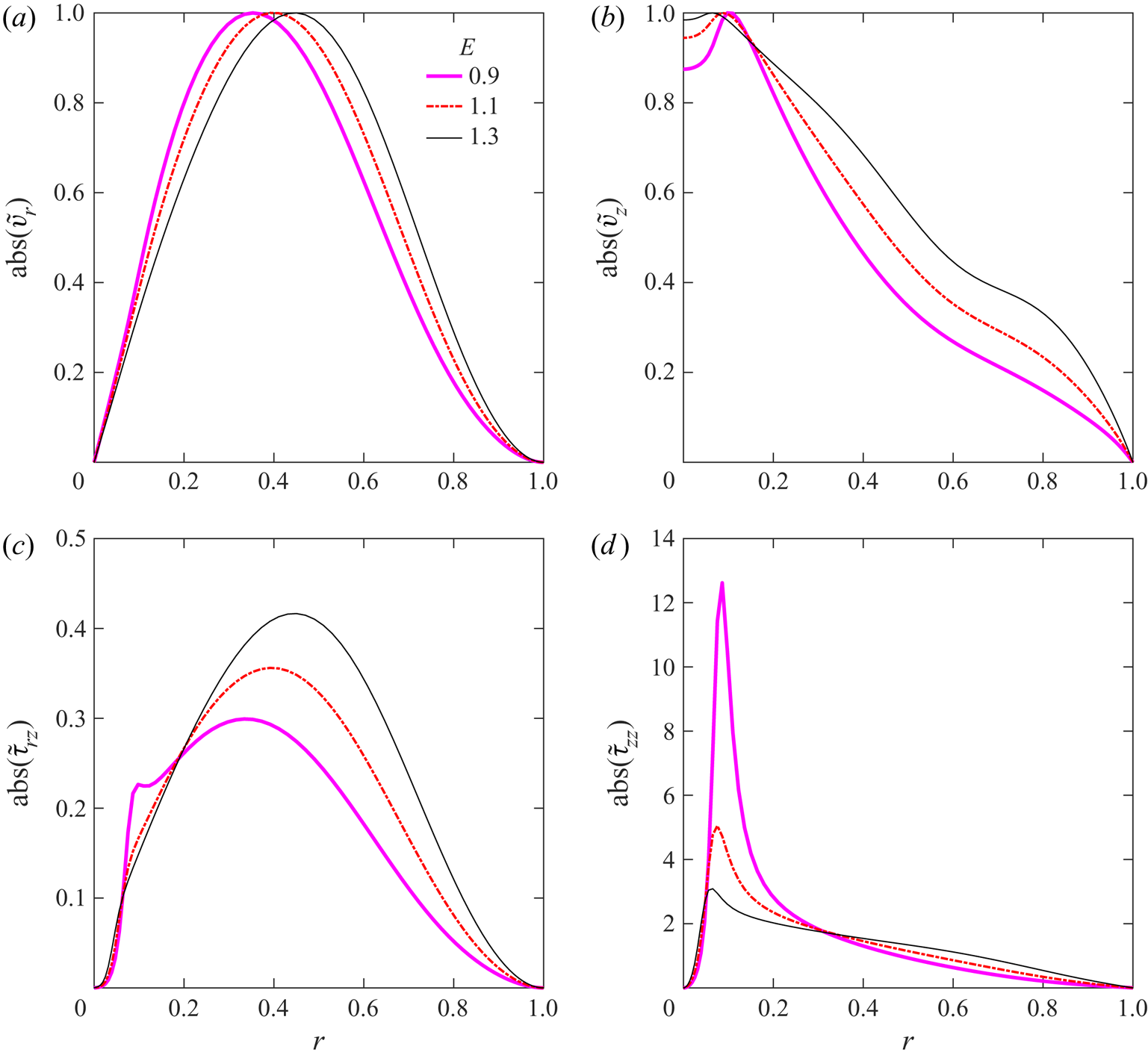
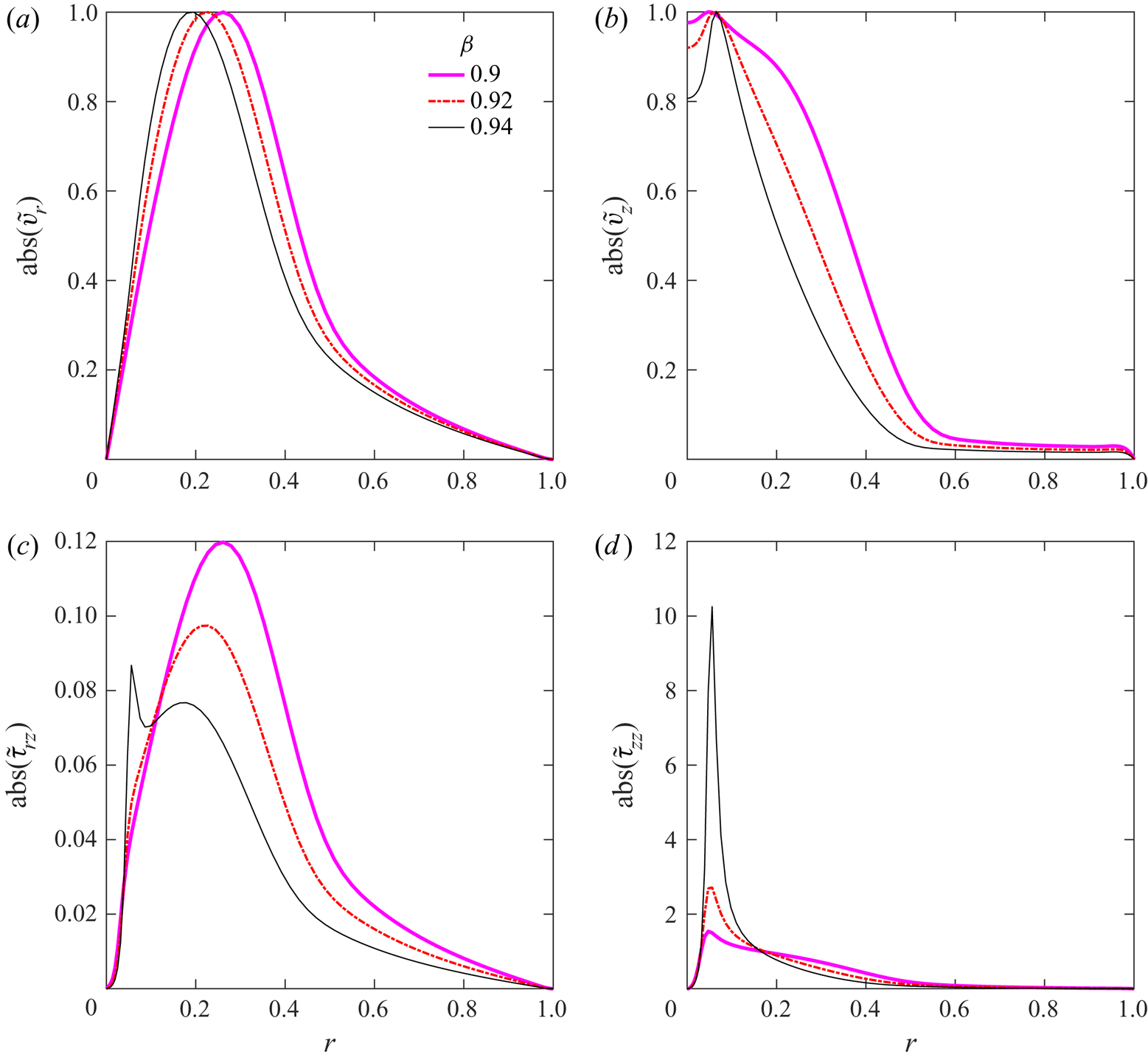
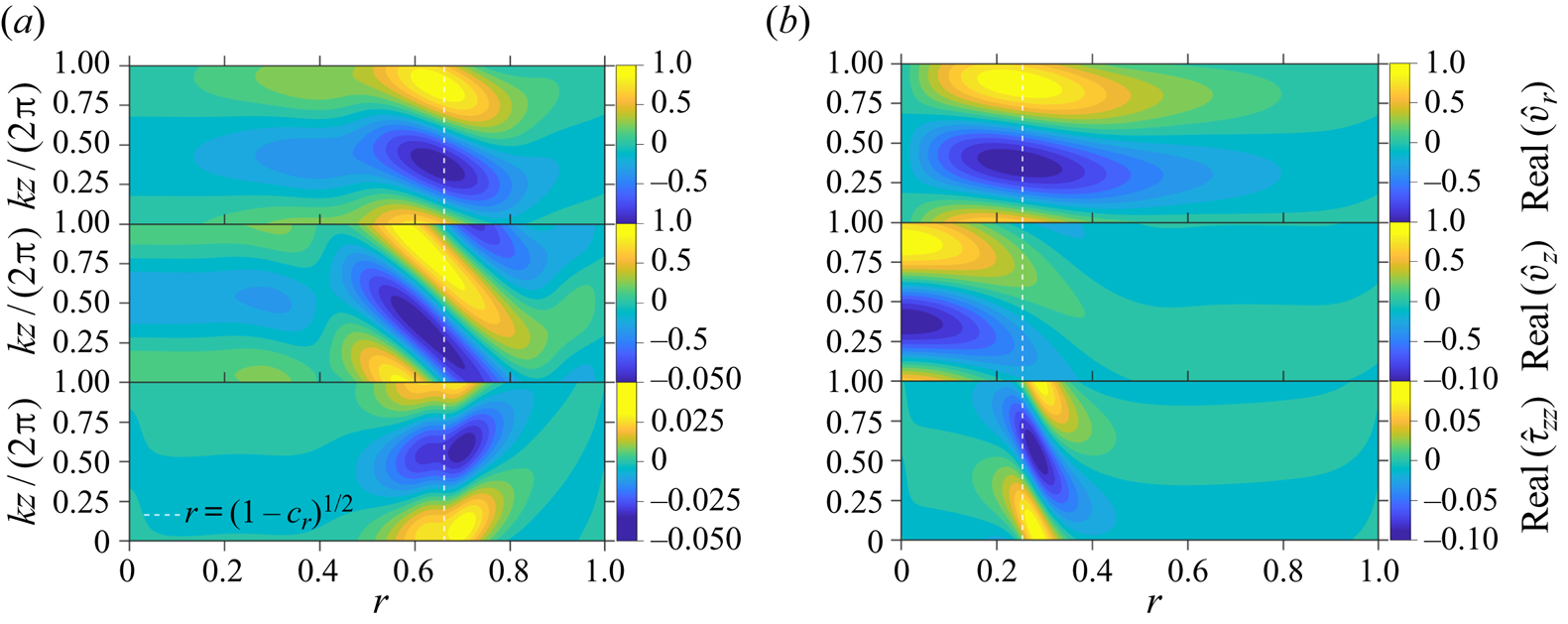
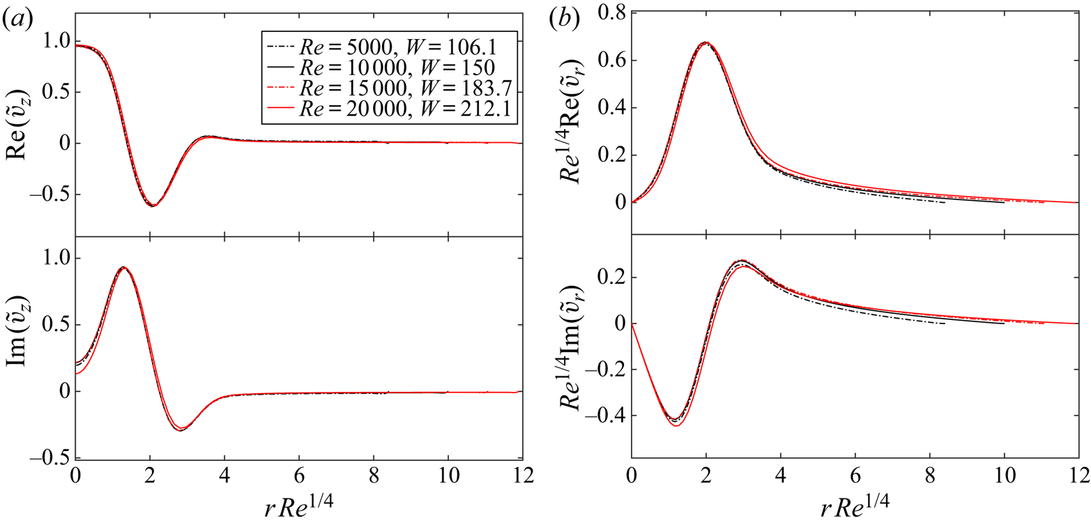
Figures 6(a)–6(d) show the velocity ( $v_r$ and
 $v_z)$ and stress (
 $T_{rz}$ and
 $T_{zz}$) eigenfunctions, for different
 $E$, corresponding to a few of the unstable centre modes shown in figure 5(b). The velocity and
 $T_{rz}$ eigenfunctions are largely insensitive to variations in
 $E$, but the
 $T_{zz}$ eigenfunction shows a distinct and sharp peak for the smaller
 $E$ (
 $= 0.9$) near the radial location where the phase speed of the disturbances equals the local base flow velocity. Although the amplitudes of the axial velocity eigenfunctions in figure 6 are larger near the central core region of the pipe, the disturbance fields are nevertheless spread across the entire pipe cross-section for the parameters considered. As shown in § 4.2, only for sufficiently large
 $Re$ (
 $>$1000) does the localization of the velocity eigenfunctions near the centre become prominent. It is worth emphasizing this feature here because recent studies (Shekar et al. Reference Shekar, McMullen, Wang, McKeon and Graham2019) have inaccurately characterized the centre mode instability, analysed in Garg et al. (Reference Garg, Chaudhary, Khalid, Shankar and Subramanian2018) and the present work, as always being localized in the vicinity of the centreline regardless of
 $Re$.
Velocity and polymer stress eigenfunctions corresponding to the unstable centre modes (in figure 5b) at different  $E$ for
 $\beta = 0.96$,
 $Re = 500$ and
 $k=1$: (a) radial velocity; (b) axial velocity; (c)
 $rz$ polymer stress; and (d)
 $zz$ polymer stress.

3.1.1. The origin of the centre mode at fixed $\beta$ and varying $E$


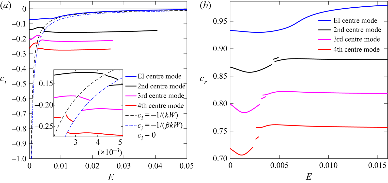
The origin of the centre mode is more clearly demonstrated in figure 7(a) through the variation of  $c_i$ with
 $E$ for the first four least-stable modes from the Newtonian P branch, obtained using the shooting method. For
 $\beta = 0.8$, consistent with the spectra in figure 4, the least-stable Newtonian centre mode always lies above the CS (figure 7a), smoothly continuing with increasing
 $E$, eventually becoming unstable for
 $E \approx 0.1$ (shown later in inset (A) of figure 9a). However, the other (more) stable Newtonian centre modes (labelled
 $2$,
 $3$ and
 $4$ in figure 4a) vanish into CS1 as
 $E$ is increased, and new modes appear out of CS1 with further increase in
 $E$, subsequently suffering a second jump across the CS2 line. The modes that emerge out of CS2 were those identified as
 $2'$,
 $3'$ and
 $4'$ in the spectra in figure 4. This feature is also evident in the variation of the phase speeds with
 $E$ in figure 7(b). An analogous phenomenon was reported by Chokshi & Kumaran (Reference Chokshi and Kumaran2009) for the least-stable wall mode in plane Couette flow of an Oldroyd-B fluid.
Effect of increasing  $E$ on the first four least-stable centre modes of Newtonian origin for
 $\beta = 0.8$,
 $Re = 600$ and
 $k = 3$. EI: elasto-inertial. (a) Growth rate versus
 $E$, with the inset presenting a magnified view of the jumps suffered by the individual modes as they cross CS1 (
 $c_i = -1/(kW)$) and CS2 (
 $c_i = -1/(\beta kW)$). (b) Phase speeds corresponding to the modes shown in (a).

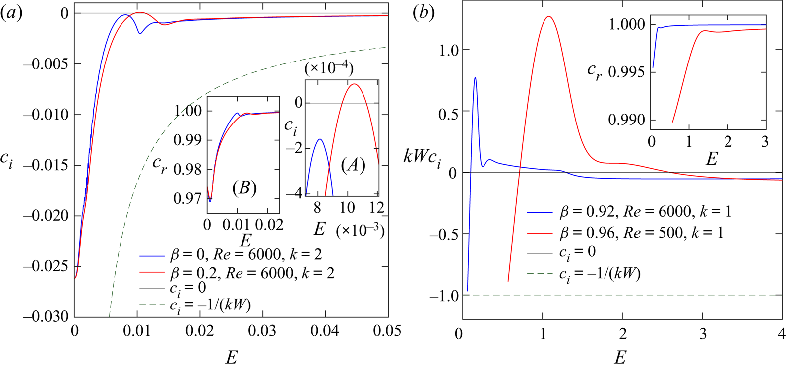
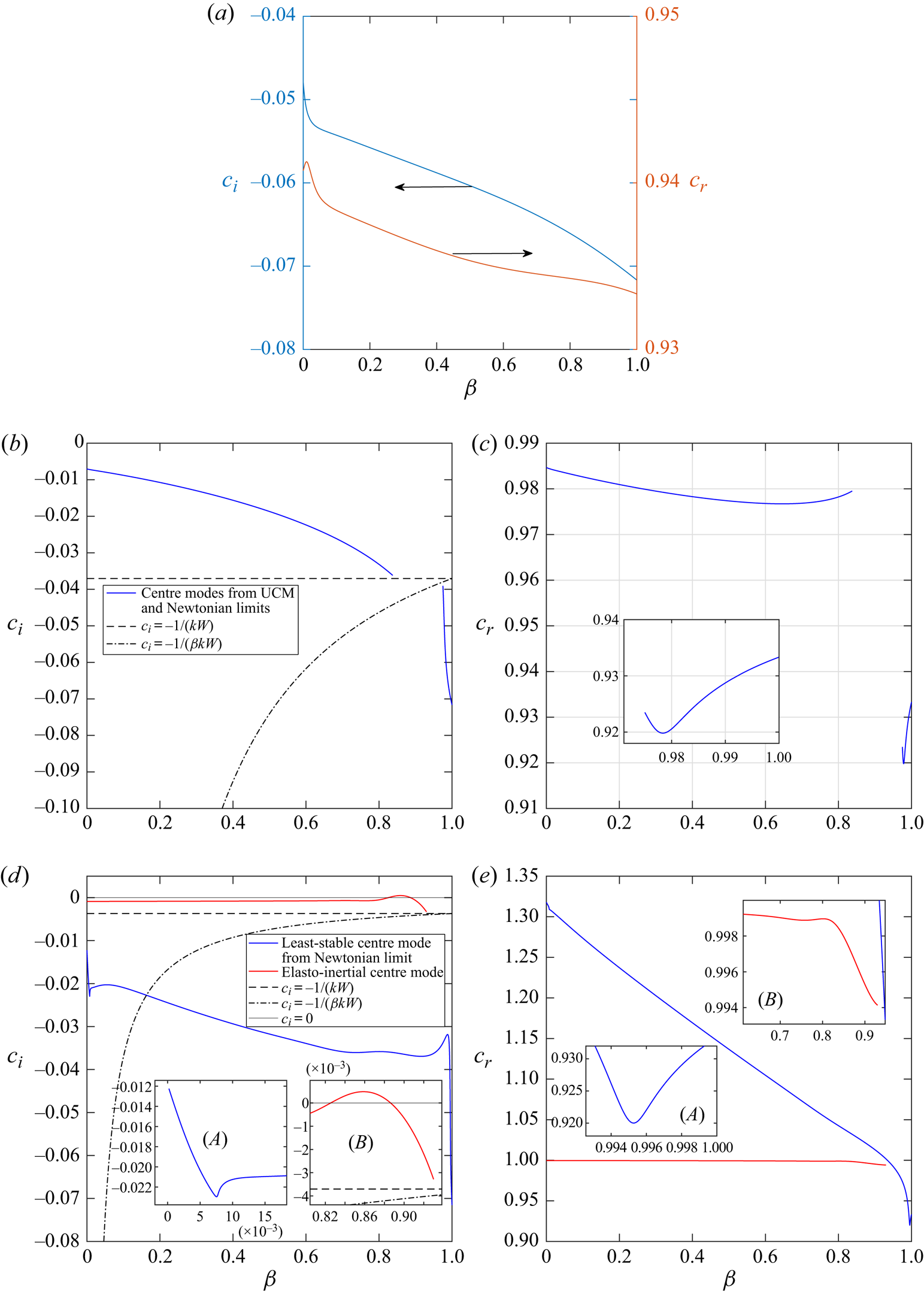
In figure 8(a), we examine the effect of increasing  $E$ in the UCM and near-UCM limits at fixed
 $Re$ and
 $k$ (note that, regardless of the value of
 $\beta$,
 $E = 0$ corresponds to the Newtonian limit). For
 $\beta = 0$, the decay rate of the least-stable Newtonian centre mode decreases with increasing
 $E$, even to the point of reducing to
 $\sim 2 \times 10^{-4}$ at
 $E \approx 8 \times 10^{-3}$ (about 1/100th of the decay rate in the Newtonian limit), but the mode remains stable. As elastic effects are responsible for the unstable centre mode, it might be expected that this instability should persist even in the absence of solvent contribution to the stress. The eigenspectra for pipe flow of a UCM fluid were computed for a vast range of parameters
 $0.5 < k < 3$,
 $100<Re<20\,000$ and
 $0<E<1$. Unlike the spectrum for plane channel flow of a UCM fluid (Sureshkumar & Beris Reference Sureshkumar and Beris1995; Chaudhary et al. Reference Chaudhary, Garg, Shankar and Subramanian2019), only stable modes were obtained for pipe flow of a UCM fluid subjected to axisymmetric disturbances. Thus, as originally stated in Garg et al. (Reference Garg, Chaudhary, Khalid, Shankar and Subramanian2018), the centre mode instability in viscoelastic pipe flow requires the combined effects of both the polymer elasticity and solvent viscous effects, in addition to fluid inertia.
Effect of increasing  $E$ on the least-stable Newtonian centre mode for UCM and Oldroyd-B fluids. (a) Plots of
 $c_i$ for the least-stable centre mode at
 $Re = 6000$ for
 $\beta = 0$ and
 $0.2$, with the inset (A) showing the enlarged region near the unstable range of the mode and inset (B) showing the corresponding phase speeds. (b) Scaled growth rate of elasto-inertial modes at
 $Re = 6000$,
 $\beta = 0.92$ and
 $Re = 500$,
 $\beta = 0.96$, and the inset showing the corresponding phase speeds.

For  $\beta = 0.2$ (see figure 8a), however, the least-stable Newtonian centre mode does become unstable for
 $0.01 < E < 0.011$. For both
 $\beta$, the centre mode trajectory is similar to that shown in figure 7, in that it remains above the CS over the range of
 $E$ examined. The corresponding phase speeds (inset (B) of figure 8a), for both
 $\beta = 0$ and
 $0.2$, show a weak non-monotonic behaviour with
 $E$, although
 $c_r \leq 1$ for all
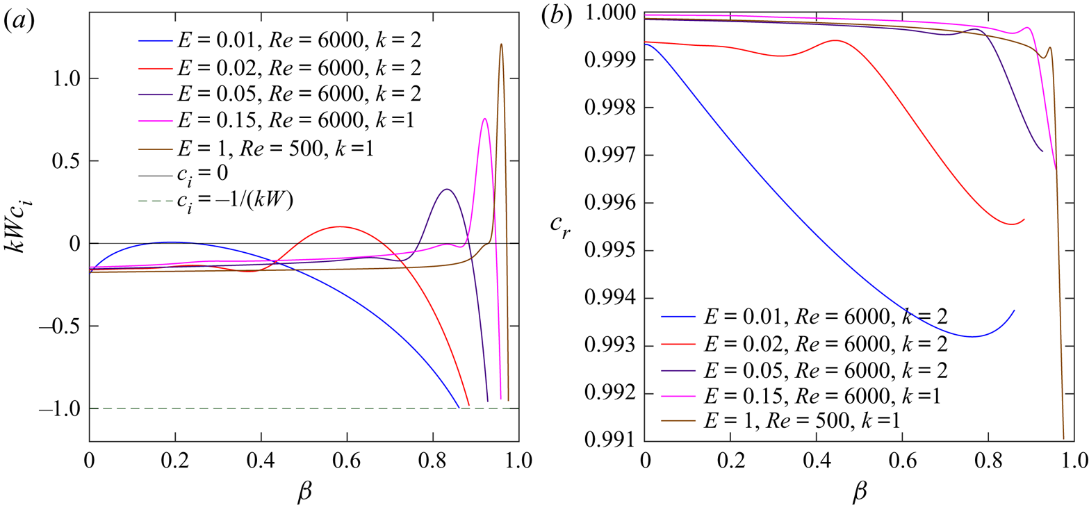
 $E$. The contrasting behaviour for
 $\beta$ close to unity (representing dilute solutions) is shown in figure 8(b). The main figure shows the variation of the scaled growth rate
 $kWc_i$ with
 $E$ for two different sets of (near-unity)
 $\beta$ and
 $Re$. The instability occurs at significantly larger values of
 $E \sim O(1)$, in contrast to figure 8(a), and the unstable range of
 $E$ is also larger. In contrast to the trend for
 $\beta = 0.2$, the continuation of the Newtonian centre modes for both
 $\beta = 0.92$ and
 $0.96$ collapses into the CS at smaller
 $E$ (not shown). It is the trajectories of the new discrete modes, that emerge from the CS at slightly larger
 $E$, and that become unstable for
 $E \sim O(1)$, that are shown in figure 8(b). The corresponding phase speeds for
 $\beta = 0.92$ and
 $0.96$ are shown in the inset of figure 8(b).
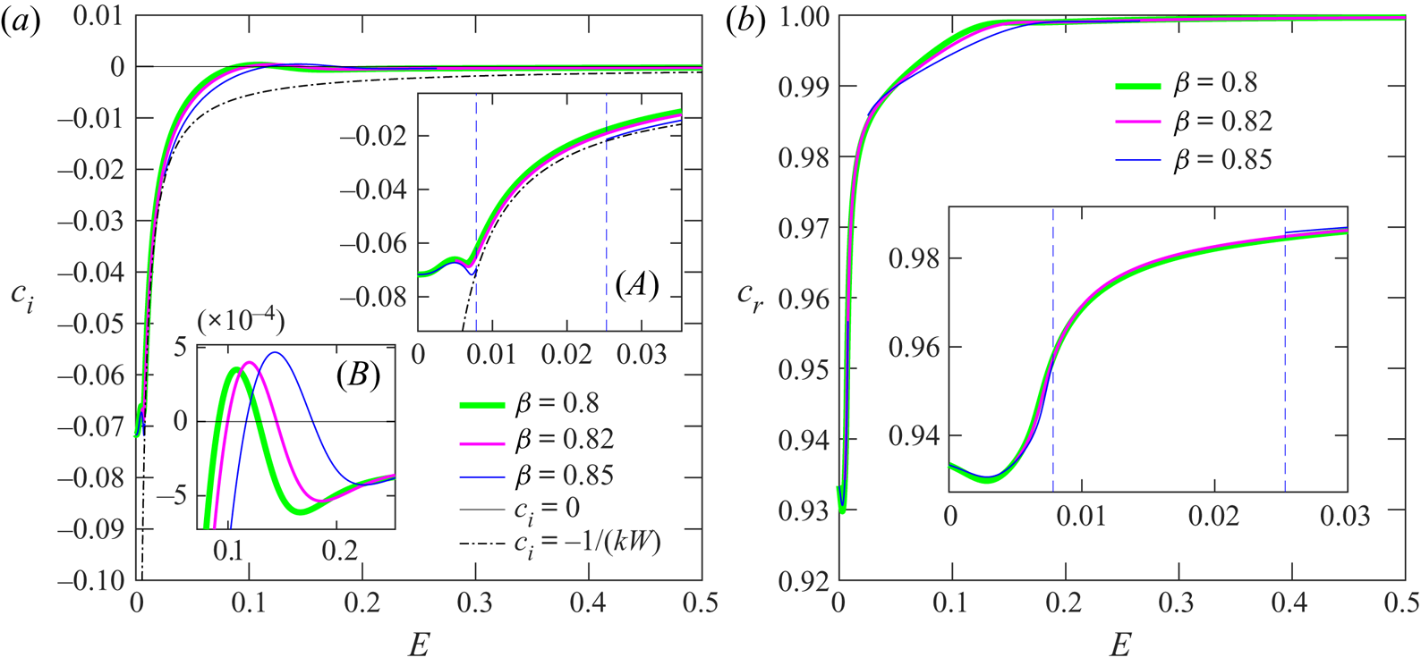
In figures 7 and 8, we show two different trajectories for the centre mode, as a function of  $E$, depending on
 $\beta$. In order to clarify the change in the nature of the centre mode trajectory, from a continuous variation of
 $c_i$ with increasing
 $E$ at smaller
 $\beta$, to a discontinuous variation for near-unity
 $\beta$, figure 9(a) shows the behaviour of the centre mode for
 $\beta = 0.8$,
 $0.82$ and
 $0.85$. The centre mode trajectory remains above CS1 until instability, for both
 $\beta = 0.8$ and
 $0.82$, whereas for
 $\beta = 0.85$, the centre mode disappears into the CS at
 $E \approx 0.009$ (inset (A) of figure 9a). Thus, in this case, there exists a range
 $0.009\lessapprox E \lessapprox 0.024$ where the centre mode does not exist. This range, which extends from the point of encounter of this mode with CS1 to the point of emergence of the new mode from CS1 at higher
 $E$, varies with increasing
 $\beta$. Evidently, the critical
 $\beta$, below which the centre mode is a smooth continuation of the least-stable Newtonian centre mode, lies somewhere between
 $0.82$ and
 $0.85$ (for
 $Re = 600$ and
 $k = 3$). Note that, despite the discontinuous transition in terms of the collapse into the CSs, the interval of instability in
 $E$ varies smoothly with increasing
 $\beta$ (the inset (B) in figure 9a). Figure 9(b) shows the corresponding phase speeds, and the enlarged region in the inset shows that the trend for
 $c_r$ versus
 $E$ curves is more or less same for
 $\beta = 0.8$,
 $0.82$ and
 $0.85$, except for
 $\beta =0.85$, where the absence of the mode in the interval
 $0.009\lessapprox E \lessapprox 0.024$ leads to a gap in the
 $c_r$ curve.
Effect of increasing  $E$ on the viscoelastic centre mode for fixed values of
 $\beta = 0.8$,
 $0.82$ and
 $0.85$,
 $Re = 600$ and
 $k = 3$. (a) Growth rates, with inset (A) showing the enlarged region over the range of
 $E$ for which the centre mode is discontinuous (marked by vertical dotted lines) owing to CS1 with
 $c_i=-1/(kW)$. The locations of CS2 (with
 $c_i = -1/(\beta k W)$) are not shown owing to the closely separated values of
 $\beta$ used in this figure. Inset (B) shows the region where the centre mode is unstable for all the three values of
 $\beta = 0.8$,
 $0.82$ and
 $0.85$. (b) Phase speeds corresponding to the modes shown in (a). Inset in (b) shows the enlarged region near
 $E \rightarrow 0$.

3.2. Spectra at fixed $E$ and different $\beta$


We next examine the viscoelastic eigenspectra as  $\beta$ is increased from zero, at fixed
 $E$. We begin with figure 10 which illustrates the effect of increasing
 $\beta$, starting from the UCM spectrum, at
 $E = 10^{-4}$. A moderate
 $Re$ (
 $=600$) is chosen in order to keep the spectral features relatively simple, requiring only a modest resolution (the number of collocation points
 $N$), and thereby allowing us to focus on the large-scale features. Figure 10 illustrates the singular feature of the bending down of the HFGL line for non-zero
 $\beta$. The bending down can be interpreted as a (very strong) stabilization of these modes owing to the solvent viscosity. For the larger
 $\beta$ (
 $0.5$ and
 $0.8$), the bending is ‘complete’, leading to the ring-like structure within the range of
 $c_i$ examined; this then clarifies the origin of the structure seen before in figure 3. Figure 11 shows spectra at a higher
 $Re$ (
 $=6000$), for different
 $\beta$, and with
 $E = 0.01$. The spectrum for
 $\beta = 0$ (figure 11a) now has a more intricate structure, necessitating an enlarged view of the phase speed interval
 $(0,1)$. The features of the high-
 $Re$ UCM channel-flow spectrum were first explained in Chaudhary et al. (Reference Chaudhary, Garg, Shankar and Subramanian2019), and include CS1 (which appears as a balloon owing to the finite resolution), the HFGL and additional discrete modes with
 $c_r \in [0,1]$ that lie on either side of the HFGL line, roughly along the contours of an ‘hourglass’. These features of the UCM pipe-flow spectrum, in figure 11(a), are analogous to the channel flow case described previously.
Eigenspectra for  $E = 10^{-4}$,
 $Re = 600$ and
 $k = 3$ demonstrating the bending down of the HFGL modes with increasing
 $\beta$, leading to the appearance of a ring-like structure for the higher
 $\beta$. The vertical location of CS1 is independent of
 $\beta$, whereas that of CS2 varies with
 $\beta$.

Unfiltered viscoelastic eigenspectra for  $E=0.01$,
 $Re=6000$,
 $k=2$ and different
 $\beta$: (a)
 $\beta = 0$, UCM; (b)
 $\beta = 1\times 10^{-4}$; (c)
 $\beta = 5\times 10^{-4}$; (d)
 $\beta = 5\times 10^{-3}$; (e)
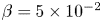 $\beta = 5\times 10^{-2}$; and (f)
 $\beta = 0.2$. The decay rate of the least-stable centre mode in the UCM limit decreases with increase in
 $\beta$ and the centre mode eventually becomes unstable at
 $\beta = 0.2$.

Figures 11(b)–11(d) show the spectra for  $\beta$ in the range
 $10^{-4}$–
 $5\times 10^{-3}$. Figure 11(b) shows that even the smallest
 $\beta$ has a profound effect on the HFGL modes. In contrast to the UCM spectrum at
 $Re = 600$ (figure 11a), where the bending of HFGL line became evident only for
 $c_r$ well outside the base-state interval, the bending down of the HFGL modes is evident at
 $Re = 6000$ even for
 $c_r \in (0,1)$; see figures 11(b) and 11(c). The bent HFGL line has all but disappeared as
 $\beta$ is increased to
 $10^{-3}$ (figure 11c), again demonstrating that the HFGL modes are rapidly damped by small amounts of solvent viscosity. Owing to this drastic stabilization even at rather small
 $\beta$, the HFGL modes in the original UCM spectrum become irrelevant to the parametric regimes (corresponding to relatively dilute solutions, with
 $\beta \sim 0.6$ and higher) explored later in this study. Further, the ‘density’ of stable modes present in the hourglass structure in the UCM limit also decreases rapidly as
 $\beta$ is increased from zero, with the hourglass structure virtually absent for
 $\beta = 0.05$. Most importantly, although almost all other modes in the hourglass structure of the UCM spectrum are rapidly stabilized with increasing
 $\beta$ (figures 11d–11f), the least-stable centre mode (with
 $c_r\approx 1$ and
 $c_i \rightarrow 0$) is rather unaffected by the small increase in
 $\beta$. In fact, as shown in figures 11(e) and 11(f), for the largest
 $\beta$ shown (
 $\beta = 0.2$), the centre mode becomes unstable. Thus, as originally stated in figure 8(a), it appears that all three effects, namely, elasticity, solvent viscous stresses and fluid inertia are important ingredients for the instability of the centre mode in viscoelastic pipe flow.
In figure 12, we show the eigenspectra (overlaid) as  $\beta$ is reduced from unity, again at fixed
 $E$,
 $Re$ and
 $k$; note that the
 $\beta$ shown are all higher than the threshold value for collapse into the CS (the analogue of that identified in figure 9a, but for
 $Re = 6000$). Figure 12(a) is for
 $\beta$ close enough to unity that the centre mode has not emerged out of the CS yet (the other stable modes, with
 $c_r \rightarrow 0$, are not shown). Thus, the trends in this figure pertain to all other (least-stable) modes on the P branch. Figure 12(a) shows no discernible trend in the behaviour of the P branch modes with changing
 $\beta$. For instance, as
 $\beta$ is decreased, the least-stable Newtonian mode moves in the clockwise sense in
 $(c_r,c_i)$-plane. In contrast, the mode LSCM2 smoothly continues from a Newtonian mode at the junction of the ‘APS’ structure present at
 $\beta = 0$. The remaining modes are, however, smooth continuations of the modes of the Newtonian P branch, but these move in the counter-clockwise sense with decreasing
 $\beta$. Eigenspectra for smaller
 $\beta$ in the interval
 $0.85\leq \beta \leq 0.98$ are shown in figure 12(b), the focus being on the centre mode. The centre mode first emerges at
 $\beta = 0.96$, and becomes unstable for
 $\beta \in [0.88,0.945]$. The smooth (blue) curve, passing through the spectral centre mode eigenvalues, shows the trajectory of the centre mode with decreasing
 $\beta$, obtained using the shooting method.
Thus, at a fixed
 $E$, the unstable centre mode always emerges out of the CS as
 $\beta$ is decreased from unity.
Viscoelastic pipe-flow eigenspectra for  $E=0.15$,
 $Re=6000$,
 $k=1$ and for varying
 $\beta$: (a)
 $(1-\beta )=0$ to
 $0.02$; and (b)
 $(1-\beta )=0.02$ to
 $0.15$. Panel (a) shows the region in the vicinity of the
 ${\rm P}$ branch. Panel (b) focuses on the trajectory of the centre mode that becomes unstable for
 $\beta \in (0.88,0.945)$.

The velocity and stress eigenfunctions corresponding to some of the unstable centre modes in figure 12(b) are shown in figure 13. For the higher  $Re$ (
 $= 6000$), the axial velocity eigenfunctions are more localized near the centre (as
 $\beta$ approaches unity), compared with those for
 $Re = 600$ shown in figure 6(b). The axial stress
 $T_{zz}$ (figure 13d) shows a sharp peak as
 $\beta$ approaches unity at fixed
 $E$, similar to the feature that was seen earlier (figure 6d), albeit with decreasing
 $E$ at a fixed
 $\beta$ for
 $Re = 600$. For the values of
 $\beta$ examined here, both the axial and radial eigenfunctions exhibit a rather smooth variation with
 $r$, unlike the rapid, oscillatory variation (not shown) characteristic of wall modes (
 $c_r \rightarrow 0$) for
 $\beta \rightarrow 0$. The latter are analogous to wall modes in viscoelastic channel flow whose structures was examined in detail by Chaudhary et al. (Reference Chaudhary, Garg, Shankar and Subramanian2019) (see figure 20 therein); the overall similarity of the pipe and channel flow UCM spectra was discussed previously.
Velocity and polymer stress eigenfunctions corresponding to the unstable centre modes (in figure 12b) at different  $\beta$ for
 $E = 0.15$,
 $Re = 6000$ and
 $k=1$: (a) radial velocity; (b) axial velocity; (c)
 $T_{rz}$ stress; and (d)
 $T_{zz}$ stress.

3.2.1. The origin of the centre mode at fixed $E$ and varying $\beta$


While the discussion pertaining to figure 12(b) showed that centre mode emerges out of the CS as  $\beta$ is decreased from unity, in figure 14(a), we address the question of what happens as
 $\beta$ decreases to zero (the UCM limit). This figure shows the variation of the scaled growth rate,
 $kWc_i$, of the centre mode with varying
 $\beta$ at fixed
 $Re$,
 $E$ and
 $k$. As
 $\beta$ decreases from unity, the centre mode emerges out of CS1 (when
 $kWc_i = -1$) at a critical
 $\beta$, and becomes unstable as
 $\beta$ decreases further. The critical
 $\beta$ corresponding to the emergence of the centre mode is closer to unity for higher
 $E$. The range of unstable
 $\beta$ also approaches unity for larger
 $E$, while also narrowing down in extent, with a concomitant increase in the growth rate. A similar narrowing down occurs when
 $E$ approaches the lower threshold for the instability, for the chosen
 $\beta$ (the blue curve in figure 14a). Figure 14(b) shows that the corresponding
 $c_r$ remains close to (and less than) unity for the entire range of
 $\beta$.
(a) Scaled growth rate and (b) phase speed, for the centre mode, with varying  $\beta$, for different fixed sets of parameters
 $(E,Re, k) = (0.01, 6000, 2), (0.02, 6000, 2), (0.05, 6000, 2), (0.15, 6000, 1)$ and
 $(1, 500, 1)$.

In figure 15, we show the three possible behaviours, within the parameter regimes explored, for the trajectory of the least-stable centre mode as  $\beta$ is varied from the UCM to the Newtonian limit. For the smallest elasticities (e.g.
 $E = 0.005$ in figure 15a), when the two CS are highly stable, and well outside the range of
 $c_i$ shown, the centre mode, while remaining stable, smoothly continues all the way from the UCM limit (
 $\beta = 0$) to the Newtonian (
 $\beta = 1$) limit without suffering any discontinuities or abrupt endings. For moderate elasticities (e.g.
 $E = 0.015$ shown in figure 15b), the
 $c_i$ versus
 $\beta$ curve for the least-stable centre mode starts from the Newtonian end (
 $\beta = 1$), but abruptly ends as it encounters CS2 from below. On the other hand, the least-stable centre mode in the UCM limit continues to finite
 $\beta$, abruptly ending at the location of its encounter with CS1 from above. Corresponding phase speeds for
 $E = 0.015$ are shown in figure 15(c), with the inset showing an enlarged view near
 $\beta =1$, where the variation of the phase speed
 $c_r$ with
 $\beta$ is quite sharp. For the chosen parameters, the centre mode still remains stable for all
 $\beta$. Finally, for higher elasticity (e.g.
 $E = 0.15$), the
 $c_i$ versus
 $\beta$ curve for the least-stable mode from the Newtonian end continues all the way up to the UCM limit without suffering discontinuities as shown in figure 15(d), ending up as a centre mode in the UCM spectrum. Inset (A) shows a magnified view of the sharp variation of the
 $c_i$ curve near
 $\beta =0$. The least-stable centre mode in the UCM limit behaves similar to the previous case of
 $E=0.015$, with an abrupt ending as it collapses onto CS1 from above, the only difference now being that the mode is unstable for a small range of
 $\beta$ (owing to the higher
 $E$); inset (B) provides the enlarged view of the unstable range of
 $\beta$. The corresponding phase speeds for
 $E=0.15$ are shown in figure 15(e) with inset (A) showing the enlarged view of the non-monotonic behaviour near the Newtonian limit. Note that the Newtonian centre mode does not suffer a jump despite crossing the CS2 curve (
 $c_i = -1/(\beta kW)$) in figure 15(d); this is only an apparent crossing since, as shown in figure 15(e), its phase speed exceeds unity, and it therefore ‘goes around’ CS2 with decreasing
 $\beta$. In contrast, the discontinuities in the centre mode trajectory, in figure 15(b), occur because
 $0 < c_r < 1$.
The three possible centre mode trajectories with variation in  $\beta$ for
 $Re=600$,
 $k=3$ at various fixed values of the elasticity number:
 $E = 0.005$ in (a),
 $E = 0.015$ in (b,c), and
 $E = 0.15$ in (d,e). Insets
 $(A)$ in (d) and (e) show the enlarged regions near
 $\beta =0$ and
 $\beta = 1$, respectively. Inset
 $(B)$ in panels (d) show the enlarged views of the unstable range of
 $\beta$. (a) Growth rate and phase speed; (b) growth rate; (c) phase speed; (d) growth rate; and (e) phase speed.

3.3. Centre versus wall modes in viscoelastic pipe and channel flows
In the results presented so far, we have characterized the behaviour of the elasto-inertial centre mode as a function of  $E$ and
 $\beta$. Although this mode may either be directly related to a Newtonian centre mode (for
 $\beta$ below a threshold), or be disconnected from the Newtonian spectrum (for
 $\beta$ above), the interpretation is nevertheless that the EIT observed in recent experiments (Samanta et al. Reference Samanta, Dubief, Holzner, Schäfer, Morozov, Wagner and Hof2013; Chandra et al. Reference Chandra, Shankar and Das2018; Choueiri et al. Reference Choueiri, Lopez and Hof2018) is the outcome of a linear instability associated with this centre mode. In sharp contrast to this picture, in a recent effort, Shekar et al. (Reference Shekar, McMullen, Wang, McKeon and Graham2019) have argued based on DNS and a singular-value decomposition analysis that EIT in channel flow might instead be closely related to the elastically modified TS mode. As is well known, the TS mode is the least-stable wall mode in the Newtonian limit, and this remains true for the range of elasticities considered by the authors. Thus, the premise of Shekar et al. (Reference Shekar, McMullen, Wang, McKeon and Graham2019) continues to be along the lines of a subcritical bifurcation to EIT, similar in spirit to the earlier efforts of Meulenbroek et al. (Reference Meulenbroek, Storm, Bertola, Wagner, Bonn and van Saarloos2003) and Morozov & van Saarloos (Reference Morozov and van Saarloos2005, Reference Morozov and van Saarloos2007) in the inertialess limit, and to the work of Stone et al. (Reference Stone, Waleffe and Graham2002), Stone & Graham (Reference Stone and Graham2003), Stone et al. (Reference Stone, Roy, Larson, Waleffe and Graham2004) and Li & Graham (Reference Li and Graham2007) based on an elastic modification of 3D ECS structures. The main difference is that the bifurcation ascribed by Shekar et al. (Reference Shekar, McMullen, Wang, McKeon and Graham2019) is supposedly to a finite amplitude 2D mode, with EIT-like dynamics. The authors reported results for
 $Re = 1500$ (where the Newtonian flow is turbulent),
 $\beta = 0.97$, and for
 $0 < W < 50$. It is worth noting that, for these parameters, the elastically modified ECSs originally examined by Graham and co-workers (Li & Graham Reference Li and Graham2007) also exist, although Shekar et al. (Reference Shekar, McMullen, Wang, McKeon and Graham2019) restrict themselves to two-dimensional initial conditions.
While the present study is restricted to linear (modal) stability of pipe flow of an Oldroyd-B fluid, it is nevertheless instructive to compare the viscoelastic pipe and channel flow spectra in order to assess the relative importance of centre and wall modes in these geometries. Such an assessment would help set the template (in terms of the relevant linear modes, both discrete and continuous) for a nonlinear bifurcation analysis. We show representative eigenspectra for pipe flow (in figure 16) for a range of  $E$ that subsumes the range (
 $0 < E < 0.013$) considered by Shekar et al. (Reference Shekar, McMullen, Wang, McKeon and Graham2019), for
 $\beta = 0.97$,
 $Re = 1500$ and
 $k=0.4{\rm \pi}$. In each panel, the corresponding Newtonian spectrum is also shown for comparison (as open blue circles). For
 $0.0005 <E < 0.05$, with increasing
 $E$, discrete modes collapse into the CS, and new ones emerge from below, similar to what was shown in figure 3. The centre mode emerges from CS1 at
 $E = 0.46$, (see inset of figure 16d), becoming unstable at
 $E \approx 0.5$ (figure 16e). Importantly, for the parameters considered in figure 16, the centre mode always remains the least-stable or least-unstable mode. This feature remains true even for other regimes investigated in this study (
 $Re \in 100$–
 $2000$). This is unlike Newtonian channel flow, where there is a range of parameters where the wall mode (i.e. the TS mode) is the least stable (or unstable), and this remains true for small but finite
 $E$.
Viscoelastic pipe-flow eigenspectra at  $\beta = 0.97$ for different
 $E$: (a)
 $0.0005$, (b)
 $0.005$, (c)
 $0.05$, (d)
 $0.46$ and (e)
 $0.5$, compared with the Newtonian eigenspectrum (
 $E =0$), for
 $Re = 1500$ and
 $k=0.4{\rm \pi}$.

An important feature of Newtonian pipe flow is the absence of a critical-layer singularity (Drazin & Reid Reference Drazin and Reid1981; Schmid & Henningson Reference Schmid and Henningson2001) for axisymmetric disturbances, as a result of which there is no axisymmetric analogue of the two-dimensional TS instability. This difference between pipe and channel flows appears to persist even in the presence of elasticity. In figure 17, we show, via contour plots, the spatial structure of the least-stable centre and wall modes marked in figure 16(b). Further, and in sharp contrast to viscoelastic channel flow, where the elastically modified TS mode was shown to have the  $T_{xx}$ (the stream-wise component of the normal stress) eigenfunction strongly localized in the critical layer (see figure 2 of Shekar et al. Reference Shekar, McMullen, Wang, McKeon and Graham2019), neither the least-stable centre nor the wall mode in pipe flow exhibits a comparably strong localization of
 $T_{zz}$; in fact, the extent of localization is more stronger for the centre mode. For these reasons, the connection between the (stable) TS wall mode to the elasto-inertial structures suggested by Shekar et al. (Reference Shekar, McMullen, Wang, McKeon and Graham2019) (in the context of viscoelastic channel flow) is not applicable for viscoelastic pipe flow. This aspect will be discussed in more detail in a future communication (Khalid et al. Reference Khalid, Chaudhary, Garg, Shankar and Subramanian2021), where we show that, even for viscoelastic channel flows, the parameter regime relevant to the proposed TS-mode-based subcritical mechanism of Shekar et al. (Reference Shekar, McMullen, Wang, McKeon and Graham2019) is somewhat restricted. It is worth emphasizing that all of the experiments on viscoelastic transition (with the exception of Srinivas & Kumaran Reference Srinivas and Kumaran2017) pertain to the pipe geometry. Further, and importantly, recent simulations in both the channel (Samanta et al. Reference Samanta, Dubief, Holzner, Schäfer, Morozov, Wagner and Hof2013; Sid et al. Reference Sid, Terrapon and Dubief2018) and pipe (Lopez et al. Reference Lopez, Choueiri and Hof2019) geometries have found analogous (span-wise oriented) coherent structures, suggesting a common underlying mechanism for elasto-inertial transition.
Contours of the radial ( $\hat {v}_r$), axial (
 $\hat {v}_x$) velocities and axial normal stress (
 $\hat {\tau }_{zz}$) in the
 $r$–
 $z$ plane for the least-stable wall and centre modes (marked in figure 16b) in pipe flow for
 $E = 0.005, \beta = 0.97, Re =1500$ and
 $k = 0.4{\rm \pi}$: (a) least-stable wall mode
 $c = 0.561844626 - 0.233038878\mathrm {i}$ from the A branch of the eigenspectrum; and (b) for the least-stable centre mode
 $c = 0.935239154-0.064928230\mathrm {i}$ from the P branch of the eigenspectrum. The location of the critical layer is shown using white dashed lines.

4. Neutral stability curves
Figures 18(a) and 18(b) show the neutral stability curves in the  $Re$–
 $k$ plane for fixed
 $\beta$ and
 $E$. The curves are in the form of loops, with the region inside the loop being unstable. Although
 $Re \sim 1/k$ for
 $k \ll 1$ in the lower and upper branches of the loop for the smaller
 $\beta$ (
 $=0.6$), the upper branch behaves in a different manner for
 $\beta = 0.9$. In figure 18(b), the upper branch has a non-monotonic behaviour as
 $E$ is increased, with a secondary minimum emerging at a higher
 $Re$. This feature of multiple minima is reminiscent of a similar phenomenon observed, albeit for wall modes, in the UCM limit for plane channel flow (see figure 15 of Chaudhary et al. Reference Chaudhary, Garg, Shankar and Subramanian2019). The two minima move apart with increasing
 $E$, and for
 $E \geq 0.8$, the junction of the two distinct lobes in a given neutral curve moves out of the range of
 $Re$ examined. Thus, the neutral curves for
 $E \geq 0.8$ appear as a pair of disconnected envelopes. Both branches of the lower envelope exhibit the aforementioned
 $1/k$ scaling for small
 $k$. In contrast, only the lower branch of the upper envelope exhibits this scaling, with the upper branch being almost vertical (figure 18b). The phase speeds corresponding to the neutral curves shown in figures 18(a) and 18(b) are shown in figures 19(a) and 19(b) respectively. Overall, the phase speeds always remain close to, but less than, unity (the maximum base-flow velocity). For the higher
 $\beta$,
 $c_r$ varies in a narrower range close to unity, approaching it more closely at the higher
 $E$ (figure 19b), but never exceeding unity. Thus, the centre mode character of the instability is preserved all along the neutral curves. Similar to the two-lobed structure of the neutral curves in the
 $Re$–
 $k$ plane for
 $\beta = 0.9$ (figure 18b), a corresponding two-lobed structure is seen in the
 $c_r$–
 $k$ plane as well for
 $E \approx 0.15$ onwards.
Neutral stability curves in the  $Re$–
 $k$ plane for varying
 $E$ at: (a)
 $\beta =0.65$ and (b)
 $\beta =0.9$.

The variation of the phase speed, as a function of  $k$, corresponding to the neutral curves for different
 $E$ in figure 18 at two different values of
 $\beta$: (a)
 $\beta =0.65$ and (b).

For a given  $E$ and
 $\beta$, the minimum of the neutral curve (the global one when there are multiple lobes) is the critical Reynolds number (
 $Re_c$), the lowest Reynolds number at which the flow is unstable. We mainly focus on the lower curve only, because the critical Reynolds number
 $Re_c$ lies on it. To begin with, an increase in
 $E$ shifts the neutral curves to lower
 $Re$ and
 $k$, but beyond a certain critical
 $E$, the neutral curves again shift towards higher
 $Re$. Interestingly, the minima of the neutral curves are
 $O(100)$ for sufficiently high
 $E$ (as first reported in our letter; Garg et al. Reference Garg, Chaudhary, Khalid, Shankar and Subramanian2018), as opposed to a typical
 $Re$ of
 $O(2000)$ for the Newtonian transition. The
 $Re \propto k^{-1}$ scaling followed by the lower branches of the neutral curves in figure 18 suggests a regular perturbation analysis in the
 $k \ll 1$ limit wherein (2.8)–(2.14) can be simplified by systematically neglecting terms of
 $O(k)$ or higher. From the neutral curves at fixed
 $E$, one obtains
 $Re = k^{-1}\tilde {Re}$,
 $W = k^{-1}\tilde {W}$ for the
 $k$-scalings of the dimensionless parameters. The radial velocity may be expanded as
 \begin{equation} \tilde{v}_r \equiv \tilde{v}_r^{(0)} + k \tilde{v}_r^{(1)} + k^2 \tilde{v}_r^{(2)} + \cdots, \end{equation}
which, when substituted in the continuity,  $z$-momentum,
 $rr$-,
 $rz$- and
 $zz$-stress equations, i.e. (2.8), (2.10)–(2.12) and (2.14), yields the following scalings at leading order:
 \begin{equation} \left. \begin{gathered} \displaystyle\tilde{v}_r \sim\tilde{v}_r^{(0)},\quad \tilde{v}_z \sim k^{{-}1}\tilde{v}_z^{(0)},\quad \tilde{p} \sim k^{{-}1}\tilde{p}^{(0)},\\ \displaystyle\tilde{\tau}_{rr} \sim k\tilde{\tau}_{rr}^{(0)},\quad \tilde{\tau}_{rz} \sim \tilde{\tau}_{rz}^{(0)},\quad \tilde{\tau}_{zz} \sim k^{{-}1} \tilde{\tau}_{zz}^{(0)}, \end{gathered}\right\}\end{equation}
These scalings are used in (2.8)–(2.10) to obtain the following simplified set of equations, to leading order in  $k$:
 \begin{gather} \left(\mathrm{D}+\frac{1}{r}\right) \tilde{v}_r^{(0)} + \mathrm{i} \tilde{v}_z^{(0)} = 0, \end{gather}
 \begin{gather}\mathrm{D}\tilde{p}^{(0)} = 0, \end{gather}
 \begin{gather}-U'\tilde{v}_r^{(0)} + \left\{\frac{\beta}{\tilde{Re}} (\mathrm{D}^2 + \frac{\mathrm{D}}{r}) - \mathrm{i}(U-c)\right\}\tilde{v}_z^{(0)} - \mathrm{i}\tilde{p}^{(0)} + \left(\mathrm{D}+\frac{1}{r}\right) \tilde{\tau}_{rz}^{(0)} + \mathrm{i}\tilde{\tau}_{zz}^{(0)}=0. \end{gather}
The boundary conditions become
 \begin{equation} \left.\begin{aligned} \displaystyle\tilde{v}_r^{(0)}&=0=\tilde{v}_z^{(0)} \quad \mbox{at}\ r=1,\\ \displaystyle \tilde{v}_r^{(0)}&=0, \quad \tilde{v}_z^{(0)} = \text{finite,}\quad \tilde{p}^{(0)} = \text{ finite} \quad \mbox{at}\ r=0. \end{aligned}\right\} \end{equation}
The simplified system comprising (4.3)–(4.5) was solved using a spectral method and the eigenspectrum obtained is compared with that for the full problem at  $k = 0.3$ for the same parameters (figure 20); the inset shows an enlarged view of the unstable centre mode. Both eigenspectra have a similar structure and, in particular, the centre mode obtained from the low-
 $k$ analysis has the same phase speed and growth rate as that in the original problem.
Comparison of the (unfiltered) asymptotic small- $k$ eigenspectrum with that obtained from the full problem for
 $\beta =0.9$,
 $E=0.15$,
 $k=0.3$ and
 $Re=8000$. The inset shows an enlarged view of the region near the unstable mode.

4.1. Collapse of neutral curves
The qualitatively similar character of the neutral curves at different  $E$ in figure 18 is strongly suggestive of a collapse upon suitable rescaling of both
 $Re$ and
 $k$ with the elasticity number
 $E$. Figure 21 shows that such a collapse is indeed possible for sufficiently small
 $E$, when
 $Re$ is rescaled as
 $Re E^{3/2}$ and
 $k$ as
 $k E^{1/2}$. These scalings are found to be valid for fixed
 $\beta$, although the nature of the collapsed curve does depend on
 $\beta$ (as evident from figures 21a and 21c). Similarly, as shown in figures 21(b) and 21(d), the curves for the rescaled phase speed
 $(1-c_r)/E$, plotted as a function of
 $kE^{1/2}$, again exhibit a collapse, implying that
 $(1-c_r)$ is
 $O(E)$ for
 $E \ll 1$.
Collapse of neutral curves for different  $E$ in the
 $Re$–
 $k$ plane (a,c) and collapse of the corresponding phase speeds (b,d) for two different
 $\beta$: (a) rescaled neutral curves for
 $\beta = 0.65$; (b)
 $(1-c_r)$ collapse for
 $\beta =0.65$; (c) rescaled neutral curves for
 $\beta = 0.9$ and (d)
 $(1-c_r)$ collapse for
 $\beta =0.9$.

While the collapse obtained above is for a fixed  $\beta$ and for
 $E \ll 1$, a further collapse is obtained in the dual limit
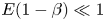 $E (1-\beta ) \ll 1$,
 $(1-\beta ) \ll 1$, when the neutral curves are plotted in terms of
 $Re[(1-\beta )E]^{3/2}$ and
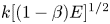 $k [(1-\beta )E]^{1/2}$ as shown in figure 22, implying that the threshold
 $Re$ and
 $k$ scale as
 $Re \propto [(1-\beta )E]^{-3/2}$ and
 $k \propto [(1-\beta )E]^{-1/2}$, respectively, in this limit. The rescaled neutral curves in figure 22 begin to collapse onto a single one only for
 $\beta > 0.9$, the collapse being perfect for the lower branch, but less so for the upper ones. Thus, the role of the solvent viscosity appears to be ‘universal’ only as far as the lower branch is concerned. Importantly, however, since the critical
 $Re$ occurs on the lower branches of the neutral curves, the transition to the elasto-inertial turbulent state is governed by the combination
 $E(1-\beta )$ for
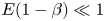 $E (1-\beta ) \ll 1$,
 $(1-\beta ) \ll 1$. It is worth noting that the nearly vertical nature of the upper branch implies that the instability appears to exist in the limit of
 $Re \rightarrow \infty$, with
 $E$ fixed. An axisymmetric version of the ‘elastic Rayleigh’ equation (the elastic analogue of the classical Rayleigh equation; see Rallison & Hinch Reference Rallison and Hinch1995; Subramanian et al. Reference Subramanian, Reddy and Roy2020), which also has
 $E(1-\beta )$ as the governing parameter, is known to govern the linearized dynamics of perturbations in this limit, and involves a balance of inertial and elastic forces in the fluid. There is, however, no instability associated with the elastic Rayleigh equation for plane- (Kaffel & Renardy Reference Kaffel and Renardy2010) and pipe-Poiseuille (Chaudhary, Shankar & Subramanian Reference Chaudhary, Shankar and Subramanian2020) flows, and the lack of collapse of the (near-vertical) upper branches, and the implied instability for
 $Re \rightarrow \infty$, in figure 22, betrays therefore the singular nature of the inviscid elastic limit, with viscous effects playing a likely role even as
 $Re \rightarrow \infty$.
Neutral curves for different  $\beta$ and
 $E$ plotted in terms of
 $Re[(1-\beta )E]^{3/2}$ versus
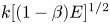 $k[(1-\beta )E]^{1/2}$: the rescaled neutral curves collapse for
 $\beta \rightarrow 1$.

4.2. Critical parameters and scalings
Figures 23(a), 23(c) and 23(d) show the variation of critical parameters  $Re_c$,
 $k_c$ and
 $c_{r,c}$ with
 $E (1-\beta )$ for different
 $\beta$. Irrespective of
 $\beta$, the critical parameters conform to scaling laws for small
 $E(1-\beta )$; thus,
 $Re_c \propto (E(1-\beta ))^{-3/2}$,
 $k_c \sim (E(1-\beta ))^{-1/2}$ and
 $(1-c_{r,c}) \sim (1-\beta ) E$. Further, the curves for
 $\beta > 0.9$ collapse onto a universal curve in this limit (as was expected from the findings of the previous section in the dual limit
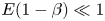 $E(1-\beta ) \ll 1$,
 $(1-\beta ) \ll 1$. The collapse breaks down for
 $E(1-\beta ) > 0.05$, with the breakdown occurring at the point where the original neutral curves in the
 $Re$–
 $k$ plane start shifting upwards (after becoming two-lobed), with the lower lobe shrinking in size with increasing
 $E$ (figure 18). As
 $E (1-\beta )$ is increased,
 $Re_c$ reaches a minimum value and beyond a threshold value of
 $E (1-\beta )$, it increases rather sharply indicating the flow to be stable beyond this threshold. However, this threshold shifts to higher
 $E(1-\beta )$ as
 $\beta \rightarrow 1$, and
 $Re_c$ therefore continues to decrease for
 $\beta \rightarrow 1$, with the lowest
 $Re_c$ found being as small as
 $63$ (albeit for
 $E \sim 10$). The latter suggests that pipe flow of strongly elastic dilute polymer solutions can become unstable at an
 $Re$ much lower than that for their Newtonian counterparts. Figure 23(b) shows that
 $Re_c$ in figure 23(a) decreases approximately in a linear manner with
 $\beta$, although there appears to be an eventual deviation from linearity for the highest
 $\beta = 0.99$ analysed in this study. The aforementioned deviation from linearity suggests the approach of
 $Re_c$ to a finite lower bound regardless of
 $E$ or
 $\beta$, and that this lower bound is attained with
 $E(1-\beta )$ being finite. However, note that the corresponding
 $E$ diverges as
 $1/(1-\beta )$ for
 $\beta \rightarrow 1$, implying that the flow only becomes unstable for a very high
 $W$ in this limit.
Variation of critical parameters with  $E (1-\beta )$ for
 $\beta$ ranging from
 $0.4$ to
 $0.99$. (a) Plot of
 $Re_c$ versus
 $E(1-\beta )$, (b) the minima of
 $Re_c$ of (a) decreases approximately in a linear manner with
 $\beta$, but appears to approach a finite value as
 $\beta \rightarrow 1$, whereas the corresponding
 $E$ diverges as
 $\beta \rightarrow 1$, (c)
 $k_c$ versus
 $E(1-\beta )$ and (d)
 $(1-c_{r,c})$ versus
 $E(1-\beta )$. Here
 $Re_c$ and
 $k_c$ follow the scalings
 $Re_c\propto [E(1-\beta )]^{-3/2}$ and
 $k_c\propto [E(1-\beta )]^{-1/2}$, respectively, below a critical value of
 $E(1-\beta )$.

The scalings for the parameters ( $Re$,
 $c_r$,
 $k$) with
 $E$ for
 $E\ll 1$, found previously, may also be justified using a scaling analysis for the boundary layer near the centreline, as briefly outlined in Garg et al. (Reference Garg, Chaudhary, Khalid, Shankar and Subramanian2018). In the limit
 $Re \gg 1$,
 $E\ll 1$, there is a ‘core’ region around the centreline with (dimensionless) extent
 $\delta \ll 1$, where inertial, elastic and viscous stresses are equally important. The scalings for
 $Re, k, \delta$ and
 $c_r$ in terms of
 $E$ can be derived by rescaling (2.8)–(2.14) in the region near the centreline as follows. The radial coordinate
 $r$ near the centreline can be expressed as
 $r=\delta \xi$, with
 $\xi \sim O(1)$. For
 $E\ll 1$, our numerical results show that
 $k_c$ becomes large for
 $E \ll 1$, and so we set
 $k \sim \delta ^{-1}$ in the analysis, as suggested by the continuity equation. The eigenvalue
 $c$ approaches unity in the said limit, and as
 $r \rightarrow 0$,
 $U\sim 1$,
 $(U-c) \sim \delta ^2$ and we therefore expand
 $c$ as
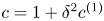 $c=1+\delta ^2c^{(1)}$. The derivatives near the centreline get rescaled as
 ${\mathrm {d}}/{\mathrm {d}r}=({1}/{\delta })({\mathrm {d}}/{\mathrm {d}\xi }) \equiv \delta ^{-1} {D_1}$.
The base-flow profile becomes  $U = 1-r^2 \equiv 1-\delta ^2\xi ^2$, and (2.8)–(2.14) take the following forms near the centreline:
 \begin{equation} \delta^{{-}1}(\mathrm{D_1}+\xi^{{-}1})\tilde{v}_r+\mathrm{i}k\tilde{v}_z=0, \end{equation}
 \begin{align} -\mathrm{i}k\delta^2(c^{(1)}+\xi^2)\tilde{v}_r &={-}\delta^{{-}1}\mathrm{D_1}\tilde{p}+\{\delta^{{-}1} (\mathrm{D_1}+\xi^{{-}1})\tilde{\tau}_{rr} \nonumber\\ &\quad +\mathrm{i}k\tilde{\tau}_{rz}-\delta^{{-}1}\xi^{{-}1}\tilde{\tau}_{\theta\theta}\} + \beta Re^{- 1}\delta^{{-}2}\mathrm{L_1}\tilde{v}_r, \end{align}
 \begin{align} -\mathrm{i}k\delta^2(c^{(1)}+\xi^2)\tilde{v}_z-2\delta\xi\tilde{v}_r &={-}\mathrm{i}k\tilde{p}+[\delta^ {{-}1}(\mathrm{D_1}+\xi^{{-}1})\tilde{\tau}_{rz} \nonumber\\ &\quad +\mathrm{i}k\tilde{\tau}_{zz}] +\beta Re^{{-}1}\delta^{{-}2}(\mathrm{L_1}+\xi^{{-}2})\tilde{v}_z, \end{align}
 \begin{equation} \{1- \mathrm{i}kW\delta^2(c^{(1)}+\xi^2)\} \tilde{\tau}_{rr} = 2(1-\beta)Re^{{-}1}(\delta^{- 1}\mathrm{D_1}-2W\mathrm{i}k\delta\xi)\tilde{v}_r, \end{equation}
 \begin{align} & \{1- \mathrm{i}kW\delta^2(c^{(1)}+\xi^2)\} \tilde{\tau}_{rz} +2W\delta\xi\tilde{\tau}_{rr} = (1- \beta)Re^{{-}1} [\{\mathrm{i}k \nonumber\\ &\quad -2W(1-\xi\mathrm{D_1}+4W\mathrm{i}k\delta^2\xi^2)\}\tilde{v}_r+(\delta^{{-}1}\mathrm{D_1}-2W \mathrm{i}k\delta\xi)\tilde{v}_z], \end{align}
 \begin{equation} \{1- \mathrm{i}kW\delta^2(c^{(1)}+\xi^2)\} \tilde{\tau}_{\theta\theta} = 2(1-\beta)Re^{{-}1}\delta^ {{-}1}\xi^{{-}1}\tilde{v}_r, \end{equation}
 \begin{align} & \{1- \mathrm{i}kW\delta^2(c^{(1)}+\xi^2)\} \tilde{\tau}_{zz} +4W\delta\xi\tilde{\tau}_{rz} = 2(1- \beta)Re^{{-}1} [{-}8W^2\delta\xi\tilde{v}_r \nonumber\\ &\quad +\{\mathrm{i}k-2W\delta\xi(\delta^{{-}1}\mathrm{D_1}-4W\mathrm{i}k\delta\xi)\}\tilde{v}_z], \end{align}
where  $\mathrm {L_1}=(\mathrm {D_1}^2+\xi ^{-1}\mathrm {D_1}-\xi ^{-2}-k^2\delta ^{2})$. In the
 $r$-momentum equation, a balance of inertial stresses and solvent viscous stresses gives
 $\delta \sim Re^{-1/3}$. The left-hand side of the linearized constitutive equations reveal that in order for the elastic and viscous contributions to be of the same order, we require
 $W \sim \delta ^{-1}$ or, after using
 $\delta \sim Re^{-1/3}$,
 $Re \sim E^{-3/2}$. We thus obtain the following scaling relationships for
 $Re \gg 1$,
 $E \ll 1$, along the neutral curve:
 \begin{equation} \delta \sim Re^{{-}1/3},\quad k\sim Re^{1/3},\quad Re\sim E^{{-}3/2},\quad \text{and}\quad (1-c)\sim Re^{{-}2/3}. \end{equation}
As shown in figure 24, the eigenfunctions for different  $Re$ and
 $k$ along the lower branch of the neutral curve do exhibit a collapse when plotted as a function of the boundary layer coordinate
 $\xi$. It is also possible to obtain the following scalings for a fixed
 $k$ by rescaling the (2.8)–(2.14):
 \begin{equation} \delta\sim Re^{{-}1/4},\quad Re\sim E^{{-}2},\quad (1-c)\sim Re^{{-}1/2},\quad \text{and}\quad \tilde{v}_z \sim Re^{1/4}\tilde{v}_r. \end{equation}
These scalings are illustrated by the collapse of the  $\tilde {v}_r$ and
 $\tilde {v}_z$ eigenfunctions, corresponding to the unstable mode, as shown in figure 25 for a few selected pairs (
 $Re, W$) that are large enough to justify the limit
 $(Re, W)\rightarrow \infty$ such that
 $Re \sim E^{-2}$.
Collapse of eigenfunctions at different  $Re$ and
 $k$ along the lower branch of the neutral curve for
 $\beta = 0.4$: (a)
 $\tilde {v}_z$ and (b)
 $\tilde {v}_r$. The eigenvalues (with
 $c_i = 0$) for which the rescaled eigenfunctions are shown are
 $c = 0.996707, 0.995912, 0.995131, 0.994367$ and
 $0.993621$, respectively.

Collapse of eigenfunctions at different  $Re$ and
 $E$, but for a fixed
 $k = 1$ for (a) axial velocity
 $\tilde {v}_z$ and (b) scaled radial velocity
 $Re^{1/4} \tilde {v}_r$, on scaled radial axis in the limit
 $Re\rightarrow \infty$ and
 $W\rightarrow \infty$ for a fixed
 $W/Re^{1/2}$ and
 $\beta =0.5$, corresponding to the eigenvalues
 $c=0.994842+0.000112i,0.996321+0.000103i,0.996985+0.000093i$ and
 $0.997383+0.000085i$, respectively.

Figure 26(a) shows that the critical Reynolds number ( $Re_c$) and critical wavenumbers (
 $k_c$) for different values of
 $E$ and
 $(1-\beta )E$ follow the scalings
 $Re_c\propto [(1-\beta )E]^{-3/2}$ and
 $k_c\propto [(1-\beta )E]^{-1/2}$ for
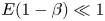 $E(1-\beta ) \ll 1$.
We had earlier reported (Garg et al. Reference Garg, Chaudhary, Khalid, Shankar and Subramanian2018) that
 $Re_c$ diverges weakly as
 $\beta ^{-1/4}$ for
 $\beta \rightarrow 0$, based on results extending down to a
 $\beta$ of
 $0.025$. However, new results for lower values of
 $\beta$ (down to
 $10^{-3}$) in figure 26(b) show that
 $Re_c$ does not diverge as
 $\beta ^{-1/4}$, but appears instead to diverge more weakly, or perhaps even asymptote to a constant. Thus far, we have not found any unstable mode in the UCM limit for the corresponding
 $Re$ and
 $E$. However, note that the structure of the centre mode changes qualitatively for the smallest
 $\beta$, characterized by the onset of small-scale oscillations (Chaudhary et al. Reference Chaudhary, Garg, Shankar and Subramanian2019), and our efforts thus far prevent us from discriminating between
 $Re_c$ approaching a constant with regards to a weak divergence in the said limit.
(a) Rescaled critical parameters  $Re_c E^{3/2}$ and
 $k_c E^{1/2}$ versus
 $(1-\beta )$ fall on straight lines of slopes
 $-3/2$ and
 $-1/2$, respectively, for smaller
 $(1-\beta )$ implying
 $Re_c\propto [(1-\beta )E]^{-3/2}$ and
 $k_c\propto [(1-\beta )E]^{-1/2}$ in the limit
 $\beta \rightarrow 1$. (b) Variation of critical parameters
 $Re_c$ and
 $k_c$ with
 $\beta$ for
 $E=0.01$.

4.3. Role of stress diffusion on the unstable centre mode
As discussed in the introduction, artificial stress diffusion is often used for regularization in DNS studies of viscoelastic flows (Sureshkumar & Beris Reference Sureshkumar and Beris1995; Sureshkumar et al. Reference Sureshkumar, Beris and Handler1997; Lopez et al. Reference Lopez, Choueiri and Hof2019). Recently, it has been shown that this additional diffusivity can qualitatively affect the stress dynamics (Gupta & Vincenzi Reference Gupta and Vincenzi2019), even to the extent of suppressing signatures associated with EIT (Sid et al. Reference Sid, Terrapon and Dubief2018). In this section, therefore, we briefly examine the effect of stress diffusion on the onset of the centre mode instability. The constitutive equation for the polymeric stress, (2.2), is now augmented with the stress diffusion term:
 \begin{align} W \left( \frac{\partial \boldsymbol{T}}{\partial t} + (\boldsymbol{v} \boldsymbol{\cdot} \boldsymbol{\nabla}) \boldsymbol{T} -\boldsymbol{T}\boldsymbol{\cdot} ( \boldsymbol{\nabla} \boldsymbol{v} ) - ( \boldsymbol{\nabla} \boldsymbol{v} )^{\textrm{T}} \boldsymbol{\cdot} \boldsymbol{T} \right) + \boldsymbol{T} + \frac{D \lambda}{R^2} \nabla^2 \boldsymbol{T} = \frac{1-\beta}{Re} \{\boldsymbol{\nabla} \boldsymbol{v} +( \boldsymbol{\nabla} \boldsymbol{v})^{\textrm{T}}\},\end{align}
where  $D$ is the stress diffusivity. El-Kareh & Leal (Reference El-Kareh and Leal1989) showed that the stress diffusion term owes its origin to the translational diffusion of the polymer molecules and estimated the diffusivity
 $D$ to be
 $O(10^{-12})\ \textrm {m}^2\ \textrm {s}^{-1}$. Using relaxation times
 $\lambda \sim 10^{-3}$ s reported in Chandra et al. (Reference Chandra, Shankar and Das2018) for polymer concentrations
 ${\sim }500$ ppm, and for tube diameters
 ${\sim }0.1$–
 $1$ mm, the dimensionless diffusivity
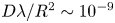 $D \lambda /R^2 \sim 10^{-9}$–
 $10^{-7}$. It is useful to represent diffusive effects using a Schmidt number
 $Sc \equiv \nu /D = E /(D \lambda /R^2)$, with
 $Sc \rightarrow \infty$ representing the absence of diffusion. The linearized equations for viscoelastic pipe flow using (4.16) were solved using a spectral method. Additional boundary conditions are now required for the stress components. At the pipe wall (
 $r=1$), the stress equation is imposed without the diffusivity, whereas a regularity condition for the stress is imposed at the centreline (Beris & Dimitropoulos Reference Beris and Dimitropoulos1999; Lopez et al. Reference Lopez, Choueiri and Hof2019). A finite stress diffusivity regularizes the continuous spectrum modes and leads to an additional family of stable diffusive modes. The decay rate of this family increases with increasing
 $(D \lambda /R^2)$. However, the discrete modes existing in the absence of stress diffusion are only weakly perturbed for small values of the diffusivity
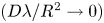 $(D \lambda /R^2 \rightarrow 0)$.
Figure 27 shows that the  $Re$ for onset of the centre mode instability increases with increasing (
 $D \lambda /R^2$), implying that the stress diffusivity has a stabilizing effect; for
 $D \lambda /R^2 \rightarrow 0$, the onset becomes independent of the diffusivity, approaching the values shown in figure 27. The threshold diffusivity for stabilization is seen to depend on
 $E$ and
 $\beta$. Importantly, the instability continues to exist for the experimentally relevant values of
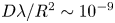 $D \lambda /R^2 \sim 10^{-9}$–
 $10^{-7}$, but would be suppressed at much larger values of
 $D \lambda /R^2 \sim 10^{-4}$–
 $10^{-2}$ (or, equivalently,
 $Sc < 1000$, for
 $E \sim 0.1$) used in earlier DNS studies (Sureshkumar & Beris Reference Sureshkumar and Beris1995; Sureshkumar et al. Reference Sureshkumar, Beris and Handler1997; Lopez et al. Reference Lopez, Choueiri and Hof2019). Thus, consistent with the results of Sid et al. (Reference Sid, Terrapon and Dubief2018), the results of figure 27 reinforce the importance of using simulation techniques, which avoid an artificially enhanced diffusivity, to access the axisymmetric structures associated with the centre-mode instability.
The effect of stress diffusion (characterized by  $D \lambda /R^2$) on the threshold
 $Re$ required for onset of instability at different
 $E, \beta$ and
 $k$.

4.4. Comparison with recent experimental studies and DNS
4.4.1. Comparison with experiments
We have replotted, in figure 28, the results of Samanta et al. (Reference Samanta, Dubief, Holzner, Schäfer, Morozov, Wagner and Hof2013) for the transition Reynolds number  $Re_t$ as a function of
 $E(1-\beta )$, based on the reported viscosities and relaxation times of the different polymer solutions used in the experiments. The present theoretical results yield similar critical Reynolds numbers
 $Re_c$ only at much higher values of
 $E(1-\beta )$. Samanta et al. (Reference Samanta, Dubief, Holzner, Schäfer, Morozov, Wagner and Hof2013) estimated the relaxation time using the CaBER technique (Anna & McKinley Reference Anna and McKinley2001), in which the flow is extensional, and the polymer chains are highly stretched. However, the CaBER procedure is known to have some disadvantages in the estimation of relaxation time for polymers in low-viscosity solvents owing to inertia being neglected in the filament thinning dynamics. The CaBER relaxation time also exhibits a significant concentration dependence even below the nominal overlap concentration (Clasen et al. Reference Clasen, Plog, Kulicke, Owens, Macosko, Scriven, Verani and McKinley2006). The data for
 $Re_t$ from the experiments of Chandra et al. (Reference Chandra, Shankar and Das2018), also plotted in figure 28, shows good agreement with the theoretical
 $Re_c$; in that, both threshold
 $Re$ are of the same order of magnitude for comparable
 $E(1-\beta )$. Chandra et al. (Reference Chandra, Shankar and Das2018) used small-amplitude oscillatory strain experiments to infer the relaxation times; in contrast to CaBER, the polymer chains are not greatly perturbed about their equilibrium conformations. Although the threshold
 $Re$ from Chandra et al. (Reference Chandra, Shankar and Das2018) are comparable to theory, the latter predicts
 $Re_c \sim E^{-3/2}$ along the lower branch of the theoretical envelope, and
 $Re_t \sim E^{-1/2}$ in Chandra et al. (Reference Chandra, Shankar and Das2018). This difference in the scaling exponents could be due to shear thinning in the experiments, which can also significantly alter the parabolic nature of the base velocity profile. These effects are not accounted for in the Oldroyd-B model used in this study. The following scaling analysis examines the role of shear thinning on the scaling exponent characterizing the
 $Re_c$ versus
 $E$ behaviour for small
 $E$. We begin by noting the limiting behaviour of viscosity and relaxation time, for large
 $W$, for the more realistic FENE-P model, where shear thinning arises on account of the chains being finitely extensible (Bird, Dotson & Johnson Reference Bird, Dotson and Johnson1980):
 \begin{equation} \eta_1 \sim \eta (\dot{\gamma} \lambda)^{{-}2/3},\quad \text{and}\quad \lambda_1 = \lambda (\dot{\gamma} \lambda)^{{-}4/3}, \end{equation}
where  $\eta$ and
 $\lambda$ are viscosity and relaxation time at zero shear rate (
 $\dot {\gamma } = U/R$). The effective Reynolds number
 $Re_1$ and Weissenberg number
 $W_1$, evaluated using the shear-rate dependent viscosity and relaxation time, are given in terms of those involving the corresponding zero-shear-rate quantities, as
 \begin{equation} Re_1 = \frac{\rho UR}{\eta_1} = E^{2/3}Re^{5/3},\quad \text{and}\quad W_1 = \frac{\lambda_1 U}{R}, \end{equation}
and the effective elasticity number  $E_1$ becomes
 \begin{equation} E_1 = \frac{W_1}{Re_1}= \frac{\lambda_1 \eta_1}{\rho R^2} = E^{{-}1}Re^{{-}2}. \end{equation}
We now postulate that the scaling for  $Re_c$ determined above for an Oldroyd-B fluid, is valid for a FENE-P fluid as well, but with
 $Re_1$ and
 $E_1$ replacing
 $Re$ and
 $E$ in order to account for the shear-rate dependence of viscosity and relaxation time. Using (4.18a,b)–(4.19) in the theoretical scaling
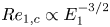 $Re_{1,c} \propto E_{1}^{-3/2}$ gives
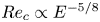 $Re_c \propto E^{-5/8}$; the scaling exponent now being closer to that (
 $-1/2$) observed in experiments (Chandra et al. Reference Chandra, Shankar and Das2018, Reference Chandra, Shankar and Das2020). A similar argument has been used earlier to successfully account the effect of shear thinning on the onset of inertialess elastic instability in Taylor–Couette flow (Larson, Muller & Shaqfeh Reference Larson, Muller and Shaqfeh1994).
Comparison of the present theoretical predictions with experimental results of Samanta et al. (Reference Samanta, Dubief, Holzner, Schäfer, Morozov, Wagner and Hof2013) and Chandra et al. (Reference Chandra, Shankar and Das2018).

4.4.2. Comparison with DNS of Lopez et al. (2019)
The recent DNS study by Lopez et al. (Reference Lopez, Choueiri and Hof2019) on viscoelastic pipe flow used the FENE-P model and showed that at a fixed  $Re = 3500$, the flow fully relaminarizes as
 $W$ is increased, and at even larger
 $W$, the laminar state again becomes unstable, with the post-instability friction factor approaching the MDR asymptote. In figure 29, we show the neutral stability curve in the
 $W$–
 $k$ plane corresponding to the centre mode instability for
 $Re = 3500$ and
 $\beta = 0.9$ (parameters corresponding to the DNS of Lopez et al. Reference Lopez, Choueiri and Hof2019), according to which the flow is unstable in the range
 $176.9 <W<4783.6$. The closed loop in the
 $W$–
 $k$ plane, at a fixed
 $Re = 3500$, arises because the centre mode instability is absent both in the low- and high-
 $W$ limits, as can be inferred from the corresponding neutral curves in the
 $Re$–
 $k$ plane shown in figure 18(b). The range of
 $W$ corresponding to the
 $W$–
 $k$ loop where the linear instability of the centre mode is found is significantly higher than the range (
 $16<W<80$) over which EIT was observed in the simulations of Lopez et al. (Reference Lopez, Choueiri and Hof2019). However, the Oldroyd-B model used here does not account for shear thinning effects inherent in the FENE-P model used in their simulations. More work is thus needed to address these discrepancies between the theoretical predictions and experimental and/or DNS studies.
Neutral stability curve in the  $W$–
 $k$ plane at fixed
 $Re = 3500$ and
 $\beta = 0.9$; the region inside the loop is unstable.

5. Conclusion and outlook
The present work builds on our earlier effort (Garg et al. Reference Garg, Chaudhary, Khalid, Shankar and Subramanian2018) to provide the first comprehensive set of results from a linear stability analysis of viscoelastic pipe flow using the Oldroyd-B model. In contrast to the prevailing view, and in direct contrast to its Newtonian counterpart, pipe flow of an Oldroyd-B fluid is unstable to infinitesimal perturbations. The unstable eigenfunction is a centre mode with phase speed close to the maximum of the base-state flow. We provide a detailed description of the emergence and nature of the unstable centre mode, and its relation to the CS in the linearized spectrum. Crucially, despite the phase speed being close to unity (the rationale behind the ‘centre mode’ terminology), the eigenfunctions for the unstable mode are not localized near the centreline in most of the parameter space, especially the region accessible to experiments. A bit surprisingly, perhaps, the flow appears to be stable in the limit of a UCM fluid, implying that the destabilizing mechanism involves a subtle interplay of fluid inertia, elasticity and solvent viscous effects. In the asymptotic limit corresponding to dilute polymer solutions ( $(1-\beta ) \ll 1$ and
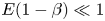 $E (1-\beta ) \ll 1$), consistent with scaling arguments, the numerical results show that the critical Reynolds number scales as
 $Re_c \sim (E (1-\beta ))^{-3/2}$, while the critical wavenumber scales as
 $k_c \sim (E (1-\beta ))^{-1/2}$. The radial lengthscale is now comparable with
 $k_c^{-1}$, so that the unstable eigenfunction in this limit does become confined to a thin region in the vicinity of the pipe centreline.
For  $E$ and
 $\beta$ pertaining to the experiments of Samanta et al. (Reference Samanta, Dubief, Holzner, Schäfer, Morozov, Wagner and Hof2013) with polymer concentrations greater than
 $300$ ppm, where the authors did observe the transition to be supercritical, results from our linear stability theory yield much higher transition
 $Re$ than the experiments. Equivalently, our results do predict a threshold
 $Re$ of
 $O(800)$, that observed for the 500 ppm solution in Samanta et al. (Reference Samanta, Dubief, Holzner, Schäfer, Morozov, Wagner and Hof2013), but only at much higher
 $E$. This discrepancy could perhaps be attributed to artifacts related to the CaBER procedure used by Samanta et al. (Reference Samanta, Dubief, Holzner, Schäfer, Morozov, Wagner and Hof2013) to characterize the relaxation time. This procedure is known to lead to a spurious underestimation of the relaxation time (recall that the elasticity number
 $E$ is proportional to the polymer relaxation time) for solutions well below the nominal overlap concentration; there might be additional problems arising from use of low-viscosity fluids (Clasen et al. Reference Clasen, Plog, Kulicke, Owens, Macosko, Scriven, Verani and McKinley2006). However, our theoretical predictions are broadly consistent with the observations of Chandra et al. (Reference Chandra, Shankar and Das2018), who used small-amplitude oscillatory strain experiments to infer the relaxation time, wherein the polymer chains are not greatly perturbed about their equilibrium conformations. In their rheological characterization, the solvent viscosity was significantly enhanced to enable a measurable signal, while maintaining a fixed concentration in the dilute regime (unlike CaBER). For the range of
 $E$ and
 $\beta$ corresponding to the latter experiments, linear stability theory predicts
 $Re_c \sim 10^2$–
 $10^3$, whereas experiments report
 $Re_t \sim 800\text {--}1000$. However, observations seem to satisfy the scaling relation
 $Re_t \sim (E (1-\beta ))^{-1/2}$ in contrast to the
 $-3/2$ exponent predicted by our theory (see figure 23a). One aspect that could be relevant in experiments, but not accounted for in the Oldroyd-B model, is shear thinning. Based on a scaling analysis for the FENE-P model that incorporated the asymptotic behavior of the relaxation time, and the resulting shear thinning, for large
 $W$, the aforementioned scaling exponent changes from
 $-3/2$ to
 $-5/8$, the latter being closer to the experimental exponent of
 $-1/2$. Nevertheless, more work is needed to reconcile theoretical predictions and observations, in terms of an accurate characterization of the polymer relaxation time (in the dilute regime), a careful detection of the onset of transition by multiple means (such as PIV and pressure-drop measurements), and by using realistic constitutive models (in the stability analysis) that extend across the overlap concentration, accounting for dynamics in both the dilute and semi-dilute regimes (Prabhakar et al. Reference Prabhakar, Gadkari, Gopesh and Shaw2016).
Prior to the present work, and notwithstanding a few experimental and simulation efforts referred to in the Introduction (for instance, Samanta et al. Reference Samanta, Dubief, Holzner, Schäfer, Morozov, Wagner and Hof2013; Choueiri et al. Reference Choueiri, Lopez and Hof2018; Lopez et al. Reference Lopez, Choueiri and Hof2019), the prevailing understanding of stability of viscoelastic flows and turbulent drag reduction was largely predicated on an elastic modification of the Newtonian transition scenario. The latter is known to be subcritical, wherein the actual transition is believed to be preceded by the appearance of (nonlinear) three-dimensional ECSs. As  $Re$ is increased, the laminar basin of attraction shrinks, with the concomitant appearance of more unstable ECSs. The turbulent trajectory is proposed to sample the phase space of such solutions in a chaotic manner (Budanur et al. Reference Budanur, Short, Farazmand, Willis and Cvitanović2017); note that the emergence of a sustained turbulent state, beyond a finite threshold
 $Re$, requires spatial–temporal dynamics that includes splitting and merging of localized ECS solutions (Avila et al. Reference Avila, Moxey, De Lozar, Barkley and Hof2011; Chantry, Willis & Kerswell Reference Chantry, Willis and Kerswell2014; Barkley Reference Barkley2016). The work of Graham and co-workers (Stone et al. Reference Stone, Waleffe and Graham2002; Stone & Graham Reference Stone and Graham2003; Stone et al. Reference Stone, Roy, Larson, Waleffe and Graham2004; Li & Graham Reference Li and Graham2007; Graham Reference Graham2014) explored in detail the effect of viscoelasticity on the above scenario. Specifically, Li & Graham (Reference Li and Graham2007) have shown that viscoelasticity suppresses the appearance of the relatively simple (travelling waves) ECS in channel flow. An extrapolation, entailing an assumption that viscoelasticity has a similar effect on the other ECSs, with a non-trivial time dependence, implies that the onset of the subcritical transition is delayed by viscoelasticity. As mentioned in § 1.3, this conclusion has some experimental support, in that the forced transition was delayed at lower polymer concentrations (Samanta et al. Reference Samanta, Dubief, Holzner, Schäfer, Morozov, Wagner and Hof2013; Chandra et al. Reference Chandra, Shankar and Das2018). Note, in contrast, that the threshold
 $Re$ for natural transition decreased over the same range of polymer concentrations, suggesting a destabilizing effect of elasticity on the presumably more complex scaffold of ECSs underlying the turbulent state at higher
 $Re$; this apparent dual role of elasticity, at the smallest
 $E$, has not been addressed in existing literature. The transition scenario at higher
 $E$, apart from being at lower
 $Re$, appears to have a fundamentally different character, being independent of external perturbations. Our analysis, consistent with these observations, shows that pipe flow is unstable to infinitesimal disturbances at sufficiently high
 $E$. Results from recent computations (Sid et al. Reference Sid, Terrapon and Dubief2018) emphasize the importance of 2D (span-wise oriented) structures in the elasto-inertial turbulent state for channel flow, in marked contrast to the 3D Newtonian scenario, reinforcing the notion of an underlying instability to axisymmetric perturbations examined here. Importantly, the nature of the elasto-inertial coherent structures identified in DNS of both viscoelastic channel and pipe flow (Sid et al. Reference Sid, Terrapon and Dubief2018; Lopez et al. Reference Lopez, Choueiri and Hof2019) are quite similar, pointing to a generic mechanism operative in both these geometries, again consistent with our own finding of an analogous centre mode instability in channel flow (Garg et al. Reference Garg, Chaudhary, Khalid, Shankar and Subramanian2018; Khalid et al. Reference Khalid, Chaudhary, Garg, Shankar and Subramanian2021).
Our study is a clear call for a reassessment of the current understanding of turbulent drag reduction by polymers, in particular, of the nature of the MDR regime and its relation to both the laminar and (Newtonian) turbulent states. Recent experimental results of Choueiri et al. (Reference Choueiri, Lopez and Hof2018) explicitly demonstrate the link between EIT and the MDR regime, by showing that the same physical mechanisms underlie the two states (at least for the moderate  $Re$ accessed in the experiments). Both experiments and DNS (Choueiri et al. Reference Choueiri, Lopez and Hof2018; Lopez et al. Reference Lopez, Choueiri and Hof2019; Shekar et al. Reference Shekar, McMullen, Wang, McKeon and Graham2019) have also shown that MDR can also be reached via a direct pathway from the laminar state of a polymer solution, without entering the Newtonian turbulent regime. Thus, the terminology of ‘drag reduction’ is somewhat ambiguous: the MDR state was traditionally viewed as a drag-reduced state from Newtonian turbulence upon addition of polymers. Based on the above picture, and the linear instability identified in this work, we conjecture that the aforementioned direct pathway to MDR could be achieved via a nonlinear saturation of the elasto-inertial centre mode instability of viscoelastic pipe flow, with a concomitant mild drag enhancement relative to the laminar state. The eigenfunctions corresponding to the unstable mode identified in this study should form a template for future nonlinear studies aimed at identifying novel nonlinear elasto-inertial structures that might play an important role in understanding the nature of the MDR state at large elasticity numbers. As a first step in this direction, results from a weakly nonlinear analysis (along the lines of Stuart Reference Stuart1960; Watson Reference Watson1960), which are largely consistent with the conclusions of the linear stability analysis presented here, will be reported in a future communication.
Based on the above discussion, it is useful to organize our understanding of the various possible transition scenarios in viscoelastic pipe flows in the form of a ‘phase diagram’ in  $Re$–
 $W$ (and
 $\beta$) space. This is shown as a schematic in figure 30 for a fixed
 $\beta \sim 0.5$ and higher; for
 $\beta \rightarrow 0$,
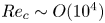 $Re_c \sim O(10^4)$ (see figure 26b), and it is not clear whether the linear instability (at such high
 $Re$) would continue to be practically relevant. Note that an experimental pathway representing an increase in flow rate (for a given pipe diameter and polymer solution) will appear as an oblique line (with slope
 $E = W/Re$) in the
 $Re$–
 $W$ plane (Graham Reference Graham2014; Xi Reference Xi2019). It helps to consider two limiting sequences in this plane. The first corresponds to increasing
 $Re$ at
 $W = 0$: the Newtonian transition. The subcritical nature of this transition and the underlying role of the ECSs is now relatively well established. The effect of viscoelasticity on this picture has been discussed in the earlier paragraph, the main idea being that the suppression of the ECSs by elasticity, at
 $Re$ greater than the Newtonian threshold (
 $Re \sim 2000$), has been interpreted as the reason for a delayed transition; the regime of existence of the Newtonian ECSs for
 $W = 0$, and the postponement of this regime with increasing
 $W$ is marked with a dashed red line near the
 $Re$-axis in figure 30. It is worth noting that despite the sharp contrast in the linear (modal) eigenfunctions for pipe and channel flow (the absence of the TS wall mode in pipe flow being an example), the Newtonian ECSs have a similar character across all of the canonical shearing flows, consisting of counter-rotating vortices and stream-wise streaks in all cases. Thus, the extrapolation of the effects of viscoelasticity to the pipe geometry, based on the domain of existence of finite-
 $W$ ECSs in the channel geometry, is reasonable. Nevertheless, there is a need to examine the nature of elastically modified pipe flow ECSs, as a function of
 $W$, in order to render the arguments quantitative. As already indicated, such ECS-based arguments are no longer valid at higher
 $E$ when the Newtonian ECSs are absent. Furthermore, and as indicated, the initial reduction in threshold
 $Re$ for the natural transition with increasing
 $E$ (Samanta et al. Reference Samanta, Dubief, Holzner, Schäfer, Morozov, Wagner and Hof2013) is already indicative of the ECS dynamics in the presence of viscoelasticity being more complicated, and emphasizes the need for more work.
Schematic representation of various transition scenarios in viscoelastic pipe flow in the  $Re$–
 $W$ (for a fixed
 $\beta$) plane. The boundaries shown using dotted red lines represent subcritical bifurcations, whereas the unstable boundary owing to the centre mode instability is shown using a continuous red line. The oblique blue lines indicate experimental paths in which flow rate is increased (in a pipe of a given diameter and for a given polymer solution) with
 $E = W/Re$ being constant;
 $E_2 > E_1$.

The understanding of the MDR regime attained at higher  $E$ (or higher
 $W$ with
 $Re$ fixed), shown schematically by the path
 $E_1$ in figure 30, was until recently based on a series of minimal (channel) flow unit simulations carried out by Graham and co-workers (Xi & Graham Reference Xi and Graham2010, Reference Xi and Graham2012; Graham Reference Graham2014; Xi Reference Xi2019). The hypothesis advanced was that of the dynamics in the MDR state corresponding to that of a largely unaltered Newtonian ‘edge state’, a marginal state whose stable manifold forms the boundary separating the laminar fixed point and the turbulent attractor. This edge state manifests as prolonged periods of so-called hibernating turbulence, characterized by subdued fluctuations and an associated weak stream-wise variation. The primarily Newtonian character of this edge state was proposed as an explanation for the independence of the MDR regime with respect to polymer characteristics. In effect, the originally unstable Newtonian edge state has been suggested to be stabilized at higher
 $E$. The connection between the disappearance of the ECSs in earlier work by Graham's group, and the subsequent appearance of a stabilized edge state at higher
 $E$, has not been clarified from a dynamical systems view point in terms of an appropriate viscoelastic state space (it is worth noting that, for the Newtonian case, most of the lower-branch travelling-wave solutions are known to lie on the aforementioned laminar–turbulent boundary, and are therefore edge states, albeit unstable). Importantly, however, the veracity of the above edge-state-based interpretation has been recently challenged by simulations in domains long enough to contain a puff (Lopez et al. Reference Lopez, Choueiri and Hof2019) where the hibernating state is found to give way to spatiotemporal intermittency, and subsequent relaminarization. However, for shorter streamwise domain lengths (yet twice as long as in Xi & Graham Reference Xi and Graham2010), similar to Xi & Graham (Reference Xi and Graham2010), Lopez et al. (Reference Lopez, Choueiri and Hof2019) did find low-drag periods to persist longer with increasing
 $W$, and the drag reduction reaching an apparent
 $W$-independent plateau, a plateau that precedes the eventual relaminarization. Although this plateau was interpreted as the MDR state by Xi & Graham (Reference Xi and Graham2010), it is now clear that the
 $W$-interval corresponding to this plateau is sensitively dependent on the length of the simulation domain, the plateau being virtually absent for the longer domains. Thus, the notion of a Newtonian edge-state underlying MDR requires further investigation.
At sufficiently high  $E$ (shown schematically by the path
 $E_2$ in figure 30), there is the possibility of the centre-mode instability (region in figure 30 demarcated by a continuous red curve) leading to a direct pathway from the laminar state to a nonlinear state characterized by essentially axisymmetric elasto-inertial structures that presumably arise from a saturation of the growing centre mode. These structures might then form the backbone of EIT dynamics. The identification of this pathway confirms the speculation of a linear instability at high
 $E$ (see figure 4 of Graham Reference Graham2014), thereby augmenting the various possible transition scenarios in the
 $Re$–
 $W$ plane. Based on the
 $E$-intervals identified here, for the centre-mode instability, there does appear to be a region in the
 $Re$–
 $W$ plane where the elastically modified (originally Newtonian) ECSs are absent and pipe flow is still linearly stable. In this regime, one might either expect dynamics corresponding to the Newtonian edge state, proposed by Graham and co-workers (described previously), or an entirely new set of subcritical elasto-inertial structures with an EIT trajectory sampling these novel elasto-inertial coherent states in a manner analogous to how one now understands a Newtonian turbulent trajectory to sample the multitude of Newtonian ECSs (Budanur et al. Reference Budanur, Short, Farazmand, Willis and Cvitanović2017). In fact, a novel EIT structure, with polymer stretch contours bearing some resemblance to an arrowhead configuration, has very recently been identified for viscoelastic channel flow, and has been shown to originate (subcritically) from the critical point corresponding to the onset of the centre-mode instability (Page, Dubief & Kerswell Reference Page, Dubief and Kerswell2020; Dubief et al. Reference Dubief, Page, Kerswell, Terrapon and Steinberg2020). In the latter regard, it is also worth mentioning the 2D nonlinear mechanism postulated by Shekar et al. (Reference Shekar, McMullen, Wang, McKeon and Graham2019), with the underlying structural signatures similar to the least-stable Newtonian TS mode. In contrast to the qualitative similarities in the nature of Newtonian pipe and channel ECSs, however, and as pointed out in § 3.3, differences in the axisymmetric pipe and two-dimensional channel flow viscoelastic spectra render this wall-mode-based mechanism untenable for pipe flow. This is because the centre mode in Newtonian pipe flow, while being stable, still has a decay rate smaller than that of the wall mode. Further, there is a significant regime in the
 $Re$–
 $W$ plane where the CS are the least stable. Thus, unlike the proposal of Shekar et al. (Reference Shekar, McMullen, Wang, McKeon and Graham2019) for channel flow, a novel subcritical elasto-inertial dynamics, in pipe flow, would seem to have to account for the dynamics of the continuous spectrum at leading order (Balmforth, Morrison & Thiffeault Reference Balmforth, Morrison and Thiffeault2013). Further, any additional dynamics related to the discrete modes would still appear to be dominated by the centre mode on account of its lower decay rate. Based on this qualitative picture, we have indicated (in figure 30) the two possible mechanisms in the region that separates the regimes corresponding to the centre-mode instability, and the subcritical ECS. Note that any pathway leading up to the EIT regime, at a fixed
 $Re$, involves a transition from coherent structures with stream-wise vorticity to those with span-wise vorticity.
Finally, at the highest  $E$, one approaches the second limiting sequence in figure 30, which is that of increasing
 $W$ at
 $Re = 0$, and therefore, concerns the inertia-less transition to elastic turbulence (Groisman & Steinberg Reference Groisman and Steinberg2000), which is believed to follow the traditional nonlinear route (Stuart Reference Stuart1960; Watson Reference Watson1960). van Saarloos and co-workers (Meulenbroek et al. Reference Meulenbroek, Storm, Bertola, Wagner, Bonn and van Saarloos2003, Reference Meulenbroek, Storm, Morozov and van Saarloos2004; Morozov & van Saarloos Reference Morozov and van Saarloos2005, Reference Morozov and van Saarloos2007), based on a viscoelastic analogue of the original Stuart–Landau expansion, have shown that inertia-less pipe flow undergoes a subcritical bifurcation to a nonlinear two-dimensional state (represented using a dotted red line near
 $Re = 0$ in figure 30); the same is true for plane Couette and Poiseuille flows. This scenario has found some support in experiments (Pan et al. Reference Pan, Morozov, Wagner and Arratia2013). These weakly nonlinear analyses are based on the existence of an unstable/weakly stable discrete mode well separated from the remainder of the spectrum. This is indeed true for inertia-less viscoelastic flows where the spectrum consists of a small number of discrete modes (Renardy & Renardy Reference Renardy and Renardy1986; Wilson et al. Reference Wilson, Renardy and Renardy1999), in addition to the CS. However, the spectrum becomes far more complicated with increasing
 $Re$, with there being no clear separation in the above sense (see figure 12a and those in Chaudhary et al. Reference Chaudhary, Garg, Shankar and Subramanian2019). In fact, for moderate
 $Re$ and for small but finite
 $E$, as pointed out above, there exist scenarios wherein no discrete modes are present above the continuous spectrum (e.g. for
 $E < 0.6$ and
 $Re = 500$,
 $\beta = 0.96$ in figure 5a), thereby necessitating the consideration of the CS at leading order in the nonlinear analysis. Clearly, therefore, the nonlinear mechanisms proposed by van Saarloos and co-workers are restricted to modest
 $Re$, and cannot serve as an explanation for transition to EIT.
In summary, our finding of a linear instability in viscoelastic pipe flow marks a possible paradigm shift from both classical and modern theoretical work on Newtonian fluids, by providing a natural explanation for the connection between the laminar state and the elasto-inertial state underlying the so-called MDR regime.
Acknowledgements
I.C. and P.G. contributed equally to this work.
Declaration of interests
The authors report no conflict of interest.