I. INTRODUCTION
Left-handed materials, which have negative permittivity and permeability do not exist in nature, but we can generate them artificially by reactive L and C lumped elements, hence the name metamaterial. The practical use of these materials causes right-handed (RH) parasitic effects, which makes them behave like composite right/left-handed (CRLH) structures. Metamaterials which are mainly dedicated for telecom applications are widely studied in the literature for both planar and lumped elements’ configurations [Reference Caloz and Itoh1–Reference Niu9] by mainly using simulation softwares such as ADS and HFSS.
The authors in [Reference Baudrand and N'gongo10–Reference Hajri, Hrizi and Sboui14] described the effectiveness of the wave concept iterative process (WCIP) method to treat purely planar structures effective in terms of precision and computing time. However, a theoretical study proceeded by a simulation before a realization in planar distributed or lumped circuits is required to obtain appreciable results. So, the reformulation of the iterative method to study structures with lumped element is necessary [Reference Azizi, Latrach, Raveu, Gharsallah and Baudrand15–Reference Baudrand, Azizi and Titaouine17]. This new approach to the WCIP method is generally based on electric and magnetic fields instead of current I and voltage V when working at a high frequency because the length of the circuit is higher than the wavelength and the current as well as voltage are both functions of time and space. But, if the length of the circuit is much smaller than the wavelength, it is easy to handle the values of I and V for circuits with lumped elements. A wave is a function of time and space, i.e. the two spatial and temporal domains. These domains are related to the frequency domain by applying the fast Fourier transform (FFT) and its inverse (IFFT). It is on this principle that the WCIP method works. The FFT, which is based on the samples of a signal, can be faithful to the shape of this signal if the well-known condition of Shannon is verified. This latter happens when the sampling frequency is higher than the frequency of two samples per period, which corresponds to the division of a one period by four, that is to say a length of cell lower than λ/4. The FFT makes a space sampling of the structure, which also corresponds to a time sampling of the propagated wave. This discretization leads to several cells per wavelength. Considering N cells by wavelength at a given frequency, these cells pass by the same states along one period of space. For example, the front of a wave (a state) crosses all the cells during one space period. Thus, a cell which passes by the N states (samples) during one space period can describe the behavior of N cells at a given moment, which enables us to base the study on only one cell. The passage between the two space and spectral domains allows us to calculate the current and the voltage at the input of each cell of our discretized structure and at each frequency of the work band. The knowledge of I and V allows us to calculate the input impedance and thereafter the coefficients of reflection and transmission. The new reformulated WCIP method is made for the study of the periodic structures with lumped elements. It can keep the advantages of the old method, namely execution time, precision and memory size, because both use the same iterative process. Moreover, compared with the planar technology, the use of circuits with lumped elements for the synthesis of the characteristics of metamaterials makes these structures more compact with an important reduction of the simulation time by keeping the possibility of visualizing the spatial distribution of the current and electric field.
This paper, which treats uni-dimensional lumped element circuits by the new approach to the WCIP method starts with a brief description of some equations of the new approach and the principle of the auxiliary source. Secondly, the current and voltage in an RH transmission lines (TL) are calculated using our method. Then, the periodicity of the reflection coefficient, which is a specificity of periodic networks, is discussed. After that, we present the choice of the adequate length of a unit cell using Bloch impedance. Finally, we study some cases of a CRLH circuit for pass/stop band filter and resonator applications.
II. THE WCIP AND THE PRINCIPLE OF THE AUXILIARY SOURCES
A) The wave iterative process (WCIP)
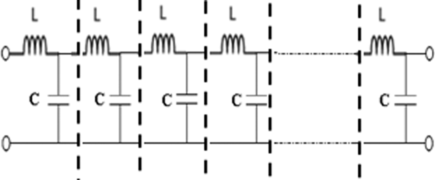
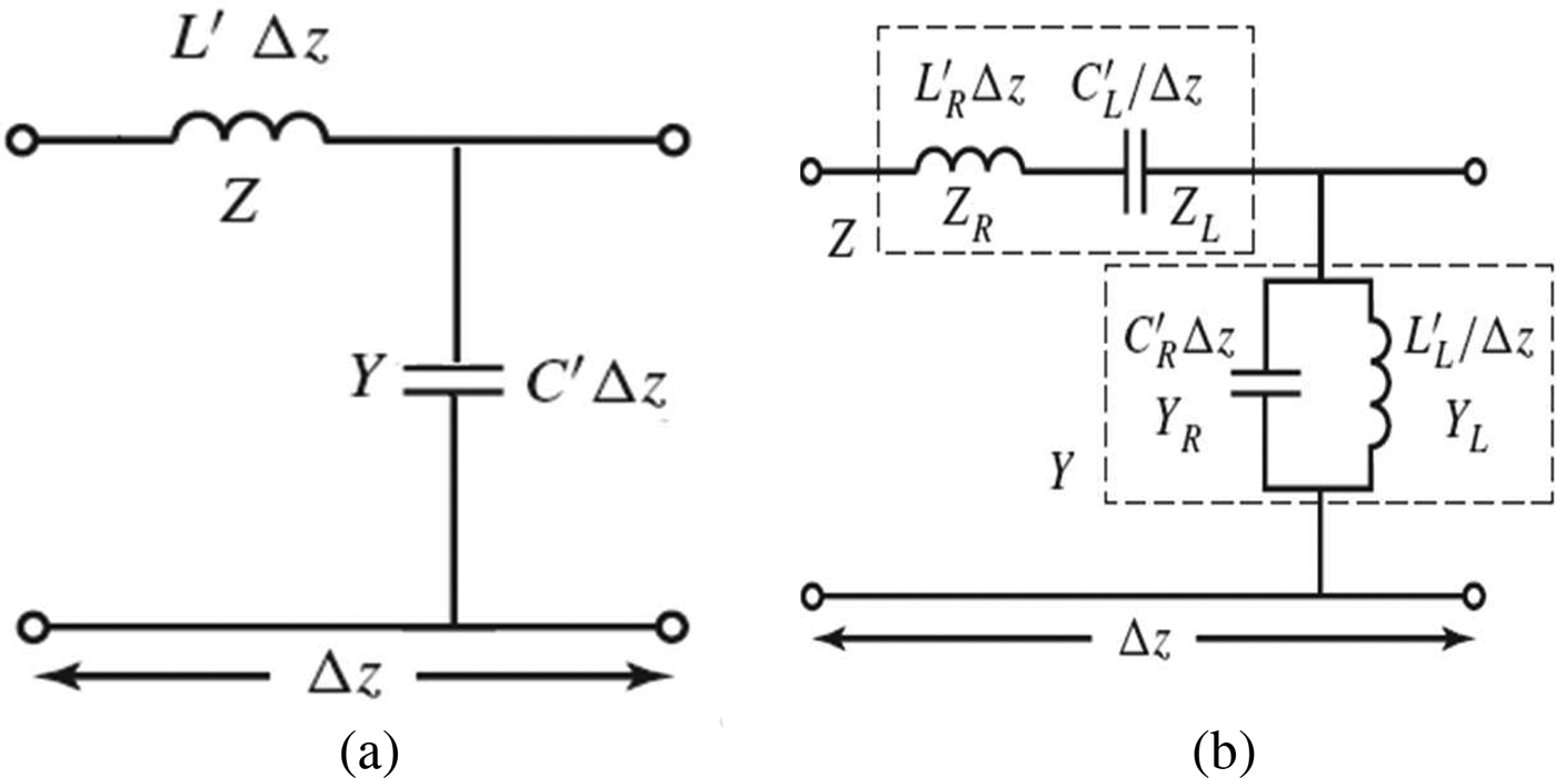
Uniform LC lossless transmission lines are equivalent to the distributed LC network shown in Fig. 1 and they are made up of many unit cells as shown in Fig. 2.
Distributed LC network.

Equivalent circuit model in a distributed LC network. (a) RH TL; (b) CRLH TL.

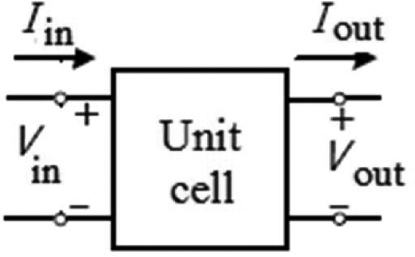
The new approach to the WCIP method has the advantage of working on one unit cell thanks to the periodic walls which surround it. This unit cell can be represented by the following diagram in Fig. 3.
Diagram of a unit cell.

The input voltage and current can be written as follows (1)
 $$\eqalign{& V_{in} = \sqrt {Z_0} (A_i + B_r), \cr & I_{in} = \displaystyle{1 \over {\sqrt {Z_0}}} (A_i - B_r).} $$
We can rewrite equation (1) in terms of the electric field E and current density J such that (2)
 $$\eqalign{& E = \sqrt {Z_0} (A_i + B_r), \cr & J = \displaystyle{1 \over {\sqrt {Z_0}}} (A_i - B_r),} $$
where A r and B r are the incident and reflected wave at the input of the cell, respectively, and Z 0 is the characteristic impedance of the line.
The wave iterative process [Reference Hajri, Hrizi and Sboui14] is based on the following equation (3)
 $$\left\{ \matrix{A_i = SB_r + A_0 \hfill \cr B_r = \Gamma A_i, \hfill} \right.$$
where A 0 is the incident wave emitted by the source of excitation and S and Г are the spatial and spectral reflection coefficients, respectively.
B) The principle of the auxiliary sources
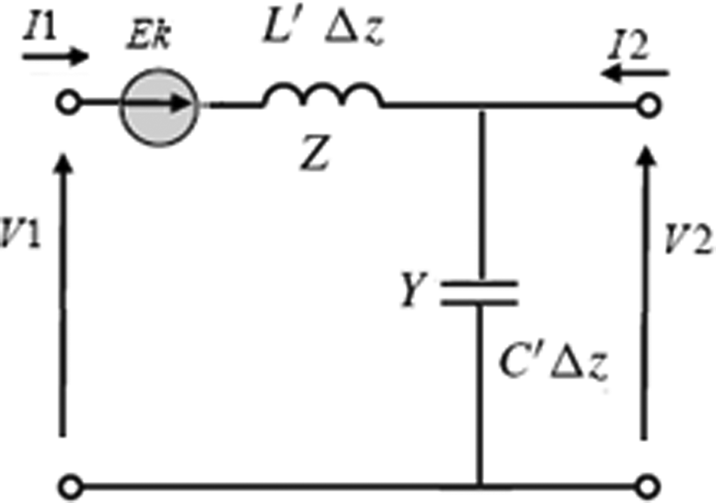
An auxiliary source (E K) is introduced by cell into the periodic structure. Each cell is surrounded by periodic walls separated by an electrical angle theta. In its environment, each auxiliary source passes by N states during the time of one space period, which helps to describe the states of all cells constituting the structure at a given moment t. So, we can describe the behavior of all the structure by describing that of one cell. An auxiliary source can be replaced by an impedance according to the desired application. Each RH unit cell containing an auxiliary source is presented in Fig. 4.
Unit-cell circuit in RH TL.

Based on the Floquet's theorem, we can easily calculate E K as a function of the elements of the unit circuit [Reference Azizi, Latrach, Raveu, Gharsallah and Baudrand15] as follows (4):
 $$E_K = - ZI_1 + \displaystyle{{{\left( {e^{ - j\beta \;{\rm d}z} - 1} \right)}^2} \over {Y \times e^{ - j\beta \;{\rm d}z}}}I_1.$$
From (4), we deduce the impedance viewed by the auxiliary source as follows (5):
 $$Z_\theta = - Z + \displaystyle{{{\left( {e^{ - j\theta} - 1} \right)}^2} \over {Y \times e^{ - j\theta}}}, $$
where θ is the electrical length of a unit cell at a given frequency. It expresses one state of the auxiliary source using the following equation (6):
 $$\theta = \displaystyle{{2\pi} \over \lambda} {\rm d}z;\quad \,{\rm d}z\;{\rm is}\;{\rm the}\;{\rm length}\;{\rm of}\;{\rm a}\;{\rm unit}\;{\rm cell}{\rm.} $$
In other words, θ also represents the spatial dephasing between two cells in the periodic network.
On the auxiliary source, the reflection coefficient at the state θ can be calculated as follows (7):
 $$\Gamma _{_\theta} = \displaystyle{{Z_\theta - Z_0} \over {Z_\theta + Z_{_0}}}. $$
The auxiliary source can represent an on/off switch. Therefore, the spatial reflection coefficient is given by (8)
 $$S = \left\{ {\scriptstyle - 1\;{\rm short}\;{\rm circuit} \hfill \atop \scriptstyle + 1\;{\rm open}\;{\rm circuit}{\rm.} \hfill} \right.$$
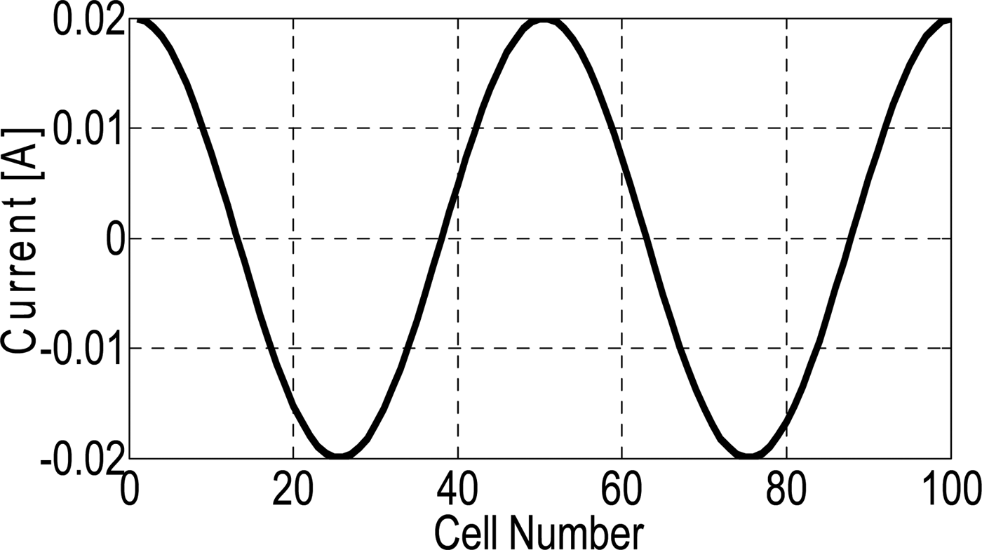
Knowing the values of Г and S, we can apply the iterative process (3) to calculate the current on each cell of the periodic network. Fig. 5 shows the variation of the current along a TL composed of 100 RH cells.
Variation of the current along the TL at 3 GHz and a cell length of λ/50.

It is clear from Fig. 5 that the wavelength, which is, for example the distance between two maxima (50 cells) of the curve of the current variation, is preserved since the cell is λ/50 in length.
III. VARIATION OF THE VOLTAGE ALONG THE TL
After calculating the impedance and current crossing the auxiliary sources at the input of each cell, we can determine the variation of the voltage on the TL.
A) Determination of the input impedance
For a lossless uniform transmission line, the input impedance is given by (9)
 $$Z_{in} = Z_0\displaystyle{{Z_L + jZ_0\tan (\beta l)} \over {Z_0 + jZ_L\tan (\beta l)}},$$
 $$Z_0 = \sqrt {\displaystyle{Z \over Y}} = \sqrt {\displaystyle{{L{\rm ^{\prime}}} \over {C{\rm ^{\prime}}}}} = 50\;\Omega, $$
where Z 0 is the characteristic impedance of the TL, Z L is the load impedance, β is the constant of propagation, and l is the length of the TL.
If the impedance of the load is different from the real characteristic impedance, which is the case of the periodic LC structures where the impedance can only be measured at regular intervals, we obtain a discrete characteristic impedance, which depends on the frequency. Therefore, the impedance of load is different from the characteristic complex impedance of the TL.
The input impedance can be rewritten using the following equation (11):
 $$Z_{in} = Z_B\displaystyle{{Z_L + jZ_B\tan (\beta l)} \over {Z_B + jZ_L\tan (\beta l)}},$$
where Z B is the Bloch impedance given by [Reference Pozar18] (12)
 $$Z_B = \displaystyle{{A - D \pm \sqrt {{(A + D)}^2 - 4}} \over {2C}}.$$
Z in can be rewritten as (13)
 $$Z_{in} = Z_B \displaystyle{{1 + \Gamma_L{e}^{- 2j \beta M \;dz}} \over {1 - \Gamma_L{e}^{- 2j \beta M\;dz}}},$$
where Г L is the reflection coefficient at the load, dz is the length of a unit cell, and M is the number of cell between the load and the plane where the input impedance is measured.
The impedance at the input of the nth cell in the TL is given by (14)
 $$Z_{in \;(n)} = Z_B\displaystyle{{1 + \Gamma _L{e}^{-2j\beta (M - n + 1)dz}} \over {1 - \Gamma _L{e}^{ - 2j\beta (M - n + 1)dz}}}.$$
B) Determination of the current
The vector of the currents at the inputs of cells is known. These currents crossing the auxiliary sources are calculated after the convergence of the iterative process (3) by the following relation (15).
 $$I_n = \displaystyle{1 \over {\sqrt {Z_0}}} (A_n - B_n),$$
where n = 1, 2, 3, …. N is the index of the cell in the TL
C) Determination of the voltage
Using equations (14) and (15), we can calculate the voltages at the inputs of cells (voltage vector) as follows (16):
 $$\left({\matrix{{v_{1}} \cr {v_{2}} \cr \vdots \cr {v_n} \cr}} \right) = \left( {\matrix{ {Z_{in\;1} } & 0 & 0 & \ldots & 0 \cr 0 & {Z_{in\;2}} & 0 & \ldots & 0 \cr \vdots & \vdots & \vdots & \ldots & \vdots \cr 0 & 0 & {} & \ldots & {Z_{in\;(n)}} \cr}} \right)\left({\matrix{ {i_1} \cr {i_2} \cr \vdots \cr {i_n}\cr}}\right). $$
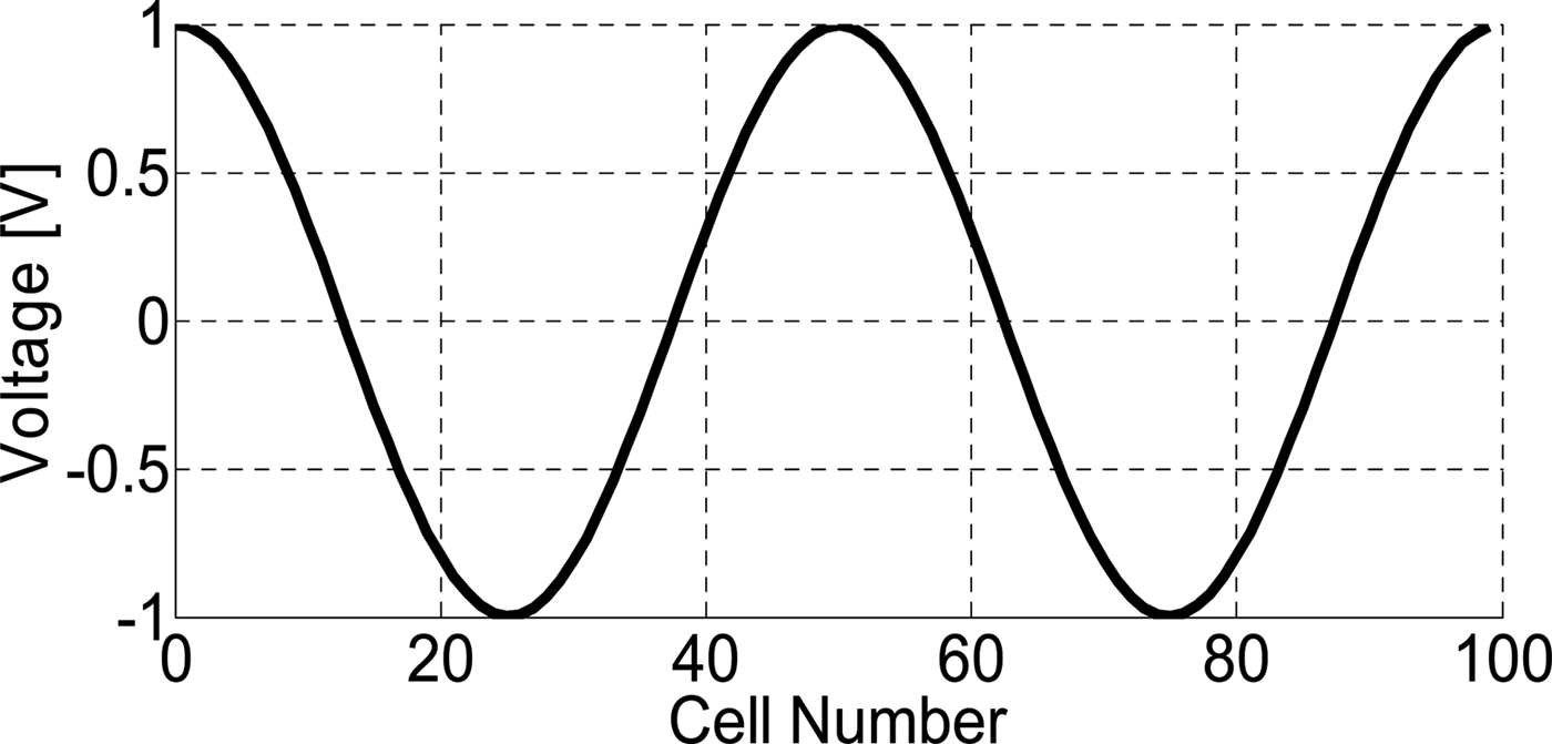
Figure 6 shows the variation of voltage along the transmission line composed of 100 cells.
Variation of the voltage along the TL at 3 GHz and a cell length of λ/50.

We obtain the same variation of the voltage as that of the current. Meanwhile, there is no dephasing between these two curves although our TL is a succession of the reactive elements L and C, which justifies the good choice of the cell length necessary to have a discrete characteristic impedance (Bloch impedance)compared with the TL real characteristic impedance of 50 Ω.
As to the reflection coefficient, it can be calculated using one of the following two equations (17) and (18):
 $$\Gamma _{in} = \displaystyle{{Z_{in} - Z_0} \over {Z_{in} + Z_0}},$$
 $$S_{11} = \displaystyle{{A + (B/Z_0) - CZ_0 - D} \over {A + (B/Z_0) + CZ_0 + D}},$$
where A, B, C, and D are the elements of the ABCD transfer matrix.
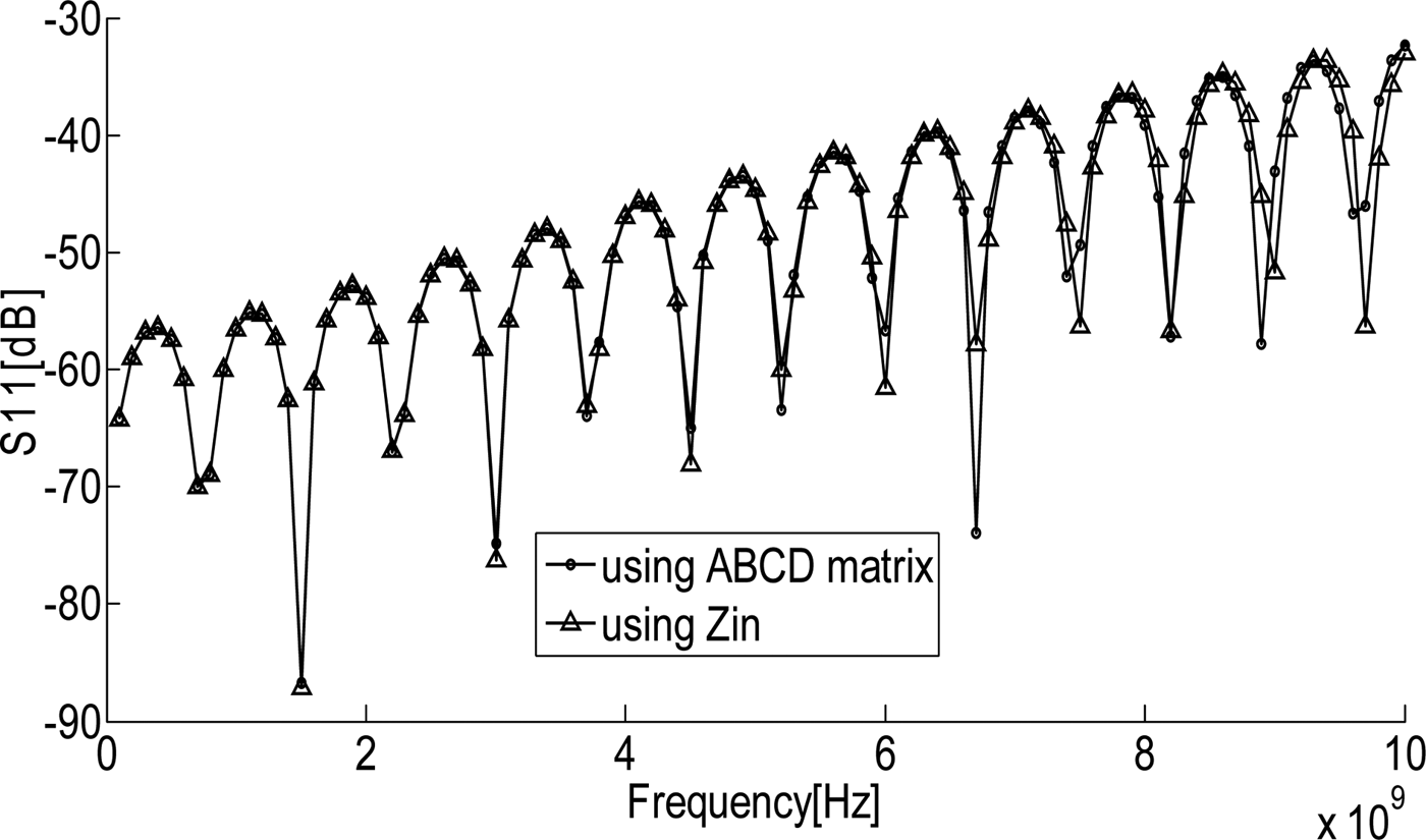
Fig. 7 shows the variation of the reflection coefficient in the band [0–10 GHz] for a TL composed of 100 RH and symmetric unit cells using Z in (17) and the ABCD transfer matrix method (18).The length of a unit cell is λ/50 at 3 GHz.
Variation of the reflection coefficient using Z in and ABCD transfer matrix method.

Observing the periodicity of the reflection coefficient, we notice a small shift between the two curves towards the high frequency, which is due to an increase in the cell length in front of the wavelength. But, when choosing a frequency band of work, the length of the cell should be much smaller than the wavelength at the upper frequency.
As for the periodicity of the reflection coefficient, it has an unknown behavior compared with the non-periodic structures.
The characteristic impedance of a lossless microstrip line is purely real. However, for the transmission lines made up of a succession of LC unit cells, the characteristic impedance can be measured only at regular intervals. It is a complex quantity which depends on the frequency [Reference Pozar18] and its real part tends towards the value of the characteristic impedance of an ideal transmission line for a very small unit cell. This new impedance is named Bloch impedance.
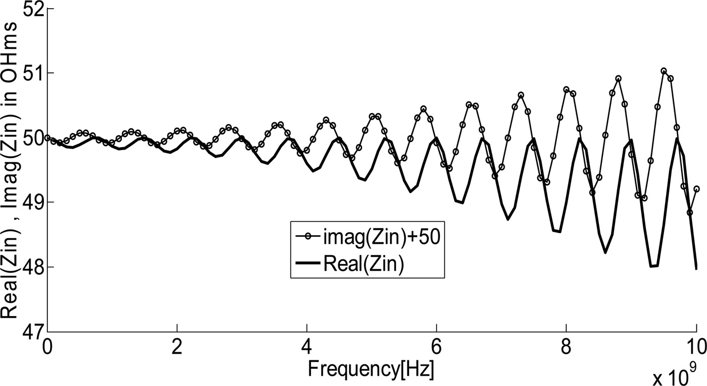
Fig. 8 shows the variation of the input impedance (11) according to the frequency.
Variation of Z in versus the frequency for 100 RH cells.

We summarize the variation of Z in at particular points in Table 1.
Variation of the input impedance at particular points (at transitions).

The variation of the reflection coefficient Г in between the two extremes Min and Max represents its periodicity.
We can clearly reason out the periodicity of Z in . From the expression of the input impedance in (11), we can assume that Z in is periodic and depends on the frequency and the number of cells, which composed the TL. This periodicity at a given frequency can describe several periodicities at different frequencies.
 $$Z_{in}(z + n\;dz) = Z_{in}(z)\;{\rm at}\;{\rm a}\;{\rm frequency}\;f.$$
Let us take θ as the electric length of a unit cell.
 $$\theta = \displaystyle{{2\pi \;dz} \over \lambda} \Leftrightarrow n\theta = \displaystyle{{2\pi n\;dz} \over \lambda} = \displaystyle{{2\pi \;dz} \over c}n \times f.$$
Let us suppose a periodicity of n 1 cells at the frequency f 1.
 $$\eqalign{\theta = \displaystyle{{2\pi \;dz} \over {\lambda _1}} \Leftrightarrow n_1\theta = \displaystyle{{2\pi n_1\;dz} \over {\lambda _1}} = & \displaystyle{{2\pi \;dz} \over c}n_1 \times f_1 \cr \quad \quad \quad = & \displaystyle{{2\pi \;dz} \over c}\displaystyle{{n_1} \over n}n \times f_1,} $$
where dz and c are the length of a unit cell and the celerity of the light, respectively.
A periodicity of n 1 cells at a frequency f 1 is equivalent to a periodicity of n 1/n cells at a frequency n × f 1, as expressed in (21). So, the response to a band of frequencies is a summation of the periodic functions. The sum of the periodic signals at multiple frequencies gives a periodic signal. Hence, a spatial discretization of the transmission line at a given frequency, i.e. many cells per wavelength at a given frequency, contributes to a spectral periodization.
IV. DETERMINATION OF THE LENGTH OF A UNIT CELL
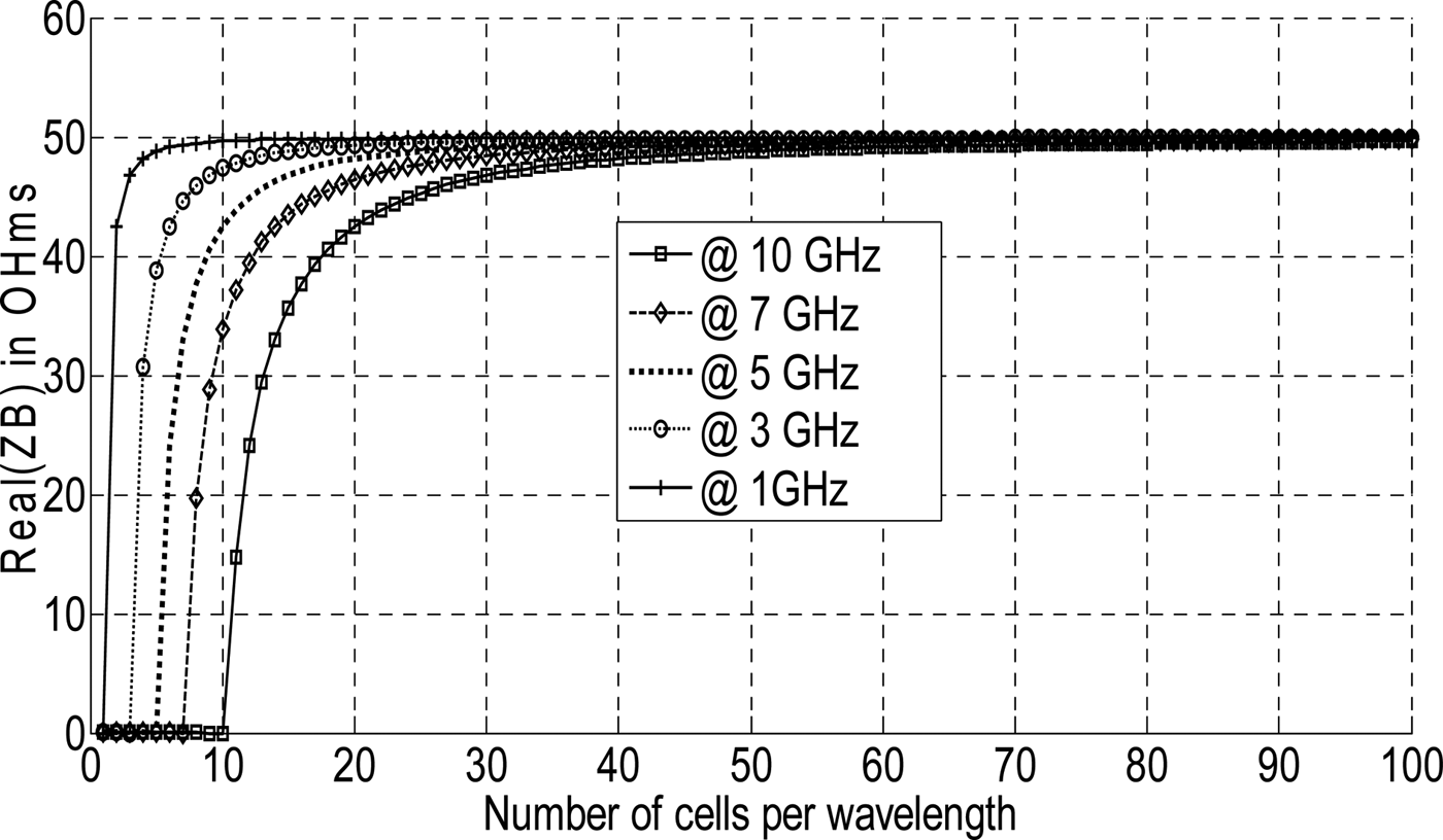
We can obtain a real or almost real behavior of a periodic transmission line if the rate of the space discretization is high. To describe this behavior, it is necessary that the length of the basic unit cell be much smaller than the wavelength. An effective tool to determine this length is to use the Bloch impedance whose real part depends on the length of the cell. Its imaginary part is zero or negligible according to whether the cell is symmetrical or asymmetrical. So, the variation of the Bloch impedance is traced according to the length of a cell at different frequencies in the band [0–10 GHz], as shown in Fig. 9. It is clear that the real part of the Bloch impedance largely approaches to the characteristic impedance of the transmission line of 50 Ω when the length of a unit cell is inferior to λ/50 at the upper frequency of 10 GHz.
Variation of the real (Z B) according to the number of cell per wave length at the corresponding frequency.

The length of a unit cell can be determined with the WCIP method by tracing the variation of the current at an intermediate frequency and for different cell lengths. When the current remains constant in each cell, this indicates the adequate length of the cell to have an almost real behavior of the TL.
V. THE STUDY OF A CRLH CIRCUIT
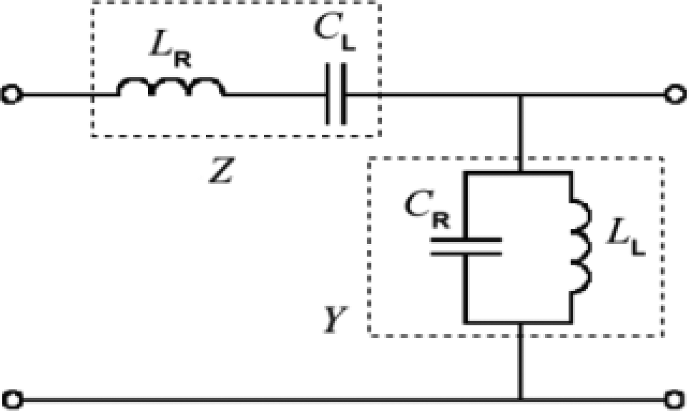
Artificial metamaterials with negative permittivity and permeability can be realized by using a network of CRLH unit cells, as shown in Fig. 10.
A CRLH unit cell.

Z and Y are the per-unit length impedance and per-unit length admittance, respectively. For the CRLH TL, Z and Y are given by (22)
 $$\eqalign{Z = & j\left( {\omega L_R - \displaystyle{1 \over {\omega C_L}}} \right), \cr Y = & j\left( {\omega C_R - \displaystyle{1 \over {\omega L_L}}} \right).} $$
The propagation constant γ of a TL is a function of frequency is given by (23)
 $$\gamma = \alpha + j\beta = \sqrt {Z\,Y}, $$
 $$\alpha = real\,(\,\gamma \,),\quad \beta = imag\,(\,\gamma \,),$$
α and β are respectively the attenuation and propagation constant. We can rewrite β as [Reference Lai, Caloz and Itoh3], (25)
 $$\beta (\omega ) = s(\omega )\sqrt {\omega ^2L_RC_R + \displaystyle{1 \over {\omega ^2L_LC_L}} - \left( {\displaystyle{{L_R} \over {L_L}} + \displaystyle{{C_R} \over {C_L}}} \right)}, $$
where
 $$s(\omega ) = \left\{ {\matrix{ { - 1\;{\rm if}\;\omega \lt \omega _{_1} = \min \left( {\displaystyle{1 \over {\sqrt {L_RC_L}}}, \displaystyle{1 \over {\sqrt {L_LC_R}}}} \right)} \cr { + 1\;{\rm if}\;\omega \gt \omega _2 = \max \left( {\displaystyle{1 \over {\sqrt {L_RC_L}}}, \displaystyle{1 \over {\sqrt {L_LC_R}}}} \right)} \cr}} \right..$$
The CRLH circuit can be treated following two cases.
A) Balanced case
In this case, the resonant frequency of the serial branch (Z) is equal to the resonant frequency of the shunt branch (Y), such that (27).
 $$\,L_RC_L = L_LC_R \Leftrightarrow \displaystyle{1 \over {\sqrt {L_RC_L}}} = \displaystyle{1 \over {\sqrt {L_LC_R}}}. $$
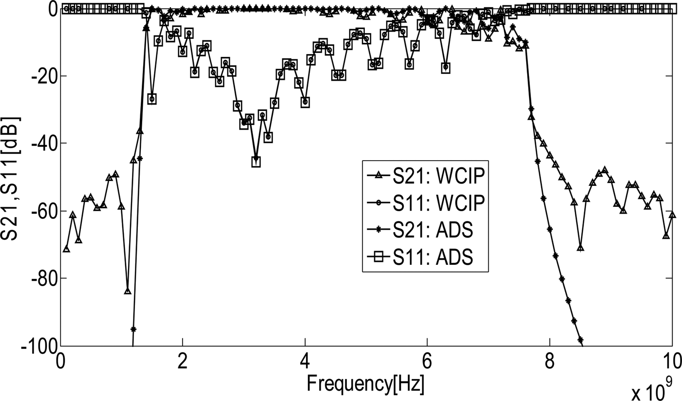
The results of simulation using WCIP method and ADS simulator software for 10 CRLH symmetric and balanced TL unit cells are shown in Fig. 11. In the balanced case, a unit cell is calculated for C R = C L = 1.0 pF and L R = L L = 2.5 nH.
Variation of S 11, S 21 using WCIP and ADS simulators.

The variation of the parameters S shows the behavior of the bandpass filter (CRLH), which is the combination of the two behaviors, namely high pass filter (LH) and low pass filter (RH). There is a good agreement between the simulation results using the WCIP method and ADS simulator software.
B) Unbalanced case
The unbalanced case accounts for the dual process of the balanced case, such that (28)
 $$\,\omega \, \in \,(\omega _1,\;\omega _2) \Rightarrow \beta = 0.$$
For β = 0and α ≠ 0. Consequently, there is no propagation permitted between the resonant frequencies in the bands w 1 and w 2. Figure12 shows the bandgap (stop band) between the two resonant frequencies of 3.2 and 6.4 GHz.
Variations of S 11 and S 21 using WCIP method and ADS simulator.

The simulation is performed for C R = 0.25 pF, C L = 1.0 pF, and L R = L L = 2.5 nH.
There are small differences in the form of small undulations between the simulations made by the ADS and WCIP. Because they do not use the same technique. In fact, the ADS simulator is based on the transfer matrix technique following a continuous model with continuous signals. However, the WCIP method uses the FFT technique following a discrete model with sampled signals.
Application of the CRLH TL as a resonator
A CRLH TL can function as a resonator with the benefit of the frequency of transition from the LH band to the RH band for f 0 = f se = f sh . At this transition frequency, the phase constant is equal to zero (β = 0).
For an open-ended or short-ended TL, the resonances appear with electric lengths, such that
 $$\beta l = m\pi \quad {\rm with}\;m = 0,\,\; \pm 1,\;\,\, \pm 2,\; \ldots, $$
where m is the index of the resonant mode. If m = 0, the resonator becomes a resonator of order zero or exhibits a zeroth resonance mode which is a specific application of CRLH TL. An important property of this kind of resonator is that its frequency of resonance is independent of the length of the TL, which allows the manufacturing of very small resonators.
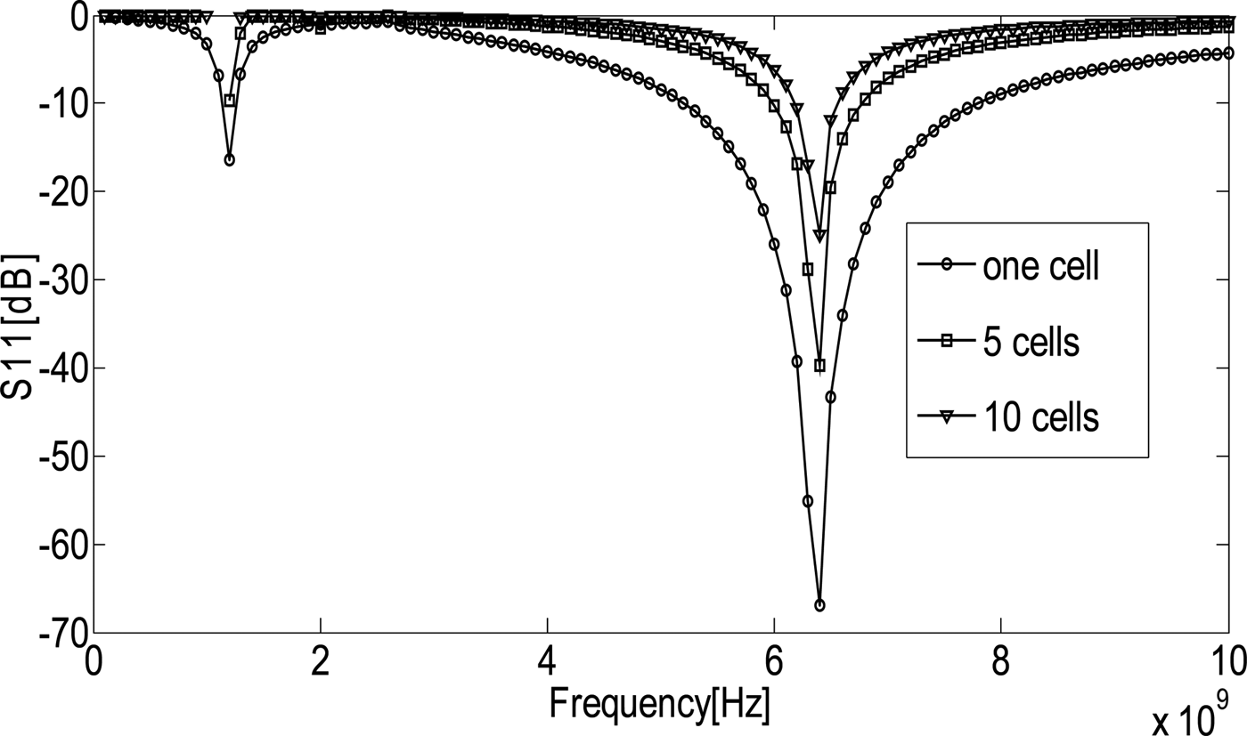
Fig. 13 shows that the resonance where m = 0, C R = C L = 0.25 pF and L R = L L = 2.5 nH is independent of the number of cells. The resonance at the frequency of 6.4 GHz can be calculated using the following equation (30):
 $$f_0 = \displaystyle{1 \over {2\pi \sqrt {L_RC_L}}} = \displaystyle{1 \over {2\pi \sqrt {L_LC_R}}}. $$
Variation of S 11 of zero-order resonator for different number of cells using the WCIP method.

VI. CONCLUSION
This paper proves the ability of the new approach to the WCIP method to study the CRLH circuit, which is the basis of metamaterials. Metamaterials have many applications in microwave and optical domains such as filters, resonators, couplers, antennas, and lenses. The design of many of these applications in a bi-dimensional configuration, which is the main configuration used in the old WCIP method, will be interesting.
 Taieb Elbellili received the Master degrees in Electronic systems from the Faculté des sciences de Tunis in 2006. Since 2015, he is working toward his Ph.D. His research interests include computational electromagnetic methods, almost periodic circuits, metasurfaces, and metamaterials
 Mohamed Karim Azizi was born in Tunis, Tunisia, on December 26, 1979, he received the M.Sc. degree on Telecommunications from SupCom in 2008. He received his Ph.D. degree in Electronics from the Faculty of Sciences of Tunis, Tunisia 2013. He is currently an associated Professor in the department of computer Sciences in The Higher Institute of Multimedia Arts of Mannouba, ISAMM, Tunisia, his research interest at present include metamaterials, metasurfaces, and graphene antennas.
 Lassaad Latrach received the Master degree in Electronic Systems from The Faculte des Sciences de Tunis in 2006. He received his Ph.D. degree in Electronics from the Faculty of Sciences of Tunis, Tunisia in 2010. He is an Associated Professor in EMSI Mannouba Tunisia. His research interests include computational electromagnetic methods, passive and active circuits, and antennas.
 Hichem Trabelsi was born in Tunisia, in 1962. He received the Ph.D. degree in Electronics from the University of Pierre & Marie Curie, Paris VI, France in 1991. He joined the Department of Physics at the Faculty of Sciences, Tunis in 1992, where he is currently working on microwave active and passive filters and electromagnetic theory for solving field problems in microwave circuits
 Ali Gharsallah received the Radio Frequency Engineering degree from the Higher School of Telecommunication of Tunis, Tunis, Tunisia, in 1986, and the Doctor of Philosophy degree from the Engineering School of Tunis, Tunis, Tunisia, in 1994. Since 1991, he has been with the Faculté des Sciences de Tunis, Department of Physics University Tunis Manar Faculty of Sciences of Tunis, Tunis, Tunisia. He is also a full professor of Electrical Engineering and director of Engineering with the Higher Ministry Education of Tunisia, Tunis, Tunisia. He has authored or coauthored approximately 70 papers published in scientific journals and 120 conference papers. He has also supervised over 20 theses and 50 masters. His current research interests include smart antennas, array signal processing, multilayered structures, and microwave integrated circuits.
 Henri Baudrand (SM'90-F'04-LF'14) received the Ph.D. degree in microwaves from the Institut National Polytechnique, Toulouse, France, in 1966. He is a Professor Emeritus with the Ecole Supérieure d'Electronique Electrotechnique Informatique, ENSEEIHT, National Polytechnic Institute of Toulouse, Toulouse, France. He has authored and coauthored six books: Introduction au calcul des éléments de circuits microondes, optimisation des circuits non linéaires, calcul des circuits microondes par les schémas équivalents (CEPADUES Editions Toulouse), New Trends and Concept in Microwave Theory and Technics, Adaptation de la méthode WCIP aux circuits SIW et SINRD: WCIP: Wave Concept Iterative Process, and Modélisation Globale des Circuits Electroniques Hautes Fréquences. He cosigned over 110 publications in journals, four chapters in scientific books, and 250 communications in international conferences. He is a Fellow Member of “Electromagnetism Academy” and Senior Member of IEE Society. He was President of URSI France Commission B for 6 years (1993–1999), the IEEE-MTT-ED French chapter (1996–1998), and the International Comity of O.H.D. (Hertzian Optics and Dielectrics) between 2000 and 2004. He was the recipient of Officier des Palmes académiques and Doctor Honoris causa of lasi University (1996).