Introduction
Modern wireless communication systems rely heavily on good antenna designs to function well. Well-optimized antennas enable increased data speeds, enhanced gain, and decreased alignment sensitivity. Circular polarization (CP) multi-port designs are especially beneficial since they increase data throughput using diversity methods without requiring more transmission power [Reference Sharawi1]. Additionally, CP reduces signal fading and guarantees orientation-independent communication [Reference Sharma, Gupta, Das and Gangwar2]. Ceramic radiators are becoming more and more popular than traditional printed radiators because of their lower metallic losses, which allow for larger gain with fewer losses [Reference Petosa3]. Simultaneously, the use of machine learning (ML) techniques is revolutionizing antenna creation by facilitating the quick and precise optimization of design parameters via the study of extensive performance data [Reference Misilmani, Naous and Khatib4].
Multi-terminal ceramic radiators have been the subject of several investigations. By using polarization diversity in the 5.33–5.79 GHz range, Das et al. [Reference Das, Sharma and Gangwar5], for example, suggested a two-terminal ceramic radiator that is driven by a modified round slot and achieves isolation greater than −25 dB. Varshney et al. [Reference Varshney, Singh, Pandey and Yaduvanshi6] developed a dual-terminal ceramic antenna that can generate rotational waves; it operates from 6.86 to 7.19 GHz and has a 3-dB ARBW across 6.98–7.11 GHz. Hu et al. [Reference Hu, Pan and Yang7] developed a 2-port ceramic antenna that operates from 2.38 to 2.57 GHz and accommodates cyclic radio waves between 2.41 and 2.53 GHz.A polarization converter allowed circular propagation between 5.53 and 5.99 GHz in a two-terminal ceramic antenna built by Abhay et al. [Reference Yadav, Verma, Penmatsa and Sharma8] to be used in the 5.27–6.07 GHz region. Similarly, a metasurface (MS)-loaded two-terminal ceramic radiator spanning 5.17–5.45 GHz with a circular rotation inside 5.33–5.42 GHz was suggested by Gupta et al. [Reference Gupta, Alam, Yadav and Sharma9]. A two-terminal slot-fed ceramic radiator that runs in the 4.13–4.59 GHz range and achieves circular rotation of the field from 4.17 to 4.45 GHz was suggested by Tripathi et al. [Reference Tripathi, Sharma and Kumar10]. To successfully lower the RCS within the operational range, an MS layer was included. Anitha et al. [Reference Anitha, Singh, Dwivedi and Narayanaswamy11] planned a printed radiator in the mm-wave spectrum loaded with an MS (acts as a polarization convertor). It functions from 37.1 to 39.2 GHz with CP fields 38.2–38.6 GHz. Vankadhari et al. [Reference Vankadhari, Dwivedi, Singh and Narayanaswamy12] suggested filtering radiator in the terahertz band, with the help of Silicon ceramic. It functions from 2.49 to 3.29 THz with circular fields within 2.59–2.89 THz.
The use of ML methods to radiator development and evaluation in the microwave spectrum has been the subject of various studies. These methods have shown promise in enhancing design as well as performance projection. For instance, Zheng et al. [Reference Zheng, Chen and Huang13] used an AI model to precisely forecast the |S11| factor of a patch antenna so as to improve it. Sharma et al. [Reference Sharma, Zhang and Xin14] analyzed the efficacy of many ML techniques, such as Lasso regression, K-Nearest Neighbors (KNN), and Artificial Neural Network (ANN), to assess the performance of a T-formed printed radiator. Similarly, to improve the efficacy of a Ultra Wide Band (UWB) printed radiator, Ranjan et al. [Reference Ranjan, Maurya, Gupta, Yadav and Sharma15] used a variety of ML approaches. Srivastava et al. [Reference Srivastava, Gupta, Dwivedi, Penmatsa, Ranjan and Sharma16] used Knowledge-Based Neural Network (KBNNs) to overcome the drawbacks of traditional ANN models and precisely forecast the ∣ՏS11∣. For an L-formed fed ring dielectric multi-port antenna intended to function with CP in the 2.8–3.05 GHz band, Pandey et al. [Reference Pandey, Singh and Kumar17] also used a variety of ML approaches. Dwivedi et al. [Reference Dwivedi, Singh, Ranjan, Sharma and Singh18] planned a two-terminal MS-loaded printed radiator in the mm-wave spectrum. ML approaches are used to predict the |S11| performance of the designed radiator.
The design and analysis of a two-port dielectric radiator with an MS incorporated is presented in this paper. The intended filtering response is achieved via a microstrip feed that has two unequal stubs. In addition to stimulating CP, the suspended MS enhances port isolation and lowers coupling to less than −25 dB. Additionally, XGBoost and Random Forest (RF) ML models are used to forecast the radiator’s |S11|. Novelty aspect of the planned radiator is as follows:
• Integration of suspended double-negative (DNG) MS with a ceramic antenna to achieve simultaneous circular waves, gain improvement, and filtering.
• Data-driven design validation using ML (RF, XGBoost) for predicting ∣S11∣, which is still rare in antenna design literature.
The article is organized into five parts for ease of reading: (a) antenna layout; (b) performance analysis; (c) prediction based on ML; (d) experiment confirmation; and (e) conclusion.
Antenna layout
The design of the suggested two-port dielectric radiator, shown in Fig. 1, is described in this section. The resonator of alumina (Ɛr = 9.8) is stimulated via a rounded slot that receives its input from a microstrip line that has two uneven stubs. The substrate of FR-4 (Ɛr = 4.4, HS = 1.6 mm) hosts the feed structure, with the ground plane on its top surface and the printed line on the bottom. To enhance performance, an MS, which is likewise made on FR-4, is hung above the radiator. Table 1 lists all of the important antenna parameters’ optimal dimensions.
Design of the intended two-terminal antenna. (a) Feeding configuration. (b) Dielectric radiator. (c) MS layout. (d) Adjacent radiator sight.

Optimum measurements of the planned two-terminal antenna’s various components

Antenna investigation
This section provides a thorough HFSS analysis of the suggested antenna. First, a single-port radiator is used in the investigation. Figure 2 shows the ∣ՏS11∣ response in the following three situations: (a) printed-line fed slot with no ceramic, (b) printed-line fed slot with a ceramic, and (c) printed line with dual-stub fed slot stimulating ceramic. Important findings from Fig. 2 include: (i) the ceramic is the primary source of the functional band, and (ii) the impedance BW is enhanced by the inclusion of stubs. Figure 3 presents the E-field distribution on the ceramic at resonance. The field pattern is similar to the basic HEM11δ hybrid mode [Reference Kajfez, Glisson and James19], which the slot excitation mechanism also supports. The following empirical equation may be used to estimate the mode [Reference Sharma, Das and Gangwar20]:
 \begin{equation}{f_r} = \frac{{6.324c}}{{2\pi D\sqrt {\varepsilon + 2} }}\left\{ {0.27 + 0.36\left( {\frac{D}{{4H}}} \right) + 0.02{{\left( {\frac{D}{{4H}}} \right)}^2}} \right\}\end{equation}
Curve of |S11| showing different changes to the solo terminal radiator’s feed.

E-field patterns at 2.55 GHz on ceramic. (a) Upper sight. (b) Side sight.

The dielectric rod’s height and diameter are indicated by “D” and “H” in this equation, and its relative permittivity is shown by εr. In total, 2.43 GHz is the computed resonance derived from (1), and it closely resembles the resonance shown in the simulation findings.
The gain fluctuation under three distinct situations is shown in Fig. 4. A dielectric rod is connected to a printed line-fed slot in (a), a single stub-fed slot-fed slot-coupled to the dielectric rod in (b), and two uneven stub-fed slots-coupled to the dielectric rod in (c). As can be seen from Fig. 4, the gain in instance (a) exhibits a smooth rise and fall across the band. The addition of a single elongated stub, however, drastically lowers the gain in example (b), bringing it below −15 dB at 2.25 GHz. When two unequal stubs are added in scenario (c), the gain is further suppressed to less than −20 dB at 3.25 GHz. The creation of radiation nulls at these frequencies is responsible for this decrease [Reference Dwivedi, Singh, Ranjan, Sharma and Singh18]. As a result, the suggested radiator has bandpass filtering properties.
Curve of gain with several changes in the feed line.

By connecting the terminals in parallel, the single-terminal radiator may be expanded into a two-terminal setup. Figure 5 shows the relevant S-parameters. While the coupling in the two-terminal design is kept below −15 dB, it is evident that the |S11| response is almost the same in the solo and two-terminal situations. A unit cell is created and organized regularly to form an MS in order to further increase isolation. Figure 6 displays the unit cell’s effective permittivity and permeability. Within the operational band, the permittivity is positive and the permeability is negative, indicating that the unit cell functions as a DNG MS. After that, this MS is hung above the radiator with two terminals. Figure 7, which displays the S-parameters with and without the MS, illustrates the effect of MS loading. Two important findings are noted: (a) the MS has little effect on the |S11| characteristics, and (b) the coupling between is also not much affected by the placement of MS.
Curve of S-parameter with a solo/two-terminal antenna.

Curve of permittivity/permeability for the suggested unit cell.

Curve of S-parameter presence and absence of MS.

The axial ratio (AR) properties with and without the MS are shown in Fig. 8. It is clear that adding the MS ensures CP by bringing the AR over the working range down to less than 3 dB. Because it divides the linear electric field into two perpendicular components of equal amplitude with a 90° phase difference, a necessary prerequisite for CP radiation, the proposed unit cell is fundamental to the generation of CP waves [Reference Balanis21]. The broadside gain performance with and without the MS is shown in Fig. 9. The findings demonstrate that adding the MS raises the gain by around 3 dB, reaching an operating band maximum of 8.9 dBi. This improvement results from the DNG characteristic of the MS, which raises the directivity of the radiator [Reference Samantaray and Bhattacharyya22].
Curve of AR with and w/o MS.

Curve of gain with and w/o MS.

|S11| prediction using ML methods
This section’s goal is to demonstrate how ML methods may be used to estimate the |S11| properties of the suggested radiator. For this, two popular algorithms are used: XGBoost and RF. During training, RF, an ensemble-based ML technique, builds a lot of decision trees. Averaging (for regression tasks) or majority voting (for classification tasks) is used to combine the separate outputs from each tree to get the final prediction. A more sophisticated ensemble technique that makes use of the boosting idea is XGBoost. This method involves building many decision trees one after the other, with each new tree concentrating on fixing the mistakes (residuals) caused by the ones before it. When compared to many other ML algorithms, XGBoost is renowned for providing higher accuracy and quicker convergence because of its effective optimization method, regularization techniques, and scalability.
After the radiator was designed in HFSS, its geometric parameters were systematically changed to provide the necessary datasets. LF1 (0.3–4.25 mm), LF2 (1.5–8.5 mm), DS (6.5–13.5 mm), D (15.0–25.0 mm), H (6.0–14.0 mm), HM (12.0–19.0 mm), LF (8.5–13.5 mm), and WF (1.0–4.0 mm) were the arrays, in which parameters were changed using increments of 0.25 mm. In total, 101 evenly spaced sampling sites were used to conduct a frequency sweep throughout the 2.0–3.5 GHz range, yielding 124,667 data samples in total. Thirty percent of them were set aside for testing, and seventy percent were utilized to train the ML models.
The performance of the trained ML models is assessed using the test dataset. The findings are compiled in Table 2 for ∣ՏS11∣ forecasts. With the greatest R2 score and the lowest mean error in both scenarios, it is clear from these data that XGBoost performs better than RF.
Evaluation of design in light of |S11| performance standards

Figure 10 shows the predicted vs real ∣ՏS11| for the RF and XGBoost models. The ideal regression result, when predicted and actual values exactly correspond, is shown by the line Y = X. When a greater density of data points closely matches this line, the model performs better. Out of the two models, XGBoost exhibits the best prediction accuracy with the closest alignment to the ideal line. The anticipated findings show growing discrepancies from the actual data as the values become increasingly negative.
Comparison between expected and actual results ∣Տ 11∣. (a) XGBoost. (b) RF model.

Experimental verification
In this part, ML predictions and the improved simulation results are verified against real-world observations. The suggested radiator’s manufactured prototype, created by a chemical etching method, is shown in Fig. 11. The ceramic rod is adhered to the substrate. The comparison of measured, simulated, and ML-predicted S-parameters is shown in Fig. 12. There is good agreement among the tested, simulated, and predicted outcomes. There is a slight shift seen between the tested and simulated ones, which is due to the use of glue to fix the ceramic, as well as due to the SMA connector. The antenna maintains a coupling level below −20 dB and functions well in a 2.33–3.35 GHz span.
Images of the radiator archetype. (a) Feed assembly. (b) MS model. (c) Isometric sight.

Tested/Simulated/Projected S-parameter curve.

The suggested radiator’s tested and simulated AR is shown in Fig. 13. The dual-pattern measuring approach was used to assess the AR within an anechoic room [Reference Stutzman and Thiele23]. The simulated and tested findings show a high degree of consistency. CP is maintained by the antenna across the 2.49–3.25 GHz span.
Tested/Simulated AR curve.

The LHCP/RHCP for terminals 1 and 2 in the XZ-plane at 2.7 GHz are shown in Fig. 14. There is a strong correlation between the simulated and measured polar plots. The graphs also support LHCP, and the broadside pattern confirms the excitation of the basic hybrid mode.
Polar graph of LHCP/RHCP at 2.7 GHz. (a) Port-1. (b) Port-2.

The suggested radiator’s tested and simulated gain are shown in Fig. 15. The two-antenna method was used to measure the gain in an anechoic room [Reference Stutzman and Thiele23]. Tested and simulated results show a significant connection. Within the functioning band, the radiator’s gain is steady at about 8.9 dBi; however, outside of this range, it falls below −15 dB. The suggested design is contrasted with other documented two-terminal ceramic antennas in Table 3. The findings verify that the suggested radiator performs better overall in terms of gain, polarization, isolation, and bandwidth.
Tested/Simulated gain curve.

Performance assessment of the proposed radiator against existing MIMO designs

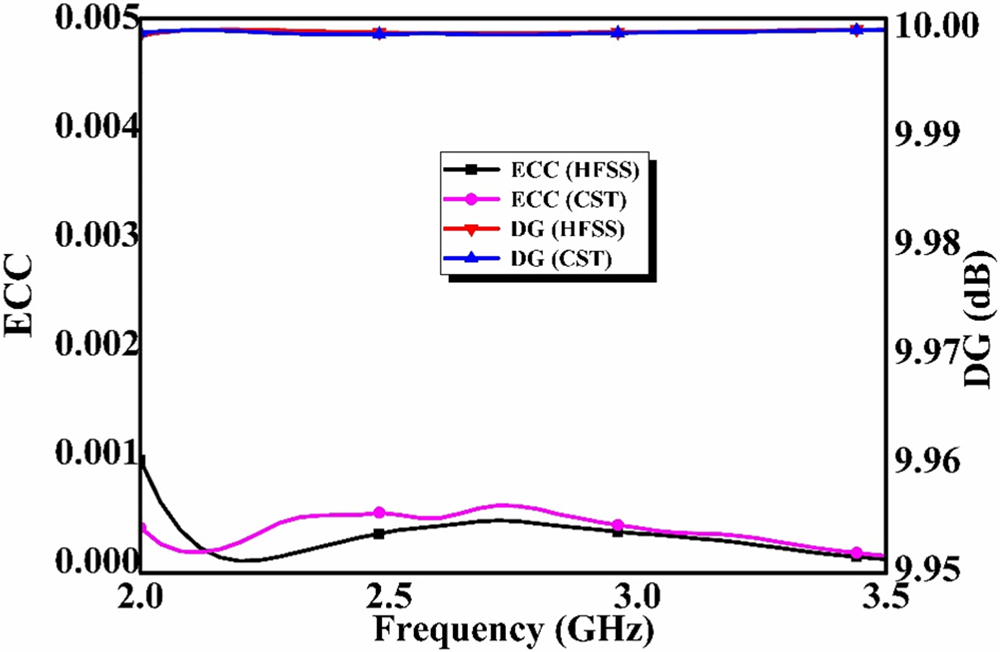
Figure 16 displays Diversity Gain (DG) and Envelop Corellation Coefficient (ECC) that were computed for the suggested radiator. ECC displays the correlation among the radiator’s ports, whereas DG shows how well the antenna performs under fading channel circumstances. The DG should be nearly 10 dB and the ECC should be below 0.2 across the operational range for an efficient Multi Input Multi Output (MIMO) antenna [Reference Das, Sharma and Gangwar24]. It is clear from Fig. 16 that the developed radiator meets these requirements, indicating that it is appropriate for MIMO applications.
Measured/Simulated ECC/DG graph.

Conclusion
The design and analysis of a two-port dielectric antenna with a suspended MS incorporated have been completed. By adding a filtering feature, the feed structure produces a gain of around 5.5 dBi within the operational range and suppresses it to approximately −15 dBi outside. The suspended MS improves the gain to above 8.5 dBi and permits CP in the 2.49–3.25 GHz span. The |S11| performance is also predicted using ML models. The fundamental hybrid mode is excited, which allows the antenna to function well in the 2.33–3.35 GHz range. Because of these features, the suggested architecture is ideal for 5G communication applications operating at frequencies lower than 6 GHz. Advantages of planned radiator are as follows:
• Feed design provides filtering characteristics
• Suspended MS improves the gain and creates CP waves within the operating regime
• Use of RF and XGBoost to predict ∣S11∣ is a novel contribution, reducing dependence on repetitive full-wave simulations
Limitations of the planned radiator are as follows:
• Precise alignment of the suspended MS and ceramic may introduce fabrication challenges.
• Use of glue for fixing the dielectric rod may affect repeatability and introduce minor uncertainties in measurements.
Funding statement
This research received no specific grant from any funding agency, commercial or not-for-profit sectors.
Competing interests
The authors report no conflict of interest.

Abhishek Kumar received the B.E. and M.Tech. degrees in Electronics and Communication Engineering from Rajiv Gandhi Technical University (Govt.), India. He has more than five years of industry experience and is currently pursuing the Ph.D. degree in Electronics and Communication Engineering from Rabindranath Tagore University (RNTU), Bhopal, India. His research interests include electronic systems, communication technologies, embedded systems, VLSI design, and innovation in engineering design.

Jitendra Ahir received the B.Tech. degree in Electronics and Communication Engineering from Scope College of Engineering (RGPV University) Bhopal, the M.Tech. degree in Digital Communication from Scope College of Engineering (RGPV University) Bhopal, and the Ph.D. degree from Rabindranath Tagore University, Raisen, in the area of Microstrip Patch Antenna. He has more than 13 years of teaching and administrative experience.

Sanjeev Kumar Gupta received the B.E. degree in Electronics and Communication, the M.Tech. degree in Digital Communication, and the Ph.D. degree in Electronics and Communication Engineering from the University Institute of Technology (UIT), Barkatullah University Bhopal. In May 2000, he joined, AISECT group of Institutions. He has guided eight M.Tech. and thirteen Ph.D. research scholars. To his credit, four patents have been published. He has delivered a number of invited talks on many national platforms of repute. He has worked as an expert member in various committees of different institutions. He is also co-coordinating at Rabindranath Tagore University (formerly known as AISECT University) Bhopal. His current research interests include wireless communications, wireless sensor networks, control systems, microprocessors, and microcontrollers. He is a Fellow of the Institution of Electronics and Telecommunication Engineers (IETE). He organized various workshops, conferences, and faculty development programs. He has published 62 papers in National and International journals during his Ph.D. program at the university.