1 Introduction
The incompressible flow past a circular cylinder of diameter
 $D$
can present different patterns, depending on the Reynolds number
 $Re$
(
 $Re=\unicode[STIX]{x1D70C}UD/\unicode[STIX]{x1D707}$
, where
 $\unicode[STIX]{x1D70C}$
is the fluid density,
 $U$
is the free-stream speed and
 $\unicode[STIX]{x1D707}$
the fluid dynamic viscosity). If the cylinder is fixed, the flow is steady for low Reynolds number. The first instability occurs at Reynolds number
 $Re_{c_{0}}\cong 47$
(Jackson Reference Jackson1987; Dusĕk, Le Gal & Fraunie Reference Dusĕk, Le Gal and Fraunie1994), when the von Kármán wake develops and the flow becomes time-periodic. When the cylinder is free to oscillate, past studies have shown that the first instability can happen for lower Reynolds numbers. Mittal & Singh (Reference Mittal and Singh2005) investigated the flow past a spring-mounted cylinder, allowed to oscillate in both the transverse and in-line directions, for
 $Re<Re_{c_{0}}$
. They observed vortex shedding and oscillation of the cylinder for some values of reduced velocity
 $V_{r}$
(
 $V_{r}=Uf_{n}/D$
, where
 $f_{n}$
is the natural frequency of the structure in vacuum). Lock-in was verified in all these cases.
The occurrence of the first instability for
 $Re<Re_{c_{0}}$
was also investigated using linear stability analysis. Cossu & Morino (Reference Cossu and Morino2000) were the first to apply this tool for the flow around flexibly mounted circular cylinders. They identified an instability at
 $Re=23.5$
for non-dimensional mass ratios (mass of the moving body divided by the mass of displaced fluid)
 $m^{\ast }=7$
and
 $m^{\ast }=70$
with the cylinder free to oscillate in the transverse direction. Besides that, they identified two unstable modes, referred in that work as nearly structural and von Kármán modes. For large mass ratio
 $m^{\ast }$
, the eigenvalue of the nearly structural mode tended to the natural frequency of the structure and the eigenvalues of the von Kármán mode corresponded to the leading eigenvalues of the flow past a fixed cylinder. Later, Meliga & Chomaz (Reference Meliga and Chomaz2011), Zhang et al. (Reference Zhang, Li, Ye and Jiang2015), Navrose (Reference Navrose2016), Kou et al. (Reference Kou, Zhang, Liu and Li2017) and Yao & Jaiman (Reference Yao and Jaiman2017) also showed results that confirmed instability for
 $Re<Re_{c_{0}}$
. Meliga & Chomaz (Reference Meliga and Chomaz2011) introduced a mapping of stable and unstable regions with respect to the parameter
 $m^{\ast }$
for flow past a circular cylinder free to oscillate in both the transverse and in-line directions. Navrose (Reference Navrose2016) introduced a mapping with respect to
 $Re$
and
 $m^{\ast }$
in which decoupled and coupled modes were identified. They verified that the two least stable decoupled modes presented the same characteristics as those shown by Cossu & Morino (Reference Cossu and Morino2000), and renamed them fluid mode (FM) and elastic mode (EM). The two least stable coupled modes were referred to as fluid elastic mode I (FEMI) and fluid elastic mode II (FEMII). These modes did not present a distinction in terms of behaviour – that is, they could not be classified into fluid or elastic modes. In several cases, these modes were identified for
 $m^{\ast }<10$
. Navrose (Reference Navrose2016) also showed that for
 $(Re,m^{\ast })=(40,10)$
the lock-in
 $V_{r}$
range matched the
 $V_{r}$
range for which the EM was unstable. Outside this range the cylinder remained at rest and the fluid was steady.
For the flow around a fixed circular cylinder, the nonlinear character of the primary instability has also been studied (Provansal, Mathis & Boyer Reference Provansal, Mathis and Boyer1987; Sreenivasan, Strykowski & Olinger Reference Sreenivasan, Strykowski, Olinger and Ghia1987), and it is known that it corresponds to a supercritical Hopf bifurcation. This means that the steady flow becomes time-periodic and that the bifurcation does not present hysteresis. However, to the best of the authors’ knowledge, no study has yet assessed the nonlinear character of the primary bifurcation in the flow around a flexibly mounted circular cylinder. This work intends to fill this gap, and check if hysteresis can be observed for Reynolds numbers in the vicinity of the critical Reynolds number
 $Re_{c}$
of the flow past a circular cylinder free to oscillate, thus characterising a subcritical bifurcation. To do that, different configurations by varying parameters and the oscillation direction are evaluated. The reduced velocity
 $V_{r}$
, mass ratio
 $m^{\ast }$
and number of degrees of freedom are all important in the structural response of flexibly mounted cylinders immersed in a fluid flow for higher Reynolds numbers. For this reason, this work intends to verify if they also have any influence on the nonlinear character of the primary bifurcation. The reduced velocity has a very clear importance in the response of the system, as the amplitude of vibration is significant in the lock-in range, and very small elsewhere. Therefore, to identify the primary bifurcation character inside and outside of the lock-in range, different values of reduced velocity are considered. Regarding the number of degrees of freedom, below a certain mass ratio, Jauvtis & Williamson (Reference Jauvtis and Williamson2003) have shown that the system responds differently in the lock-in range if it has one or two degrees of freedom. Finally, it has been well established in earlier work (Govardhan & Willianson (Reference Govardhan and Willianson2000)) that the mass ratio
 $m^{\ast }$
parameter is of utmost importance for the structural response of the system in the lock-in regime at higher Reynolds number. This manuscript also investigates whether the character of the primary bifurcation is changed by employing relatively high and low
 $m^{\ast }$
values. For each combination of parameters, linear stability analysis is applied to find the critical Reynolds
 $Re_{c}$
, and nonlinear analysis is performed to determine the character of the bifurcation.
2 Governing equations
2.1 Nonlinear analysis
Consider a viscous two-dimensional flow around a flexibly mounted circular cylinder free to oscillate in the transverse and in-line directions with boundary conditions correctly satisfied. Applying the non-inertial frame of reference method (Li, Sherwin & Bearman Reference Li, Sherwin and Bearman2002), the nonlinear fluid–structure interaction (FSI) system is described by the following non-dimensional equations:
 $$\begin{eqnarray}\displaystyle & \displaystyle \frac{\unicode[STIX]{x2202}\boldsymbol{u}}{\unicode[STIX]{x2202}t}+\unicode[STIX]{x1D735}\boldsymbol{u}\boldsymbol{\cdot }\boldsymbol{u}-\frac{1}{Re}\unicode[STIX]{x1D6FB}^{2}\boldsymbol{u}+\unicode[STIX]{x1D735}p+\ddot{\boldsymbol{y}}=\mathbf{0}, & \displaystyle\end{eqnarray}$$
 $$\begin{eqnarray}\displaystyle & \displaystyle \unicode[STIX]{x1D735}\boldsymbol{\cdot }\boldsymbol{u}=0, & \displaystyle\end{eqnarray}$$
 $$\begin{eqnarray}\displaystyle & \displaystyle \frac{\unicode[STIX]{x03C0}m^{\ast }}{4}\ddot{\boldsymbol{y}}+\frac{\unicode[STIX]{x03C0}^{2}\unicode[STIX]{x1D701}m^{\ast }}{V_{r}}\dot{\boldsymbol{y}}+\frac{\unicode[STIX]{x03C0}^{3}m^{\ast }}{V_{r}^{2}}\boldsymbol{y}=\boldsymbol{F}(\boldsymbol{u},p). & \displaystyle\end{eqnarray}$$
The vector
 $\boldsymbol{u}(\boldsymbol{x},t)$
represents the velocity field and
 $p(\boldsymbol{x},t)$
is the pressure. The variables
 $\boldsymbol{y}=\boldsymbol{y}(t)$
,
 $\dot{\boldsymbol{y}}=\dot{\boldsymbol{y}}(t)$
and
 $\ddot{\boldsymbol{y}}=\ddot{\boldsymbol{y}}(t)$
are the vectors of displacement, velocity and acceleration of the cylinder, respectively. The coefficient
 $\unicode[STIX]{x1D701}$
is the structural damping and
 $\boldsymbol{F}$
is the instantaneous non-dimensional fluid force acting on the cylinder given by
 $$\begin{eqnarray}\boldsymbol{F}(\boldsymbol{u},p)=\int _{\unicode[STIX]{x2202}\unicode[STIX]{x1D6FA}_{w}}\boldsymbol{n}\boldsymbol{\cdot }\{-p\unicode[STIX]{x1D644}+Re^{-1}(\unicode[STIX]{x1D735}\boldsymbol{u}+(\unicode[STIX]{x1D735}\boldsymbol{u})^{\text{T}})\}\,\text{d}S_{w},\end{eqnarray}$$
where
 $\unicode[STIX]{x2202}\unicode[STIX]{x1D6FA}_{w}$
refers to the cylinder surface.
2.2 Linear stability analysis
To perform the global linear stability analysis, the state vector
 $\boldsymbol{q}=[\boldsymbol{u},p,\boldsymbol{y},\dot{\boldsymbol{y}}]^{\text{T}}$
is written as the sum of the base and perturbation fields (i.e.
 $\boldsymbol{q}=\boldsymbol{Q}+\boldsymbol{q}^{\prime }$
). The base flow
 $\boldsymbol{Q}=[\boldsymbol{U},P]^{\text{T}}$
is the steady flow around a fixed cylinder, governed by Navier–Stokes equations
 $$\begin{eqnarray}\displaystyle \left.\begin{array}{@{}c@{}}\displaystyle \boldsymbol{U}\boldsymbol{\cdot }\unicode[STIX]{x1D735}\boldsymbol{U}-\frac{1}{Re}\unicode[STIX]{x1D6FB}^{2}\boldsymbol{U}+\unicode[STIX]{x1D735}P=0,\\ \displaystyle \unicode[STIX]{x1D735}\boldsymbol{\cdot }\boldsymbol{U}=0.\end{array}\right\} & & \displaystyle\end{eqnarray}$$
We assume that the perturbation is infinitesimal and that the coordinate system is fixed to the cylinder, so the perturbation field
 $\boldsymbol{q}^{\prime }=[\boldsymbol{u}^{\prime },p^{\prime },\boldsymbol{y}^{\prime },\dot{\boldsymbol{y}}^{\prime }]^{\text{T}}$
is governed by the linearised FSI system
 $$\begin{eqnarray}\displaystyle \left.\begin{array}{@{}c@{}}\displaystyle \frac{\unicode[STIX]{x2202}\boldsymbol{u}^{\prime }}{\unicode[STIX]{x2202}t}+\boldsymbol{U}\boldsymbol{\cdot }\unicode[STIX]{x1D735}\boldsymbol{u}^{\prime }+\unicode[STIX]{x1D735}\boldsymbol{U}\boldsymbol{\cdot }\boldsymbol{u}^{\prime }-\frac{1}{Re}\unicode[STIX]{x1D6FB}^{2}\boldsymbol{u}^{\prime }+\unicode[STIX]{x1D735}p^{\prime }+\frac{\text{d}\dot{\boldsymbol{y}}^{\prime }}{\text{d}t}=0,\\ \displaystyle \unicode[STIX]{x1D735}\boldsymbol{\cdot }\boldsymbol{u}^{\prime }=0,\\ \displaystyle \frac{\text{d}\boldsymbol{y}^{\prime }}{\text{d}t}=\dot{\boldsymbol{y}}^{\prime },\\ \displaystyle \frac{\unicode[STIX]{x03C0}m^{\ast }}{4}\frac{\text{d}\dot{\boldsymbol{y}}^{\prime }}{\text{d}t}+\frac{\unicode[STIX]{x03C0}^{2}\unicode[STIX]{x1D701}m^{\ast }}{V_{r}}\dot{\boldsymbol{y}}^{\prime }+\frac{\unicode[STIX]{x03C0}^{3}m^{\ast }}{V_{r}^{2}}\boldsymbol{y}^{\prime }=\boldsymbol{F}(\boldsymbol{u}^{\prime },p^{\prime }).\end{array}\right\} & & \displaystyle\end{eqnarray}$$
Since (2.6) is linear, its solution may be written in the following form:
 $$\begin{eqnarray}\displaystyle \boldsymbol{u}^{\prime }=\widehat{\boldsymbol{u}}\text{e}^{(\unicode[STIX]{x1D706}t)},\quad p^{\prime }=\widehat{p}\text{e}^{(\unicode[STIX]{x1D706}t)},\quad \boldsymbol{y}^{\prime }=\widehat{\boldsymbol{y}}\text{e}^{(\unicode[STIX]{x1D706}t)},\quad \dot{\boldsymbol{y}}^{\prime }=\widehat{\dot{\boldsymbol{y}}}\text{e}^{(\unicode[STIX]{x1D706}t)}. & & \displaystyle\end{eqnarray}$$
Substituting this form in (2.6), a generalised eigenvalue problem
 $(\unicode[STIX]{x1D740}\mathbb{B}+\mathbb{L})\boldsymbol{\cdot }\widehat{\boldsymbol{q}}=\mathbf{0}$
is obtained. In this problem,
 $\widehat{\boldsymbol{q}}=[\widehat{\boldsymbol{u}},\widehat{p},\widehat{\boldsymbol{y}},\widehat{\dot{\boldsymbol{y}}}]^{\text{T}}$
and
 $\unicode[STIX]{x1D706}$
represent, respectively, a global eigenmode and its corresponding eigenvalue of the linearised FSI system. When performing linear stability analysis, we are usually interested in the least stable eigenvalue (i.e. that with the highest real part).
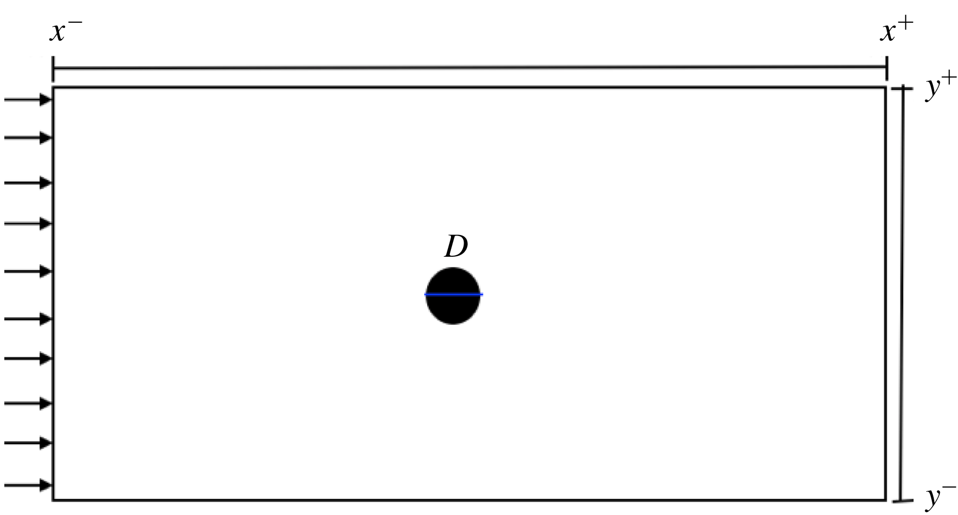
Schematic diagram of a representative flow past a circular cylinder.

3 Numerical methodology
Numerical results were obtained using the Nektar++ software, which is an open-source code based on the Spectral/hp Element Method (Karniadakis & Sherwin Reference Karniadakis and Sherwin2005). A second-order stiffly stable time-stepping scheme (Karniadakis, Israeli & Orszag Reference Karniadakis, Israeli and Orszag1991) was employed to advance the solution of the perturbation in time, while numerical evaluation of the dynamic response of the cylinder was carried out using a Newmark-
 $\unicode[STIX]{x1D6FD}$
solver (Newmark Reference Newmark1959). The generalised eigenvalue problem
 $(\unicode[STIX]{x1D740}\mathbb{B}+\mathbb{L})\boldsymbol{\cdot }\widehat{\boldsymbol{q}}=\mathbf{0}$
was solved by using the Arnoldi method (Saad Reference Saad1992).
Figure 1 represents the geometry of interest. We considered a circular cylinder of diameter
 $D=1$
. This solid body was immersed in an uniform flow of magnitude
 $U$
parallel to the
 $x$
-axis, pointing to the
 $x^{+}$
direction. The origin of the coordinate system was at the centre of the cylinder with dimensions:
 $x^{+}=45D$
downstream,
 $x^{-}=-25D$
upstream and
 $y^{\pm }=25D$
cross-stream. For the base and perturbation fields, Neumann high-order conditions for pressure (Karniadakis et al.
Reference Karniadakis, Israeli and Orszag1991) were imposed at the inlet and the wall of the cylinder and Dirichlet boundary conditions were applied for the velocity fields. In the non-inertial frame of reference method, these conditions were as follows: at the inlet,
 $\boldsymbol{U}=(1,0)$
for the base flow calculations,
 $\boldsymbol{u}^{\prime }=\dot{\boldsymbol{y}}^{\prime }$
for the linear stability analysis and
 $\boldsymbol{u}=\dot{\boldsymbol{y}}$
for the nonlinear calculations; and at the cylinder wall,
 $\boldsymbol{U}=\mathbf{0}$
,
 $\boldsymbol{u}^{\prime }=\mathbf{0}$
and
 $\boldsymbol{u}=0$
for base flow, linear stability and nonlinear calculations, respectively; and at the outlet,
 $\unicode[STIX]{x1D735}\boldsymbol{U}\boldsymbol{\cdot }\boldsymbol{n}=\unicode[STIX]{x1D735}\boldsymbol{u}^{\prime }\boldsymbol{\cdot }\boldsymbol{n}=\unicode[STIX]{x1D735}\boldsymbol{u}\boldsymbol{\cdot }\boldsymbol{n}=0$
and
 $P=p^{\prime }=p=0$
were imposed for all calculations.
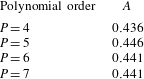
Fluctuation amplitude
 $A$
convergence of the velocity component
 $v$
with respect to the spectral element polynomial order
 $P$
for a flow around a flexibly mounted circular cylinder free to oscillate in the transverse and in-line directions, at
 $Re=60$
,
 $m^{\ast }=5$
,
 $\unicode[STIX]{x1D701}=0$
and
 $V_{r}=5$
.

Linear stability analysis was applied to find the critical Reynolds numbers of the flows around fixed and free-to-oscillate circular cylinders. Next, nonlinear direct simulations were performed to determine the character of the bifurcation. To investigate the flow regimes (steady or unsteady), the component of velocity
 $v$
at an arbitrary point downstream of the cylinder was monitored. The point chosen was
 $(x_{0},y_{0})=(3,0)$
. The numerical simulations were carried out for long enough for the perturbation to settle at either a time-periodic or steady state. The variation of the component
 $v$
was used to classify the flow as steady or time-periodic. We started the nonlinear simulations from a steady solution obtained for
 $Re<Re_{c}$
and gradually increased the Reynolds number until a few units beyond
 $Re_{c}$
. At that point, and indeed for any
 $Re>Re_{c}$
, the flow is time-periodic. Next, we departed from that solution and performed simulations for gradually decreasing Reynolds numbers. If the bifurcation is subcritical, we should observe time-periodic states for a range of
 $Re<Re_{c}$
, which characterises hysteresis. If the bifurcation is supercritical, the amplitude should be zero for any
 $Re<Re_{c}$
.
4 Results and discussions
First, we verified our numerical methodology for the flow around a two-dimensional flexibly mounted circular cylinder. To do that, we performed the convergence analysis, evaluating the amplitude fluctuation
 $A$
of the velocity component
 $v$
at a chosen point in the wake
 $(x_{0},y_{0})=(3,0)$
with respect to the spectral element polynomial order for a flow around a flexibly mounted circular cylinder free to oscillate in the transverse and in-line directions, at
 $Re=60$
,
 $m^{\ast }=5$
,
 $\unicode[STIX]{x1D701}=0$
and
 $V_{r}=5$
. Table 1 shows that polynomials of degree 5 achieved excellent convergence results. To be rigorous, polynomials of degree 6 were used in all the numerical results introduced in this work. Numerical verification continues with the computational simulations of the flow around a circular cylinder allowed to vibrate in the transverse direction at
 $Re=33$
for a range of reduced velocities. The mass ratio
 $m^{\ast }=4.73$
and structural damping
 $\unicode[STIX]{x1D701}=0$
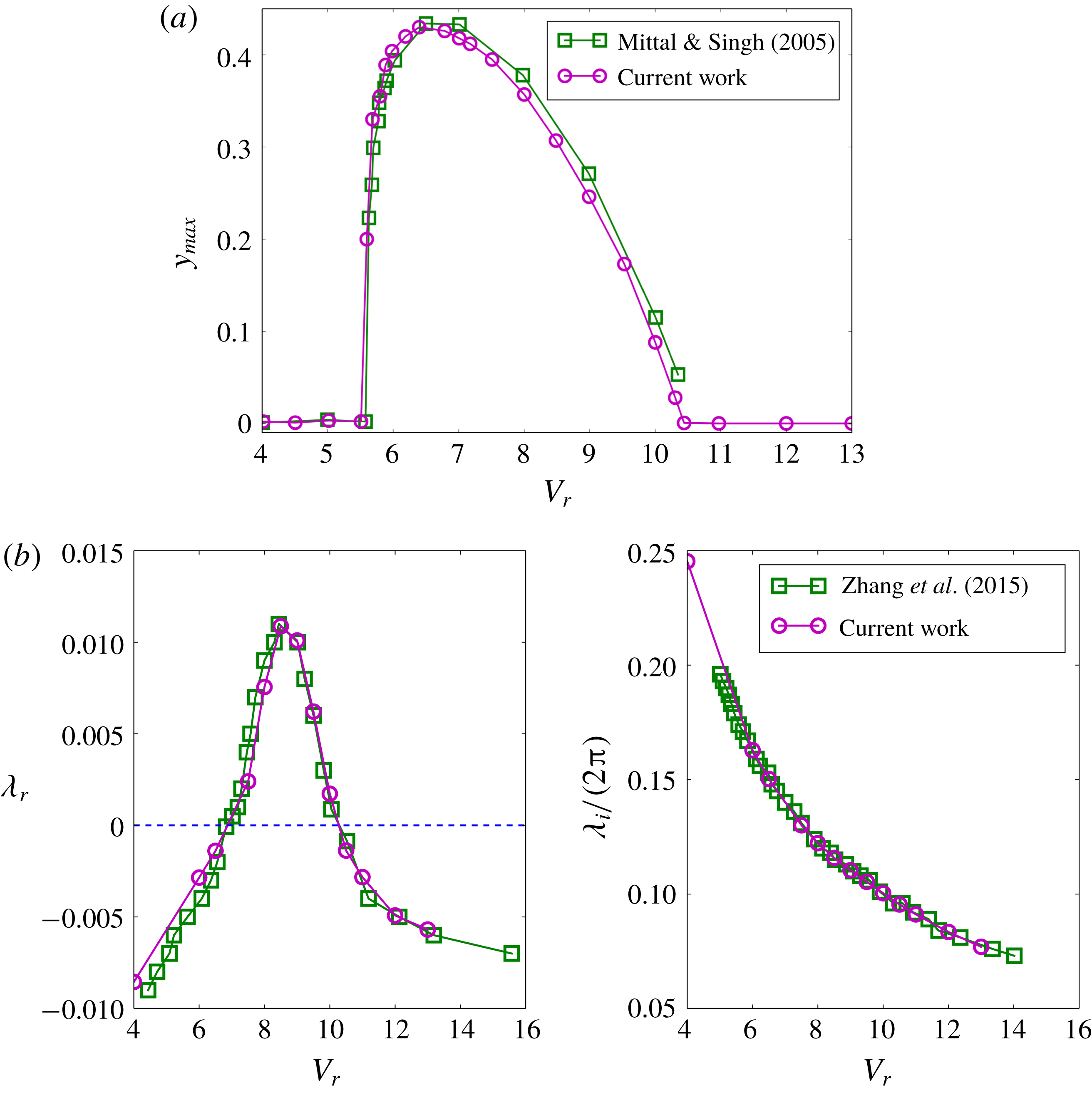
were chosen to match the set-up used by Mittal & Singh (Reference Mittal and Singh2005). Figure 2(a) shows results of cylinder amplitude oscillation
 $y_{max}$
as a function of
 $V_{r}$
obtained by Mittal & Singh (Reference Mittal and Singh2005) and from the current work; the agreement is good. To verify the linear stability analysis, the least stable eigenvalues were computed for different
 $V_{r}$
and compared with the results obtained by Zhang et al. (Reference Zhang, Li, Ye and Jiang2015) at
 $Re=33$
,
 $m^{\ast }=50$
and
 $\unicode[STIX]{x1D701}=0$
. In figure 2(b) it can be seen that the results from our work and those from Zhang et al. (Reference Zhang, Li, Ye and Jiang2015) present a good concordance, for both the real and imaginary parts of the least stable eigenvalue.
(a) Amplitude of cylinder oscillation (
 $y_{max}$
) compared with Mittal & Singh (Reference Mittal and Singh2005), at
 $Re=33$
,
 $m^{\ast }=4.73$
and
 $\unicode[STIX]{x1D701}=0$
; (b) real part
 $\unicode[STIX]{x1D706}_{r}$
(left) and eigen-frequencies
 $\unicode[STIX]{x1D706}_{i}/(2\unicode[STIX]{x03C0})$
(right) of the least stable eigenvalues compared with Zhang et al. (Reference Zhang, Li, Ye and Jiang2015), at
 $Re=33$
,
 $m^{\ast }=50$
and
 $\unicode[STIX]{x1D701}=0$
.

We have also checked our method of nonlinear analysis by applying it to the fixed cylinder case. To do that, first we performed a number of global linear stability analysis calculations to determine the critical Reynolds number. Our results showed that the primary instability occurs at
 $Re_{c_{0}}\cong 46.6$
. This value is in good agreement with the numerical results presented by Jackson (Reference Jackson1987) and Dusĕk et al. (Reference Dusĕk, Le Gal and Fraunie1994). Next, we carried out nonlinear calculations in the vicinity of
 $Re_{c}$
, for increasing and decreasing
 $Re$
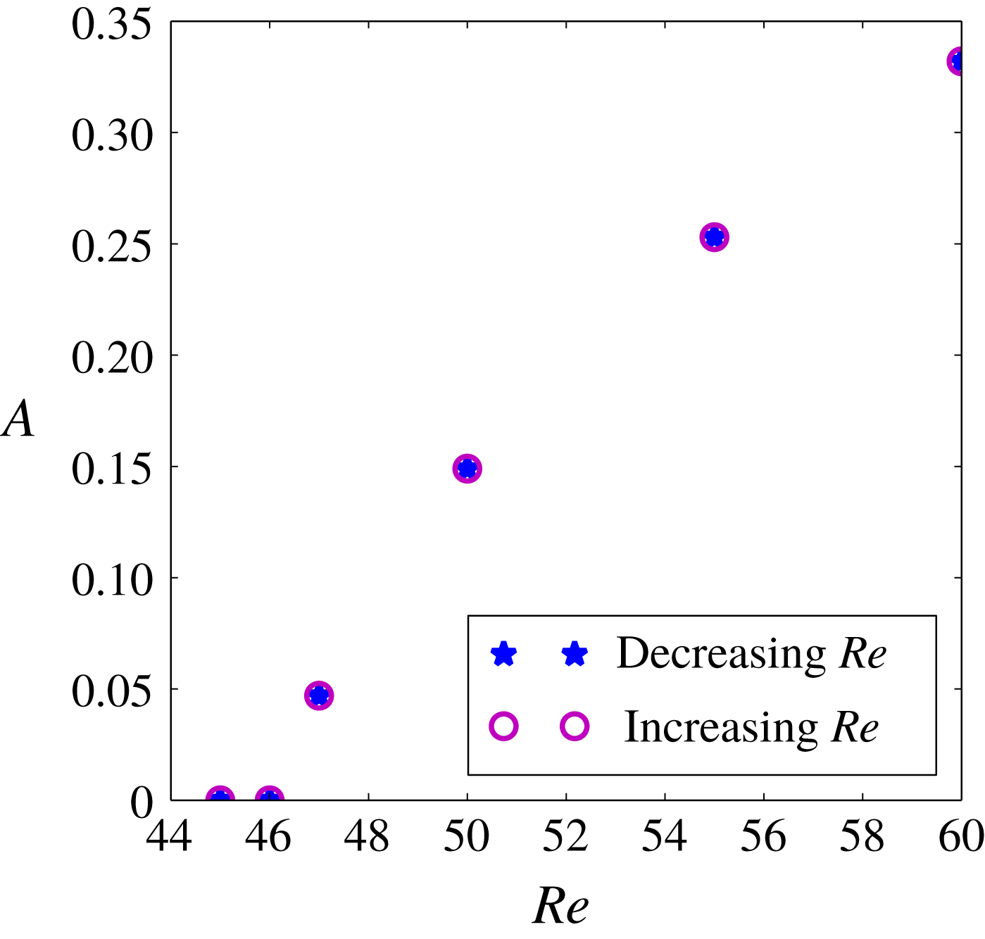
. Figure 3 shows a diagram of the asymptotic perturbation amplitude (amplitude of velocity component
 $v$
at
 $(x_{0},y_{0})=(3,0)$
) as a function of Reynolds number, for both increasing and decreasing Reynolds number calculations. No hysteresis was identified, and the amplitude grows gradually as the Reynolds number is increased beyond
 $Re_{c_{0}}$
. This behaviour characterises a supercritical bifurcation, agreeing with previous studies introduced in the literature (Provansal et al.
Reference Provansal, Mathis and Boyer1987).
Bifurcation diagram for the flow past a fixed cylinder, showing a supercritical character.
 $A$
is the asymptotic amplitude of
 $v$
(
 $y$
component of velocity) at the point
 $(x_{0},y_{0})=(3,0)$
.

Having verified the numerical method, we proceeded to the selection of parameters to be used in the calculations of the fluid–structure interaction cases. Figure 2(a) shows that, for low Reynolds numbers, the lock-in happens for
 $5\lessapprox V_{r}\lessapprox 11$
. So we chose three different values of reduced velocity to investigate: one less than the lower limit of the lock-in range (
 $V_{r}=5$
), one inside the lock-in range (
 $V_{r}=9$
) and one higher than the upper limit of the lock-in range (
 $V_{r}=13$
). Regarding the mass ratio, we selected a low and a high value,
 $m^{\ast }=5$
and
 $m^{\ast }=50$
, respectively. For all cases, the damping parameter,
 $\unicode[STIX]{x1D701}$
, was set to zero. We performed simulations for a flexibly mounted circular cylinder allowed to oscillate in the transverse direction only (1DoF) and in both the transverse and in-line (2DoF) directions. In the 2DoF cases, the structural stiffness was the same for both directions. To find the critical Reynolds number
 $Re_{c}$
, linear stability analysis was applied. Then nonlinear numerical simulations were carried out in the vicinity of
 $Re_{c}$
to verify the bifurcation character. Like the flow around a fixed cylinder, these verification were carried out using the amplitude of velocity component
 $v$
at
 $(x_{0},y_{0})=(3,0)$
.
We start by showing the results obtained for
 $V_{r}$
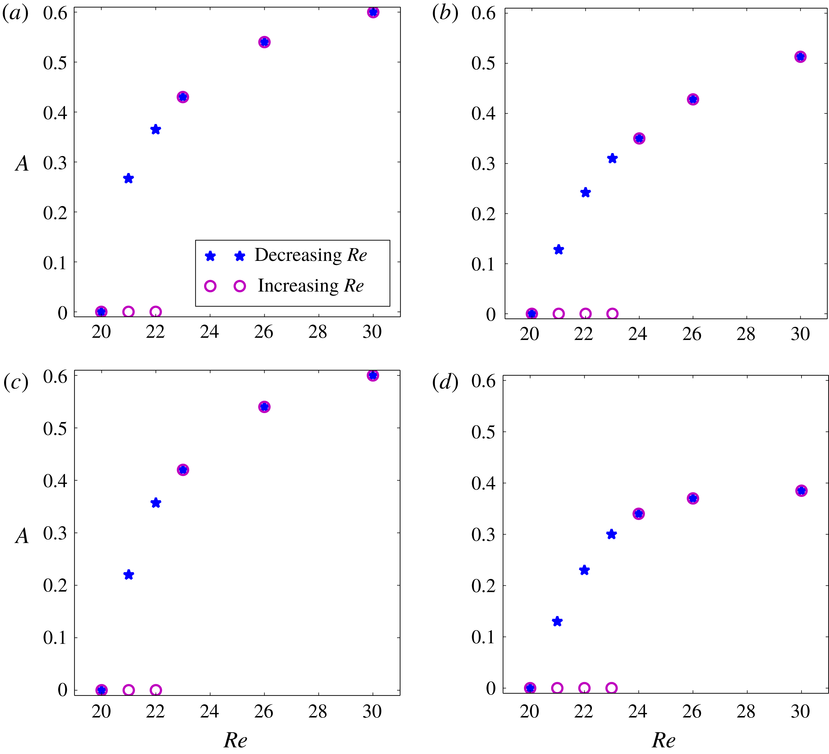
in the lock-in range. Figure 4 displays the primary bifurcation diagram for
 $V_{r}=9$
. Differently from the fixed cylinder case, the subcritical character was verified for both high and low
 $m^{\ast }$
, for 1DoF and 2DoF. For 1DoF and 2DoF, the critical Reynolds was
 $Re_{c}\cong 22$
for
 $m^{\ast }=50$
and slightly higher,
 $Re_{c}\cong 23$
, for
 $m^{\ast }=5$
. Figure 4 shows that the range of hysteresis is larger for
 $m^{\ast }=5$
than for
 $m^{\ast }=50$
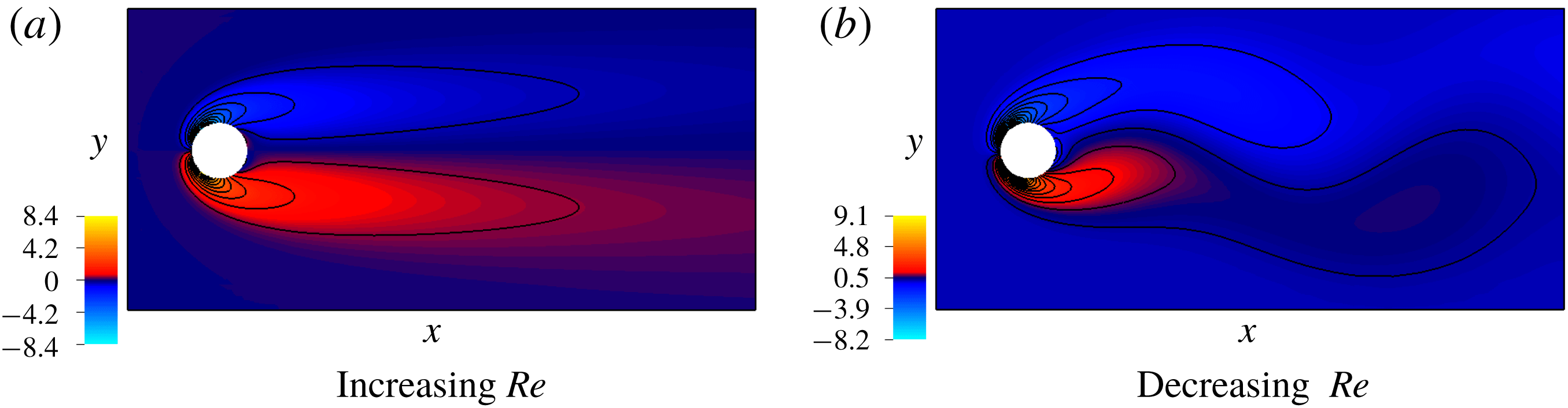
, but in both cases it covers only a few Reynolds number units. Figure 5 shows the vorticity fields for
 $Re=22$
and
 $m^{\ast }=50$
, 1DoF. Figure 5(a) was obtained from a simulation using a steady flow as initial condition. On the other hand, figure 5(b) is the result from a simulation using a time-periodic flow as initial condition, obtained from a simulation carried out at
 $Re>Re_{c}$
. We can see that the steady and time-periodic characters of the initial condition remain in the final solution. In the time-periodic result (figure 5
b), the von Kármán wake is developed, the flow is time-periodic and the flexibly mounted circular cylinder presents a time-periodic oscillation of amplitude
 $y_{max}=0.365$
. For the sake of brevity, we only show results for
 $V_{r}=9$
, but we tested other
 $V_{r}$
values inside the lock-in range and observed the same flow behaviour and subcritical character of the bifurcation.
Bifurcation diagrams at
 $V_{r}=9$
in 1DoF (a and b) and 2DoF (c and d) cases, showing a subcritical behaviour. (a,c) are results for
 $m^{\ast }=50$
with
 $Re_{c}\cong 22$
; (b,d) are results for
 $m^{\ast }=5$
with
 $Re_{c}\cong 23$
.

Vorticity field for
 $Re=22$
,
 $V_{r}=9$
and
 $m^{\ast }=50$
.

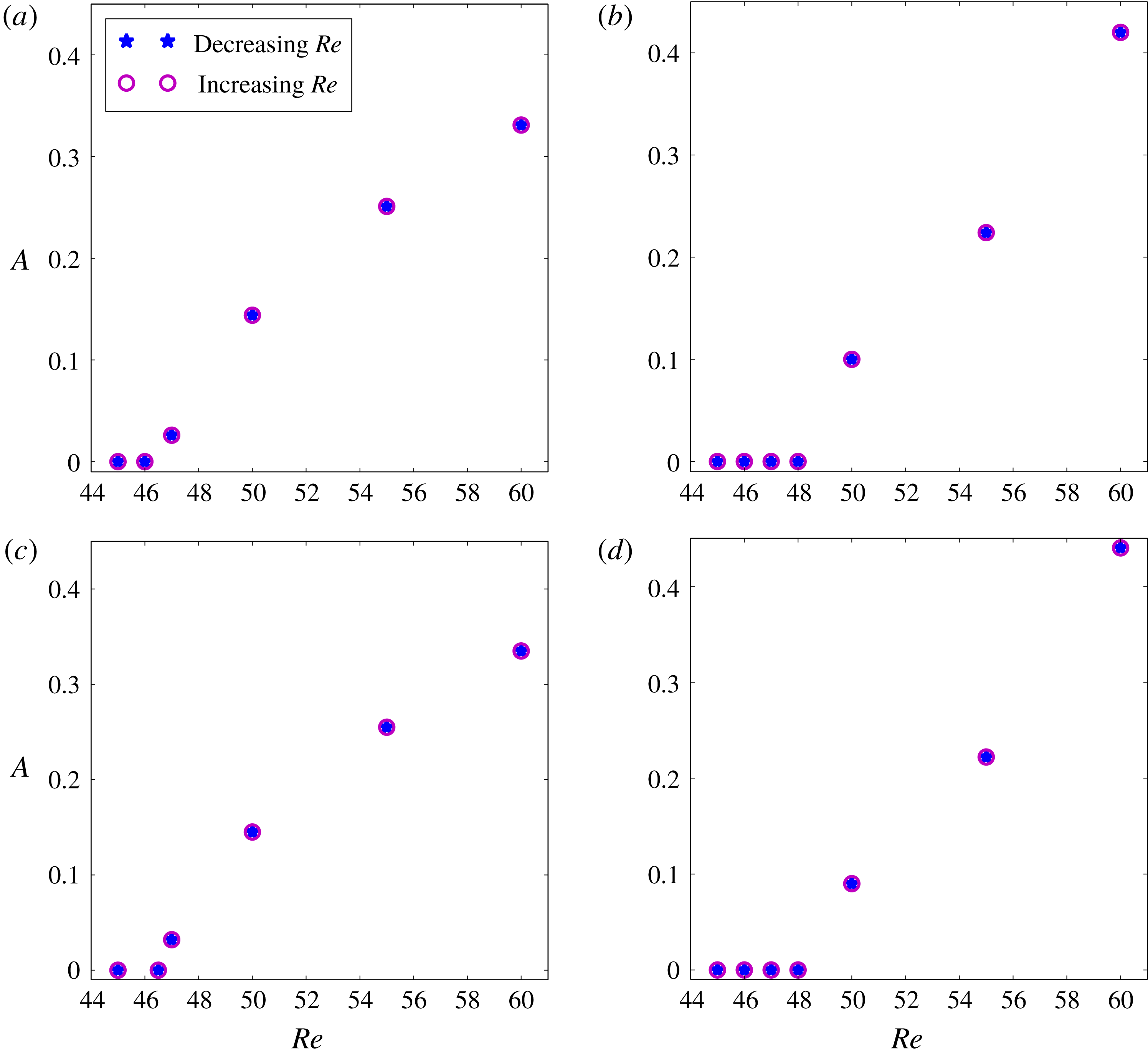
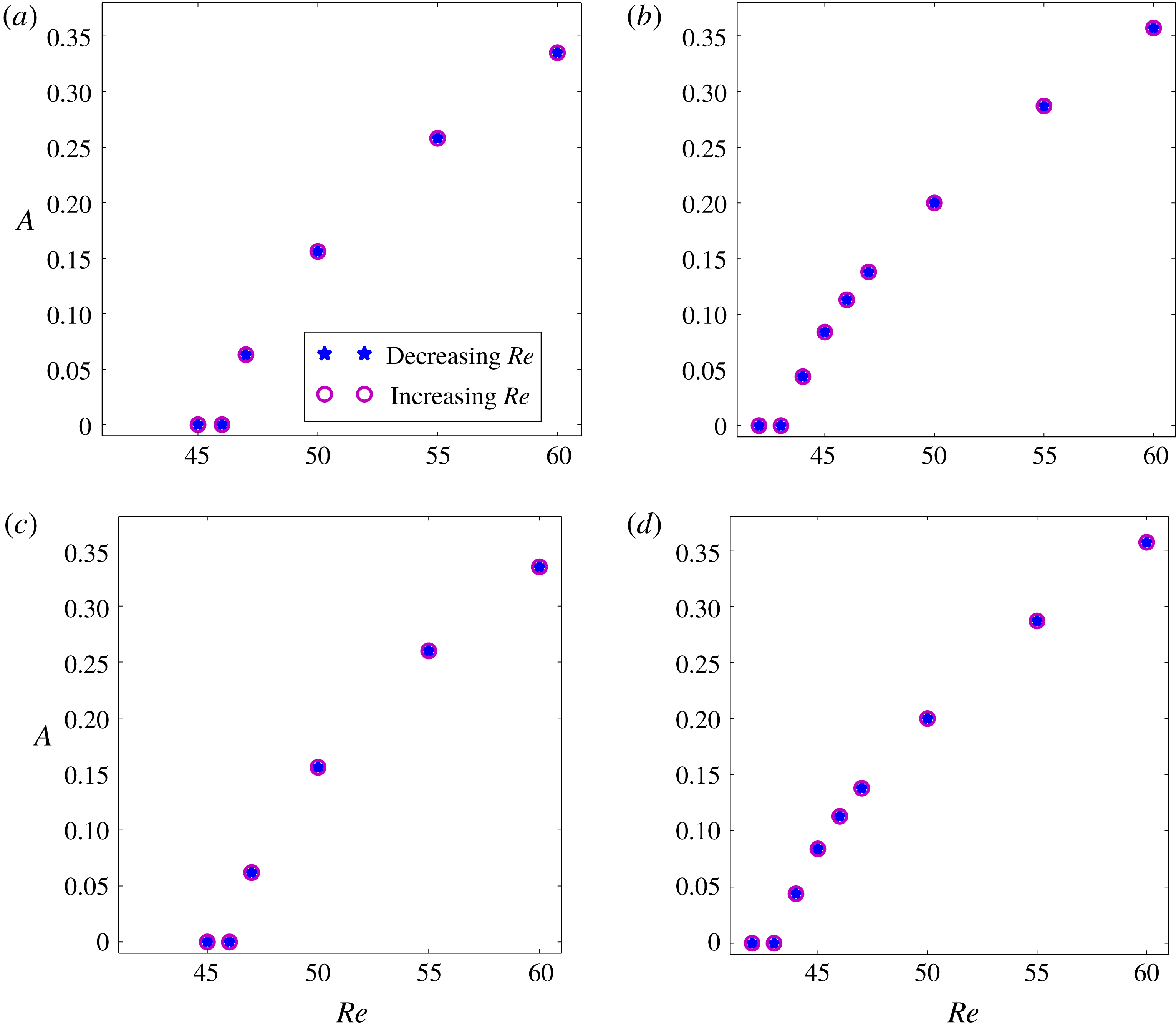
Figures 6 and 7 show the bifurcation diagrams obtained for reduced velocities outside the lock-in range,
 $V_{r}=5$
and
 $V_{r}=13$
. In all these cases, for 1DoF and 2DoF, the primary bifurcation was supercritical, like in the fixed cylinder case. For
 $m^{\ast }=50$
,
 $Re_{c}=Re_{c_{0}}$
(i.e. the critical Reynolds number was the same as that for the fixed cylinder, for both
 $V_{r}=5$
and
 $V_{r}=13$
, and for both 1DoF and 2DoF). In these cases, for
 $Re>Re_{c}$
we observed the von Kármán wake time-periodic flow, but the cylinder did not show any appreciable motion. For
 $m^{\ast }=5$
, the behaviour was different. For
 $V_{r}=13$
, the primary instability happened for
 $Re$
a little lower than
 $Re_{c_{0}}$
,
 $Re_{c}\cong 44$
, while for
 $V_{r}=5$
, the primary instability occurred for a Reynolds number slightly larger than
 $Re_{c_{0}}$
, at
 $Re_{c}\cong 48$
. In both
 $m^{\ast }=5$
cases, for
 $Re>Re_{c}$
the flow became time-periodic and small-amplitude oscillations could be identified. These amplitudes were significantly lower than those observed for
 $V_{r}$
in the lock-in range (
 $y_{max}\cong 10^{-2}$
). It is important to highlight that we are referring to Reynolds numbers not very far from
 $Re_{c_{0}}$
(we have tested
 $Re$
up to 60). As the Reynolds number is further increased, the lock-in
 $V_{r}$
range changes and shows a stronger dependence on the mass ratio too.
Bifurcation diagrams at
 $V_{r}=5$
in 1DoF (a and b) and 2DoF (c and d) cases, showing a supercritical behaviour in all cases. (a,b) are results for
 $m^{\ast }=50$
with
 $Re_{c}\cong 46.6$
; (b,d) are results for
 $m^{\ast }=5$
with
 $Re_{c}\cong 48$
.

Bifurcation diagrams at
 $V_{r}=13$
in 1DoF (a,b) and 2DoF (c,d) cases, showing a supercritical behaviour in all cases. (a,c) are results for
 $m^{\ast }=50$
with
 $Re_{c}\cong 46.6$
; (b,d) are results for
 $m^{\ast }=5$
with
 $Re_{c}\cong 44$
.

5 Conclusions
In this paper, we have shown results from an investigation into the primary bifurcation in the flow around a flexibly mounted circular cylinder. We have employed numerical linear stability analysis to find the critical Reynolds numbers. Next, nonlinear direct simulations in the vicinity of these critical Reynolds were performed to determine the primary bifurcation character. Different values of reduced velocities were tested, covering cases inside and outside the lock-in range. We also employed a low value and a high value of mass ratio (
 $m^{\ast }=5$
and
 $m^{\ast }=50$
, respectively), and we considered transverse only (1DoF) and transverse and in-line motion (2DoF).
The main conclusion was that, like the critical Reynolds number, the nonlinear character of the bifurcation changes completely if the reduced velocity is inside the lock-in range. For those cases, the critical Reynolds number is significantly lower than for the fixed cylinder (approximately 22 versus 47), and the bifurcation is subcritical, in contrast to the supercritical character observed for the fixed cylinder and flexibly mounted cylinder with
 $V_{r}$
outside the lock-in range. In the adopted configurations (range of Reynolds number, mass ratio and reduced velocity), the critical Reynolds numbers do not differ in the cases of 1DoF and 2DoF. We saw that the mass ratio and number of degrees of freedom (1DoF or 2DoF) do not play a relevant role in the results. So we conclude that the changes in both linear and nonlinear responses are due mainly to the proximity of the natural frequencies of the structure and of the flow. It is interesting to note that both the structure system and the coupling between structure and flow are linear, but the frequency tuning is able to change the nonlinear character of the coupled system.
We saw that interesting results can be obtained when tools that are already commonly used to study internal or external flows in fixed domains are employed in fluid–structure interaction cases. We believe that there is much more to be explored if the same tools employed in this work are applied to other fluid–structure interaction problems, or if other advanced numerical tools, such as non-modal stability analysis or adjoint-based sensitivity analysis, are adapted for use in fluid–structure interaction studies.