NOMENCLATURE
- AECMA
-
Association Européenne des Constructeurs de Materiel Aerospatial (European Association of Aerospace Industries)
- DGPS
-
differential global positioning system
- DOE
-
design, operation and environment
- ELOS
-
equivalent level of safety
- FMEA
-
failure modes and effects analysis
- MRB
-
maintenance review board
- MRBR
-
maintenance review board reports
- MSG-3
-
maintenance steering group
- PITVANT
-
Research and technology project in UAV
- SDC
-
system difference code
- SIAGFA
-
Sistema Integrado de Apoio à Gestão da Força Aérea (Air Force Integrated Management Support System)
- UHF
-
ultra high frequency
- WUC
-
work unit code
Symbols
- λ b
-
Failure rate of the known similar system
- λ XA
-
Estimated failure rate of the system X due to failure mode A
- α A
-
Failure proportion in mode A
- k i
-
Stress factor to stress i
1.0 INTRODUCTION
In Portugal, there is an ongoing research and technology project in the field of Unmanned Aerial Vehicles (UAVs) named PITVANT. However, there is not enough knowledge about this type of aircraft to develop an initial maintenance program. Developing such a program is necessary to obtain the required airworthiness certification for aircraft, equipment, components and services before they start operating in the aeronautical sector.
To overcome this difficulty in estimating reliability parameters for new systems, a methodology based on morphological analysis principles was developed to allow the determination of reference failure rates, which will then be used to determine the tasks and intervals for a preventive maintenance program.
2.0 MAINTENANCE REQUIREMENTS
Due to the tight safety requirements in the aerospace industry, all aircraft as well as all products, equipment and parts installed must have a type certificate(1). At this moment a regulatory framework for unmanned aerial vehicles that would allow for the issuance of the type certificates that are similar to other systems operating in the aeronautical sector does not exist. Similar to manned aircraft, the airworthiness certification process for integrating UAVs into national airspace includes fulfilling certain requirements during the development, manufacture and operation of UAVs in order to demonstrate an Equivalent Level of Safety (ELOS) before being operated in non-segregated airspace(Reference Clothier and Rodney2).
In the aircraft industry, the Maintenance Steering Group (MSG-3) methodology is usually used to develop the initial maintenance program as a premise for the development of Maintenance Review Board Reports (MRBR) of the Maintenance Review Board (MRB). This methodology ensures uniformity and compliance to develop minimum requirements for scheduled maintenance in accordance with instructions for continuing airworthiness enacted by most regulatory authorities.
The MSG-3 methodology describes the general organisation and the decision process for determining the requirements for scheduled maintenance that are initially designed to preserve the life of the aircraft and its systems in order to maintain inherent levels of safety and reliability of the aircraft. This methodology divides its analysis and recommended procedures into aircraft systems and power plant, aircraft structures and zonal inspections.
A reliability program is considered to be indispensable to achieve better operational performance through decreased maintenance-related problems in operation and increased flight safety(Reference Marušić, Borivoj and Omer3).
In order to obtain the reliability parameters needed to develop a maintenance program that ensures the required reliability and safety of UAV operation, a methodology was developed integrating the morphological analysis as a means of creating a reliability database for the system.
3.0 MORPHOLOGICAL ANALYSIS
The methodology developed is based on the application of the morphological analysis presented by Andrews and Moss(Reference Andrews and Moss4) to determine the initial failure rate for new equipment.
The morphological analysis is applied in forecasting failure modes and failure rates of new products and services by defining the critical functions and then indicating alternative methods for compliance. This method is valid whenever there are similar products and services and is very useful when there is a lack of data available(Reference Vanston5). Morphological analysis is a powerful method for synthesising systems in several areas to result in a hierarchical framework of a system project, separating all the components, functions and attributes of systems in the analysis(Reference Ayres6). Also, morphological analysis is the preferred method for investigating and identifying the set of configurations and interfaces associated with a given complex problem(Reference Ritchey7).
Generically, this analysis include the following steps: (1) identifying similar equipment where failure rate is known, and (2) comparing and quantifying the design as well as the operating and environmental conditions to determine the average stress factor of the project to be applied to the reference failure rate value.
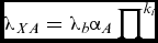
In accordance with Andrews and Moss(Reference Andrews and Moss4), the estimation of failure data for new systems passes in a first instance through the observation of general sources published in books or reliability databases. However, for safety- or production-critical assets, such data could not provide sufficient confidence in the validity of the prediction of failure characteristics. The forecasts carried out through generic databases must be adjusted to the specific conditions under which the system is expected to operate. The recommended model for estimating the failure rate is as follows(Reference Green and Bourne8):
 $$\begin{equation}
{\lambda _{XA}} = {\lambda _b}{\alpha _A}\mathop \prod \nolimits^ {k_i}
\end{equation}$$
where λ XA is the estimated rate of failure mode A of system X, λ b is the failure rate of the similar system X, α A is the failure proportion in mode A, and ki is stress factor due to stress i.
Morphological analysis incorporates the fundamentals of DOE (design, operation and environment). DOE model is based on Moss and Andrews(Reference Moss and Andrews9) research, demonstrating that the failure rates from samples of similar control equipment operating at different conditions had a high range of values. There is typically a ratio of 1:10 between the highest and the lowest failure rate registered. The DOE model uses simple linguistic variables such as: high (high-H), moderate (moderate-M) and low (low-L) having the weighting coefficients (–1), (0) and (+1), respectively. These coefficients are combined into the expected attributes of design, operation and environment, in order to estimate the average weight (X), which is used as an exponent in the expression for determining the modified factor k:
 $$\begin{equation}
k = {2^X},
\end{equation}$$
where X is the average value of the weights of design, operation and environment attributes. It follows the allocation of weights and the determination of the modified k factor. After completion of the determination of reference failure rates, the development of the initial maintenance program based on the MSG-3 methodology can be initiated.
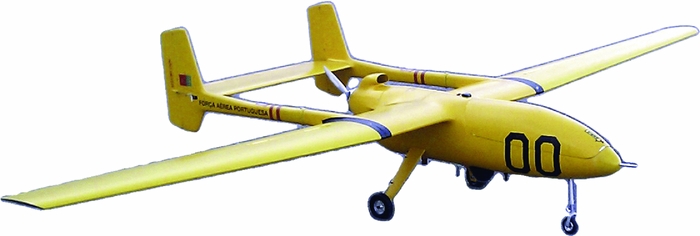
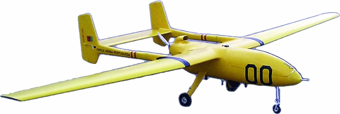
The next section presents a practical example of the application of this methodology to create a reliability database for UAV ANTEX-X02 Extended shown in Fig. 1 developed by the Portuguese Air Force.
UAV Antex-X02 Extended.
4.0 RELIABILITY DATABASE
Once the UAVs developed under the PITVANT project are ready to be integrated into civil society or the Portuguese armed forces, they must undergo a process of airworthiness certification. To develop a maintenance schedule program, it is necessary to know or estimate the failure rates of the inherent equipment and systems. However, the development and manufacture of this type of aircraft is very recent in Portugal. There is little information available related to failure modes and rates, so it is difficult to determine reliability parameters underpinning a maintenance program.
Due to the problem of lack of information available on these systems and the associated need to certify them, a method was developed to create the initial maintenance program for the UAV ANTEX-X02 Extended based on integration of Delphi method, morphological analysis, and failure modes and effects analysis (FMEA).
The Delphi method was used (Phase 2) to allocate weights related to the attributes of design, operation and environment associated to the identified failure modes. Thus, the operational knowledge and expert judgment of the Air Force Academy and other researchers were incorporated into the initial reliability database and identification of similar systems, utilising several rounds of questionnaires to obtain the average value of the stress factor to be applied to the reference failure rates.
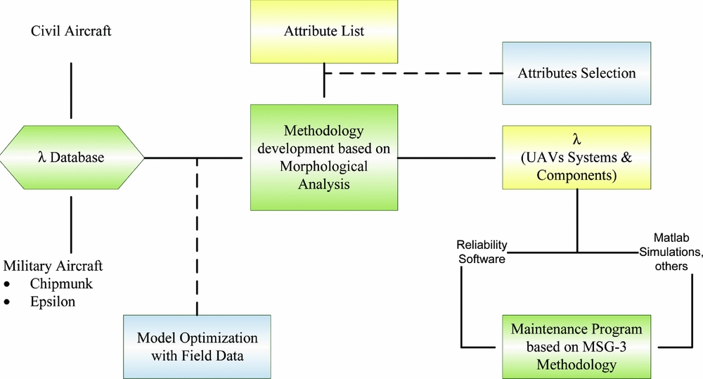
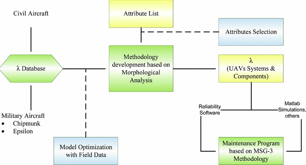
The proposed methodology comprises several stages, starting with data collection related to reference failure rates and finishing with the development of the initial maintenance program of the systems installed on the UAV ANTEX- X02 Extended. The methodology based on the application of the morphological analysis is shown in Fig. 2.
Method based on the morphological analysis.
A more detailed explanation of the method applied follows.
4.1 Phase 1: Database with rates of known failures
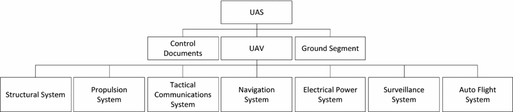
The method applied based on morphological analysis starts with the identification of all systems that comprise the UAV-ANTEX X02 Extended by a functional analysis and decomposition and crating of the internal architecture of the studied aircraft. In this structure, the UAV was divided into three main areas:
-
• Control documents
-
• Aircraft
-
• Ground segment
The study was focused on the aircraft, being analysed its main systems:
-
• Structural system
-
• Propulsion system
-
• Tactical communications system
-
• Navigation systems
-
• Electrical power system
-
• Surveillance
-
• Auto flight system
Figure 3 represents the work done and shows an excerpt of the internal structure of the UAV under study.
Internal architecture of the UAV-ANTEX X02 Extended.
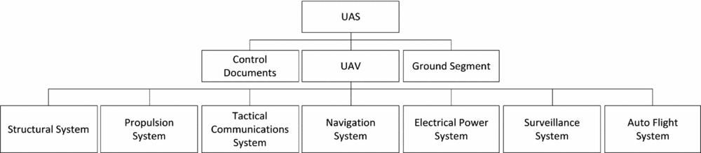
In the above internal architecture, the structural system is generally comprised of five major units: fuselage, wings, stabilising surfaces, controlling flight surfaces and landing gear. Each of these structural subsystems must support forces and moments due to gravity, propulsion and aerodynamic loads.
The propulsion system is responsible for generating the thrust force that propels the aircraft in flight and usually includes the engine (fuel system and propeller) as well as all electronic equipment required for monitoring them.
The tactical communications system is responsible for allowing the realisation of all aircraft communications (ground station/autopilot), and allows communication of embedded sensors. This system consists of three subsystems of communication: UHF communications, iridium communications (satellite communications) and payload communications.
The navigation system is commonly referred to as the avionics component platform. While these instruments do not directly affect the performance of an aircraft in flight, they are important tools for determining the properties and flight performance because they include avionics that are used for guidance functions, navigation and control. This system consists of the transponder system, the DGPS System and the laser altimeter system.
The electrical power system has the function to provide the necessary energy to the other platform systems. To this end it has a power management unit, a generator, batteries for storage and actuators of the system power circuits.
The surveillance system is responsible for enabling the platform of sensors suitable for compliance with responsible missions. This consists of optical sensors (cameras, gimbals, etc.) and electronic devices (frame grabbers, etc.) to allow the capture of the set targets, as well as computational units that not manage them but enable them to run performance algorithms.
The auto flight system is responsible for carrying out the primary navigation and planning the flight, the trajectory forecast, performance calculations and guidance of platforms. It provides an interface with other platform systems. The system consists of hardware and software such as Piccolo, the pitot tube and mechanical actuators.
Since most of the aircraft in service in the Portuguese Air Force have similar systems to those installed on the UAV-ANTEX Extended X02, it was possible to use that aircraft's information as benchmark. Those aircraft have been managed through the years using the maintenance module of the Air Force Integrated Management Support System (SIAGFA) to establish the necessary reliability database. Thus, for the present work all the information concerning the Chipmunk MK 20 aircraft was used to establish the reference failure rates for the UAV.
The data collection process comprised data from failures of five aircraft from 2005 to 2014, resulting in a total of 7,528 work cards.
Following what was established by Andrews and Moss(Reference Andrews and Moss4) for the application of morphological analysis for the determination of the rates of new systems, a detailed analysis was performed to exclude all work cards related to maintenance actions executed on the airbase in response to scheduled tasks, including third-echelon maintenance, inspections, compliance of technical orders and another scheduled maintenance. To determine the reference rates for the ANTEX-X02 Extended, we considered only failures that occurred in Chipmunk aircraft subsystems related to ones existing in the internal architecture of the ANTEX-X02 Extended, and excluding those registered with the failure codes corresponding to ‘no fault’.
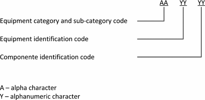
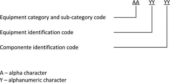
The initial work cards screening brought the identification of 47 different failure modes distributed by different work unit codes (WUC) of the Chipmunk aircraft. A Work unit is the set of numbers assigned to a system, subsystem or component of the aircraft to identify it. In ANTEX-X02 Extended UAV was used the System Difference Code (SDC) referred in AECMA S1000D(10), which also identifies the function of a system/subsystem number as showed in Fig. 4.
Standard numbering system. Terminology for air vehicle, engine and airborne equipment (AECMA S1000D, 1999).
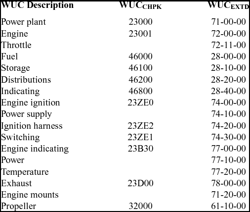
In this way it was necessary to correlate the WUC Chipmunk aircraft and the UAV ANTEX X02-Extended. The results are presented in Table 1 (excerpt).
Correlation between WUC Chipmunk and the UAV ANTEX X02-Extended SDC
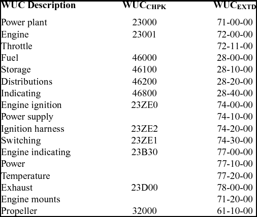
For example, WUC 23000 identifies in Chipmunk aircraft the power plant subsystem. However, in the UAV ANTEX-X02 Extended, this system has the SDC designation 71-00.
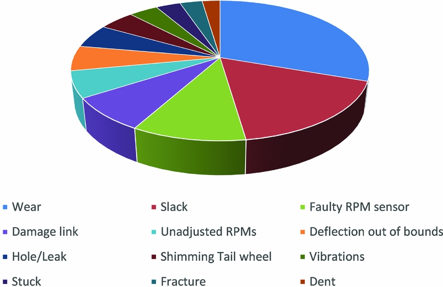
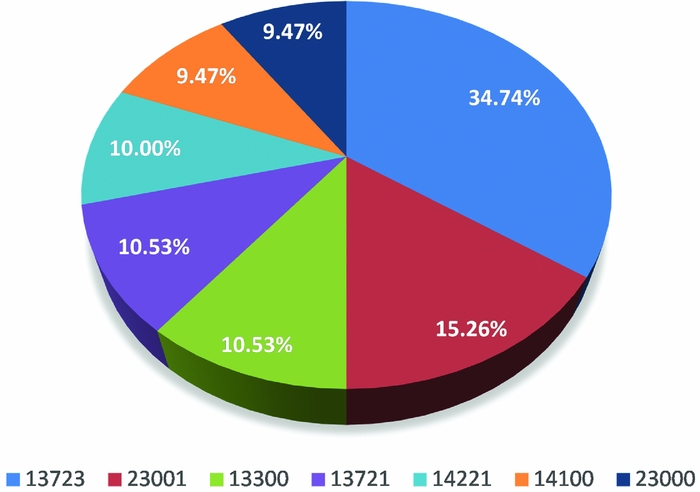
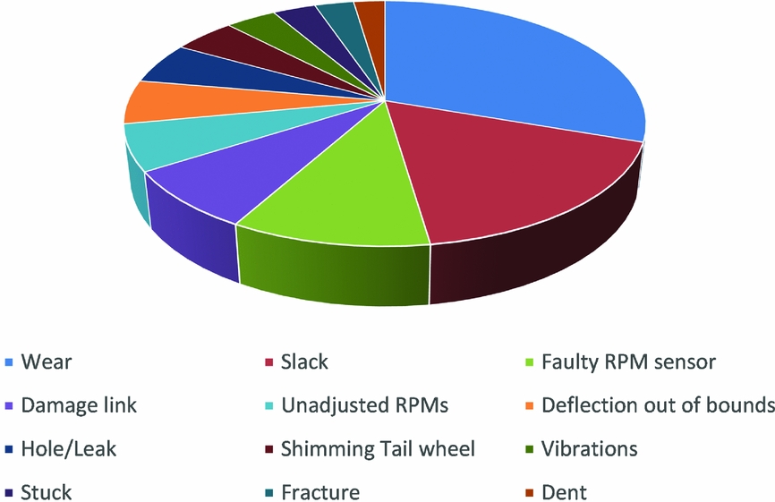
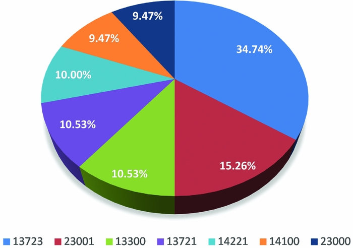
The most significant failure modes were identified by performing by determining the frequency of occurrence of each failure mode to further understand their likelihood in the UAV ANTEX X02-Extended. An analysis was performed on the Chipmunk aircraft systems to identify those who may have greater influence on the aircraft overall reliability, as shown in Fig. 5 for failure modes and in Fig. 6 with reference to WUC.
Failure mode frequency analysis.
Work unit code frequency analysis.
Through a Pareto analysis, it can be seen that the failure modes with higher frequency correspond to wear (23.86%), excessive clearances (13.64%), RPM sensor faulty (8.18%), damaged link (6.14%), RPM misfit (4.77%), deflection out of bounds (4.55%), hole (leak) (4.32%), shimming tail wheel (3.64%), vibration (2.95%), movement (stuck) (2.50%), fracture (2.27%) and dent (1.82%). These will be the failure modes most commonly expected to occur in the UAV ANTEX-X02 Extended.
From the above analysis, it may be concluded that the WUC from Chipmunk aircraft with more significant occurrences are:
-
• 13723 – corresponding to landing gear or tyres (34.74%);
-
• 23001 – corresponding to engine (15.26%);
-
• 13300 – corresponding to landing gear or tail wheel (10.53%);
-
• 13721 – corresponding to landing gear or tyres (10.53%);
-
• 14221 – corresponding to surfaces or flight rudder depth (10.00%);
-
• 14100 – corresponding to flight surfaces or ailerons (9.70%);
-
• 23000 – corresponding to propulsion system (9.70%).
The obtained results from the analysis allow one to foresee which UAV systems will be considered as critical and to know the potential failure modes that could be present on the UAV.
4.2 Phase 2 – Failure rate estimation
The determination of systems failure rate is based on the identification of similar systems (reference) with known failure rates and subsequent comparison and assignment of the design, operation and environment weights. Each one of these categories is evaluated by taking into account some attributes. The obtained result is the mean value of the stress factor to be applied to the failure rate of the reference system.
Using operational knowledge and the expert judgement of Air Force Academy researchers and other recognised specialists, several rounds of questionnaires were administered to obtain the average value of the stress factor to be applied to the reference failure rates. Therefore, for all systems identified (WUC) in the previous phase, the respective weighting coefficient was determined.
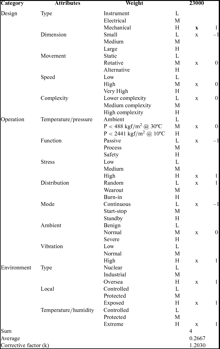
In this paper, the WUC 23000 subsystem will be used to illustrate the proposed methodology. The example presented in Table 2 shows the determination of the weighting coefficient of the stress factor for that subsystem. It was necessary to select the attributes to be evaluated for each category to determine the magnitude of transference from the Chipmunk to the UAV ANTEX X02-Extended. Low (L), moderate (M) or high (H) factors were applied, corresponding to a weight of –1, 0 or 1, respectively, as referred to in Section 3.
Determination of weighting coefficient of the stress factor (excerpt)
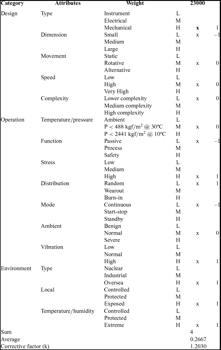
After the corrective factor (k) to be applied to each WUC is determined, we estimate the failure rates for the subsystems related to the product under development. To do so, it is necessary to calculate the proportion of failures (α A ) on the several modes for each WUC through Equation (3):
 $$\begin{equation}
{{\rm{\alpha }}_{{A}}} = \frac{{{\rm{number\ of\ failures\ per\ failure\ mode}}}}{{{\rm{number\ of\ failures\ per\ WUC\ }}}}
\end{equation}$$
The estimation of the reference failure rate (λb ) can be achieved through Equation (4):
 $$\begin{equation}
{{\rm{\lambda }}_{{b}}} = \frac{{{\rm{number\ of\ failures\ per\ WUC}}}}{{{\rm{\ total\ hours\ flown\ by\ the\ fleet}}}}
\end{equation}$$
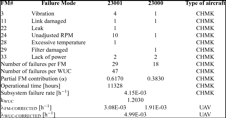
Applying the corrective factor to all failure modes identified, it is possible to determine the failure rate for each failure mode and the consequent WUC failure rate. Table 3 shows an excerpt of the values achieved for a specific subsystem, with reference to those belonging to source (Chipmunk) and the related estimation for the UAV.
Failure rate estimation (excerpt)
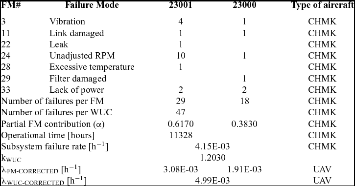
As shown before, both WUC 23000 and WUC 23001 belong to the Chipmunk Propulsion System. Thus, the failure rate for the Chipmunk Propulsion System can be determined (4.15 × 10⁻³) and, when the corrective factor (k) determined on Table 2 is applied, the failure rate for the UAV ANTEX X02-EXPANDED can also be estimated (4.99 × 10⁻³).
The methodology above exemplified was applied to all critical components and systems.
4.3 Phase 3: Maintenance program
The estimated failure rates for all systems of the UAV are fundamental for establish and setting time intervals for preventive maintenance activities. This information serves as the key element to build a so-called UAV maintenance program that fulfils legal requirements to obtain certification and to operate in the airspace. The development of the maintenance program is not presented in this paper. Although this phase is important, the main objective of the present paper is to show a methodology to estimate failure rates when there is no data available and not to establish the UAV maintenance program itself.
5.0 CONCLUSIONS
This paper reported on a research study on progress in Portugal concerning UAV certification and its requirements. The results of the PITVANT project should be integrated into Portuguese Armed Forces and civil society. The UAV under development in this project will have to undergo an airworthiness certification process, including the development of an initial maintenance program.
To do so, it is required to know potential failure modes and to estimate the corresponding failure rates. Due to the lack of available data on these systems and the need to certify the new UAV, a methodology was developed based on morphological analysis that allows estimating the initial failure rates of new systems that are needed to develop the initial maintenance program required in the certification process of these systems.
This paper showed a method for determining the necessary information concerning the development of an initial maintenance program for UAV ANTEX-X02 Extended based on the failures and failure rates of the Chipmunk MK 20 aircraft. The obtained results allow the establishment of an initial maintenance program for the UAV under study, thus satisfying one of the requirements of the airworthiness certification process. The methodology is suitable for application to other items or products under development and in situations where there is not sufficient previous related field data.
In future work, an initial maintenance program resulting from the application of this methodology to create a reliability database will be presented.