Introduction
The field characteristics of a remarkably well-exposed shallow intrusive complex in the Ferrar large igneous province (LIP), at Allan Hills, south Victoria Land, reveal the evolution of a network of dykes and sills. We assess the interactions among individual intrusions, their mechanics of emplacement and their relationships with volcaniclastic deposits in-filling an apparently coeval maar structure. Our conclusion is that local stresses induced by magmatic injection were more important than regional ones in controlling intrusion geometries at Allan Hills.
The Ferrar large igneous province
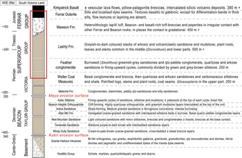
The onset of Early Jurassic continental flood basalt volcanism in South Africa, South America and Antarctica marked the initial breakup of the Gondwana Supercontinent (Storey Reference Storey1995, Elliot & Fleming Reference Elliot and Fleming2000). In Antarctica large volumes of tholeiitic magmas were erupted and emplaced in less than one million years, producing the Ferrar LIP. The province is dated at c. 183.6 ± 1.0 Ma (U-Pb ages, see Encarnaciòn et al. Reference Encarnaciòn, Fleming, Elliot and Eales1996) and products of Ferrar magmatism, known as the Ferrar Supergroup, crop out in Tasmania, south-east Australia, New Zealand and Antarctica, in one of the most extensive continental flood-basalt provinces on Earth. Its total volume is estimated to exceed 2.3 x 10⁵ km3 (Elliot & Fleming Reference Elliot and Fleming2004). In Antarctica the Ferrar Supergroup can be observed for over 3500 km, from the Theron Mountains to Horn Bluff. Intrusive Ferrar rocks consist of the Dufek layered mafic intrusion, the Butcher Ridge igneous complex (e.g. Behrendt et al. Reference Behrendt, Damaske, Finn, Kyle and Wilson2002) and dykes and sills of the Ferrar Dolerite. Extrusive rocks comprise the Mawson Formation mafic volcaniclastic deposits and correlatives, and the overlying Kirkpatrick Basalt. All these units intrude and/or overlie Devonian–Triassic sedimentary rocks (Beacon Supergroup, Figs 1 & 2), basement granitoids and meta-sedimentary rocks (Fig. 2).
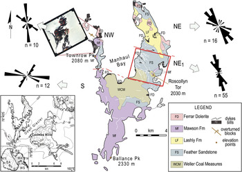
Inset, bottom left corner: study area. The red box along the Transantarctic Mountains encloses the region where Allan Hills is located in south Victoria Land. EA = East Antarctica, RS = Ross Sea, WA = West Antarctica, WS = Weddell Sea. Centre: bedrock geology (modified from Grapes et al. Reference Grapes, Reid and McPherson1974) and photogeological map of Allan Hills. The nunatak is subdivided into four areas (NW, NE, NE1 and S) where Ferrar Dolerite intrusions with different characteristics are exposed. Dashed red lines help visualize the boundaries of the four areas. Rose diagrams show the average trends of the dykes identified within each area. The aerial photograph beside area NW shows the locations (circled areas) of country rock blocks with anomalous vertical bedding, i.e. overturned. More detailed distinction of Ferrar Dolerite intrusions is made upon field relationships observed in the boxed area, represented and discussed further in this paper.

Stratigraphy of south Victoria Land: boxed area encloses rock types exposed at Allan Hills (modified from White et al. Reference White, Bryan, Ross, Self and Thordarson2009).

The doleritic sills and shallow dyke complexes of the Ferrar Dolerite form the greatest proportion of the preserved Ferrar Supergroup. Excellent exposures are found in the McMurdo Dry Valleys, south Victoria Land. Here, large tholeiitic sills prevail over dykes. Outstanding examples are c. 5000 km2 in areal extent and average 350–450 m in thickness, some are more than 700 m thick (Marsh & Zieg Reference Marsh and Zieg1997). Stacks of thin (0–50 m) sills become more common in the upper levels of the Beacon Supergroup sequence (Victoria Group) where they ascend the stratigraphy in ‘step-wise’ fashion (“transgressive sills”, see Table I and references therein).
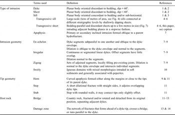
List of terms used to describe the types of intrusion, their geometry and that of their tips, and main deformation features observed in the host rock.

References: 1 = Anderson (Reference Anderson1951), 2 = Annels (Reference Annels1967), 3 = Mudge (Reference Mudge1968), 4 = Walker (Reference Walker1999), 5 = Chevallier & Woodford (Reference Chevallier and Woodford1999), 6 = Goulty (Reference Goulty2005), 7 = Hoek (Reference Hoek1991), 8 = Pollard et al. (Reference Pollard, Muller and Dockstader1975), 9 = Pollard et al. (Reference Pollard, Segall and Delaney1982), 10 = Skilling et al. (Reference Skilling, White and McPhie2002), 11 = Rickwood (Reference Rickwood1990), 12 = Delaney & Pollard (Reference Delaney and Pollard1981), 13 = Delaney et al. (Reference Delaney, Pollard, Ziony and Mckee1986), 14 = Weinberger et al. (Reference Weinberger, Lyakhovsky, Baer and Agnon2000). For the term ‘transgressive sheet’ see also the section on intrusion mechanics and nomenclature, and Figs 4 & 7.
Dykes are volumetrically unimportant compared to the sills (Gunn & Warren Reference Gunn and Warren1962, Elliot & Fleming Reference Elliot and Fleming2004, Marsh Reference Marsh2004). Regional dyke swarms found in other LIPs (e.g. Ernst et al. Reference Ernst, Head, Parfitt, Grosfils and Wilson1995) and rift systems (e.g. Walker Reference Walker1999 and references therein) are inferred from aerogeophysical data in the Dufek massif (Ferris et al. Reference Ferris, Storey, Vaughan, Kyle and Jones2003), but not observed elsewhere. Tight clusters of shallowly dipping dolerite intrusions are reported from only a few other localities in the central Transantarctic Mountains (e.g. Hornig Reference Hornig1993, Leat Reference Leat2008 and references therein) and south Victoria Land (Skinner & Ricker Reference Skinner and Ricker1968, Morrison Reference Morrison1989) and in places are interpreted as the result of cracking of the host rocks ahead of sill fronts (Grapes et al. Reference Grapes, Reid and McPherson1974, White et al. Reference White, Bryan, Ross, Self and Thordarson2009). At Allan Hills, Ferrar dykes intrude the top units of the Beacon sequence and the overlying or inset pile of Mawson volcaniclastics (Ross et al. Reference Ross, White and McClintock2008 and references therein) (Figs 1 & 2). The network of dykes and sills forms a shallow intrusive system whose overall structure and significance have been only partially studied (Grapes et al. Reference Grapes, Reid and McPherson1974).
Development of the Ferrar LIP in a failed rift arm during early rifting of Gondwana along its palaeoPacific margin has been proposed on the basis of: a) parallelism between Ferrar dykes and (inferred) Jurassic faults in the central Transantarctic Mountains (Wilson Reference Wilson1993), b) a rift-orthogonal stretching scenario from subglacial geophysical measurements in the Transantarctic Mountains (Ten Brink et al. Reference Ten Brink, Hackney, Bannister, Stern and Makovsky1997), and c) the assignment of monoclinal structures and arkosic sediments associated with volcaniclastic deposits to rift-margin settings (Elliot & Larsen Reference Elliot and Larsen1993). However, alternative models have been proposed to account for the absence of regional intrusion trends and fracture systems consistent with an extensional regime (Elliot & Fleming Reference Elliot and Fleming2004). Field observations and photogeological analysis of brittle and ductile structures of south Victoria Land support reactivation of basement structures during successive episodes of tectonism and magmatism in Mesozoic and Cenozoic times (Jones Reference Jones1997), though Elliot (personal communication 2009) notes that this part of south Victoria Land may not fully represent the entire Transantarctic mountain belt. Mesozoic fault sets with displacements greater than a few metres are not recorded from geophysical surveys and are not observed in the field (e.g. Behrendt et al. Reference Behrendt, Damaske, Finn, Kyle and Wilson2002, Ferris et al. Reference Ferris, Storey, Vaughan, Kyle and Jones2003). All well-documented rift-defining faults are disseminated across the Ross Embayment, and from the central Transantarctic Mountains through north Victoria Land. Such faults are commonly transtensional in character, associated with alkaline dyke swarms, and appear related to extension of the West Antarctic rift system into the Ross Sea in the Cenozoic or later (Trey et al. Reference Trey, Cooper, Pellis, Vedova, Cochrane, Brancolini and Makris1999, Storti et al. Reference Storti, Salvini, Rossetti and Phipps Morgan2007).
Intrusive mechanics and nomenclature
Magma propagates through crustal rocks before erupting at the surface. Variably extensive intrusive complexes may form as a result of magma intrusion at depth, and may also connect to volcanic systems at the surface (e.g. Walker Reference Walker1999). Igneous intrusions are magma driven hydro-fractures, whose genetic mechanisms are incompletely known. Hydro-cracks initiate at small-scale mechanical/physical heterogeneities around the magma source and subsequently evolve under control of: a) gradients of local shear strain-rate and melt pressure, b) a complex interplay of those gradients, fracture toughness and rheology of the host rock in response to magma injection, and c) ‘buoyancy’, i.e. the density contrast between magma and host rock (e.g. Lister & Kerr Reference Lister and Kerr1991, Rubin Reference Rubin1995). Variations in tectonic stress regimes and magma-supply rate, and presence of pre-existing structural discontinuities may affect the intrusion dynamics, and consequently the size and geometry of the resulting intrusive complexes.
Hypabyssal basalt bodies emplaced along cracks have a range of orientations: “sills” are bedding-concordant intrusions (Mudge Reference Mudge1968), “dyke” intrusions are bedding-discordant. Annels (Reference Annels1967) distinguished between steeply dipping dykes (dip ≥ 60°) and shallowly dipping “sheets” (dip < 60°) in south-east Iceland. The same terminology (also in Table I) is applied to the Ferrar Dolerite intrusions at Allan Hills. “Transgressive” intrusions are sill-type bodies that can be demonstrated in outcrop to link at different stratigraphic levels by means of a shallow-dipping sheet, as also noted previously by Grapes et al. (Reference Grapes, Reid and McPherson1974) and Elliot & Fleming (Reference Elliot and Fleming2004, Reference Elliot and Fleming2008). Features of this sort are “transgressive sills”, whereas small structures (a few metres in along-dip dimension), interconnected across adjacent bedding planes, are “transgressive sheets”.
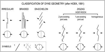
In the following sections, Allan Hills intrusions are subdivided into four basic geometries (Hoek Reference Hoek1991 and here summarized in Fig. 3) based on morphology and arrangement of individual segments and surface deformation features at, or around, dykes and sills (e.g. Delaney et al. Reference Delaney, Pollard, Ziony and Mckee1986, Weinberger et al. Reference Weinberger, Lyakhovsky, Baer and Agnon2000). These features are then used to interpret local syn-intrusive thermo-mechanical conditions and rheology of magma at Allan Hills.
Schematic representation of classified dyke geometries (modified after Hoek Reference Hoek1991). Parameters used for this classification are: the orientation of segments and dyke envelope, mutual relationships between segments, and orientation of the dilation vector (see text). Symbols: 1 = dyke segments, 2 = fractures, 3 = stereonet showing clustering of poles to dyke planes with respect to the trace of the dyke envelope (dashed line across stereonet). The arrows both beside schematized dykes and relative stereonets indicate the orientation of the dilation vector with respect to the overall intrusion.

Allan Hills
The nunatak Allan Hills is situated c. 8 km west of the Convoy Range (Fig. 1). It exposes high-level parts of the Ferrar igneous system. Thick (c. 400 m) piles of volcaniclastic Mawson deposits dominate in the southern part of the nunatak (Elliot & Fleming Reference Elliot and Fleming2008, Ross et al. Reference Ross, White and McClintock2008). No remnants of overlying Kirkpatrick Basalt lava flows are known. Ferrar Dolerite transgressive intrusions and clusters of dolerite sheets ascend towards the Jurassic palaeosurface, intruding the flat-lying units of the Victoria Group. On the steeper slopes of Roscollyn Tor, dykes accompany sills interleaved with deposits of both the Lashly and Mawson formations (Ross et al. Reference Ross, White and McClintock2008).
Ferrar intrusions were studied by combining photogeology with field data. Vertical and oblique aerial photos of five adjacent flight lines over Allan Hills were analysed in order to identify relevant fracture systems and/or dyke sets across the outcrop area and target areas for the field-study, and to characterize the intrusions in size and distribution. The scale of the aerial photographs is 1:24 000, which would set the lowest limit of identification of geological features at c. 25 m. The smallest features resolvable on the aerial photographs were found in the field to be 30 m wide.
The following section focuses on dyke characterization. “Dyke orientation” is the average orientation of individual dyke-segments. Sets of segments with a coherent overall trend were mapped as a single dyke, except when separated by visible offset. Large sills were inferred to be present where erosional terraces that end abruptly at dolerite dominated cliff faces are covered by dolerite scree. Individual dolerite sheets exhibit a variety of geometric features and relationships with their host rocks. They provide a record of the structural evolution of the area and mechanical response of the country rocks to magmatism.
Photogeology and field relationships
Allan Hills exposes large sills, transgressive dolerite sheets, and a number of segmented inclined sheets. Four areas (denoted NW, NE, NE1 and S; see key and caption to Fig. 1, also Ross et al. (Reference Ross, White and McClintock2008)) are differentiated by intrusion type, dyke-density and pattern.
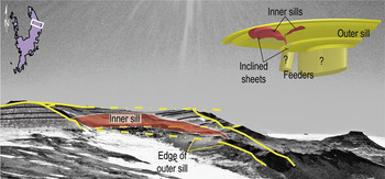
The northernmost edge of the western arm (NW) and its small outliers to the north are almost entirely made of dolerite. Masses of layered Beacon rocks exhibiting subvertical bedding are ‘floating’, enclosed within the dolerite mass. Isolated sill outcrops are observed on cliff faces along both the perimeter of area S and the easternmost edge of area NE1. In area NE, flat-lying Beacon layers alternate with bedding-parallel dolerite sills. In places, such sills can be seen to ‘climb’ the sedimentary layering as interconnections of shallow-dipping dolerite sheets (transgressive sills, Fig. 4).
Mountains of the eastern arm, view to north-east. Lines and patterns in the foreground highlight a set of transgressive sills. The conceptual model is shown on the top-right corner of the picture (modified after Chevallier & Woodford Reference Chevallier and Woodford1999). Geometry of the feeders is unknown. The outer sill is a continuous intrusive body. The yellow outlines over the photo represent the edge of the outer sill in outcrop (continuous line = visible edges, dashed line = inferred or prolonged contacts). The inner sill (red shading) is nested over the walls of the outer one. Only the almost parallel walls of the two nested structures are visible in the photo. Continuous black lines are used for bedding contacts.

At least 93 Ferrar Dolerite dykes, comprising over 130 segments, are scattered across all four areas and overall present a variety of alignments and sizes. Only twelve east–west trending sheets could be identified in central, southern Allan Hills (S in Fig. 1), where they intrude pyroclastic density current and debris avalanche deposits (Elliot & Larsen Reference Elliot and Larsen1993, Reubi et al. Reference Reubi, Ross and White2005, Ross et al. Reference Ross, White and McClintock2008). Similarly, the sixteen dykes scattered across the eastern arm (area NE) have variable trends. The dykes (n = 10) that are exposed in the western arm are sub-parallel to one another and strike north-west. A more numerous cluster of dykes (n = 55) is located south of north-east Allan Hills (in area NE1) and has an average trend of N343° (Fig. 1).
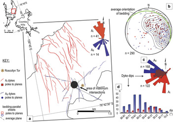
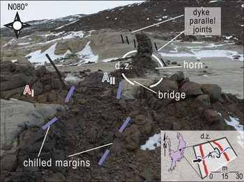
Detailed field study was performed in area NE1. Here, field measurements of dyke orientation (map and diagrams in Fig. 5) and field relationships (Fig. 6) reveal two generations of dolerite sheets, AI and AII.
Enlargement of the photogeology for NE1. Key to map and diagrams: red symbols refer to AI dykes, blue ones to AII cluster and coloured lines on the map are dykes. Straight black lines on the map define the best-fitting trends of the segmented AII intrusions. The area where such dyke-paths intersect is represented by a black circle. a. Rose diagrams showing trend of the cluster of intrusions within NE1 (photogeological estimates). b. Stereo-plot (equal area projection, lower hemisphere) of measured orientations collected along 13 representative sheets. Dyke orientations are plotted both as poles to planes (red squares and blue dots, for AI and AII sets, respectively) and with a density diagram. Hollow poles to planes at the centre of the projection refer to sill-type portions of transgressive sheets. The un-dashed great circle represents the average bedding orientation, sub-parallel to the orientation of the sill transgression and perpendicular to the majority of dyke measurements. c. Analysis of dyke-dip measurements. The Rose diagram shows the prevailing westward dip of all intrusions. East dips, collected along the walls of transgressive sheets, characterize dolerite bodies belonging to either set, but are more frequent for AI intrusions. d. Frequency histogram of dyke-dip distributions, separating into 10° classes the measurements collected along dykes of each of the dyke sets.

A short segmented AII dyke intersects a dyke of the other set. Sledge hammer for scale and viewing direction shown with a black arrow on the inset diagram. Chilled dolerite margins parallel to the younger dyke highlight the crosscutting relationship. A horn and its associated bridge characterize the damage zone (d.z.) between the two contiguous AII segments, east of the cross-cut (inset sketch).

AI sheets are aligned NW–SE in a sub-parallel swarm. Individual intrusions do not exhibit significant deviations in strike but dip most shallowly in the south-west and north-west directions (Fig. 5c–d). Some of them are intersected by dykes of the AII set (Fig. 6). This second set of intrusions, characterized by a larger distribution of orientations and steeper dyke margins (Fig. 5b), defines a sub-radial array which converges west of Roscollyn Tor. The area where AII intrusions intersect has been reconstructed by prolonging their average strike (Fig. 5; method of the ‘maximum intersections’, after Ancochea et al. Reference Ancochea, Brändle, Huertas, Hernán and Herrera2008).
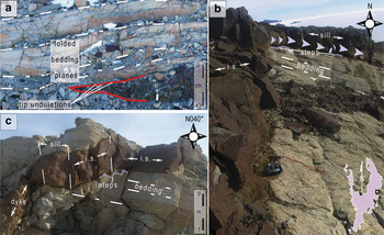
Dykes in area NE1 cover the entire range of dip magnitudes (0–90°), with most values < 60°, in directions opposite to that of host rock bedding (insets in Fig. 5). Much shallower dip values were recorded at east-north-east dipping sheet-margins, corresponding to transgressive sheets propagated along bedding. Arrested tips of trangressive intrusions or dyke-sill transitions are exposed in only a few places. At the tips of the sills, where exposed, there is gentle folding of the immediately overlying host rock layers (Fig. 7a). Alternating dykes, inclined sheets and sills of variable size and orientation form the transgressive intrusions. At local outcrop exposures, sill footwalls are characterized by small steps trending in a down dip direction, along bedding (Fig. 7b & c).
a. Deformation of mudstone layers of the Lashly Formation around the tip of a sill located south-west and c. 300 m in elevation below Roscollyn Tor. Gentle folding of bedding around the undulating tip of the sill (red outline) is highlighted by the dashed lines, folding diminishes significantly in < 1 m above the tip. b. A transgressive sheet emplaced across and along the country rock bedding planes. Inclined dolerite sheets (i.s.) interconnect short sill-type portions. c. Small steps observed along the same transgressive intrusion show bedding-parallel propagation of magma at the time of its emplacement. A geologic compass is used for scale.

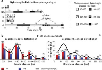
Lengths of dykes from photogeological analysis and field measurements of segment length and thickness are presented in Fig. 8a–c. The intrusions are 30–1500 m long, with a mean length of 375 m for the overall population. The greatest variability of dyke length is recorded in NE1, with other areas having more consistent distributions (Fig. 8a). AI intrusions are 50–1450 m long, and AII dykes between 35 and 785 m. At field-scale, dykes of both sets are broken into segments, mostly < 300 m and as short as seven metres (Fig. 8b). The dykes are 20 cm to 6 m wide, and the predominance of thinner dykes is reflected in the low modal mean width of c. 75 cm (Fig. 8c).
a. Frequency histogram of dyke lengths estimated from aerial photographs. Photogeological dyke lengths are subdivided in length classes and represented for each sub-area at Allan Hills. Overall distribution of dyke and segment lengths is represented by ‘tot’ bar. b. & c. The frequency histograms of dyke-sediment length and thickness, respectively. All data were collected during fieldwork in the most densely intruded area, NE1. In both histograms a black trend line shows the overall distribution (‘total frequency’) of either length or thickness values. Coloured columns represent length or thickness dataset subdivided between the two dyke sets, AI and AII.

Thickness distributions are rather similar for AI and AII dykes. Most dolerite sheets are as thick as 1 m, with thickness remaining constant along strike.
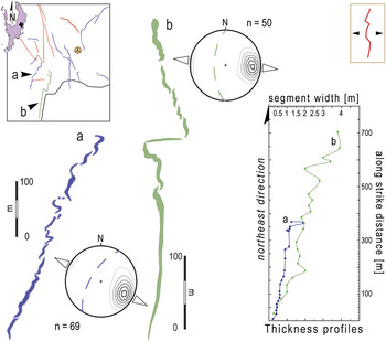
AII dykes show the greater complexity along strike, varying from thin (≤ 2 m) and segmented to long and progressively wider (5–6 m) features as they approach a common intersection, west of Roscollyn Tor. This is represented in Fig. 9. The thickness profiles of two segmented AII intrusions show nearly constant widths along strike for dyke ‘a’, whereas dyke ‘b’ thickens discontinuously towards the north-east.
Field sketches of two segmented AII intrusions (a & b). Poor clustering of their poles to dyke planes (density plots) and heterogeneity of the stepping pattern are consistent with their classification as zigzag dykes emplaced in a homogeneous medium (inset symbol at the top right corner, and see Fig. 3). The sense of dilation is normal to the average trend of each array of segments (dashed great circles). The thickness profile on the right of figure shows the variation in dyke-width along strike (‘north-east direction’) for each one of the represented intrusions.

Dyke geometries
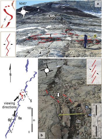
Allan Hills’ intrusions are here described in terms of their overall geometry and the mutual relationships among segments. Most dykes comprise en echelon inclined dolerite sheet arrays with no systematic stepping sense (sketched dykes and Fig. 10b).
Continuation of Fig. 9: examples of some of the geometries described in the text and sketched in Fig. 3. Both photos relate to dyke ‘a’, also sketched in this figure. a. ‘S’-shaped intrusion (1) separated by large offset from its neighbouring segments (2 & 3), person for scale. A plan-view sketch of this dyke is presented to the left of the photograph. The ‘S’ trends sub-parallel to local joints in the surrounding sandstone (N135°, joints labelled as 4) but the dyke rotates into a N170° orientation towards its right-stepping ends. Most dolerite segments align NNW–SSE (e.g. 3); rare segment tips are deflected along the N135° trending joints (2). A through-going fracture (5) propagated ahead of this same dyke termination. b. En echelon segments (6a & b). Sub-parallel margins of baked sandstone (dashed red lines overlain on this photograph) bound laterally an area of intensely crushed country rock (vertical arrow indicating the area) interposed between the dolerite segments, i.e. the probable remains of a zone where their tips had adjoined.

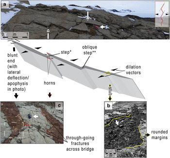
En echelon segmentation increases near the tips of long sheets and locally follows a preferred stepping direction. Single segments cutting sharply through the Beacon host rock are irregular, or zigzagging (Hoek Reference Hoek1991, see symbols and definitions in Fig. 3). Irregular geometries typify linear segmented intrusions ranging from a few metres to hundreds of metres long. In zigzag dykes, individual segments exhibit preferred orientation. The best examples, with one main set of offset but parallel segments which are joined by means of straight or oblique steps, are apophyses departing from parent dykes (Fig. 11, inset a). A consistent sense of rotation is observed on the scale of individual apophyses, but not on that of distinct intrusions considered together. Less commonly, a few adjacent segment tips have coalesced to form curved steps (Fig. 10a), or stubs with rounded sides sub-parallel to one another (Fig. 11b).
Zigzag dyke geometry and tip-morphologies at adjoined segments are exemplified in the model (centre) and the photographs. Black arrows beside the model are dilation vectors. Steps can be straight (*) or oblique (**) and interconnect mutually overlapping or offset segments, respectively. a. Zigzag dyke exploiting fractures pre-existing in the country rock and exhibiting preferential left lateral stepping. Segments are interconnected by both straight (*) and oblique (**) steps. The white empty arrow points at a notebook (15 cm long) used for scale. b. Stub formed along a zigzag dyke. White arrow indicates a walking stick (135 cm long) used for scale. c. Adjacent tips with small horns (red outlines). A white arrow indicates the coffee mug (15 cm tall) used for scale, view to east. This feature is located east of the crosscut in Fig. 6. Horns in-filled the fractures of the bridge interposed between the segments. The termination of the dolerite segment on the left-hand side of the photo comprises a horn and a blunt end (boxed area). Here, magma flow was deflected along a fracture oblique to the dyke.

Isolated dyke-segments have simple linear and tapering terminations. Contiguous dykes may have different tip geometries: neighbouring dyke-terminations are tapered, blunt or sharply bent, i.e. ‘kinked’. Bent tips are deflected along fractures of the damage zone surrounding the dykes. Horns not longer than a few decimetres, either in-fill some of the joints of the damage zone between dykes or extend obliquely from the tips of contiguous segments (Fig. 11c).
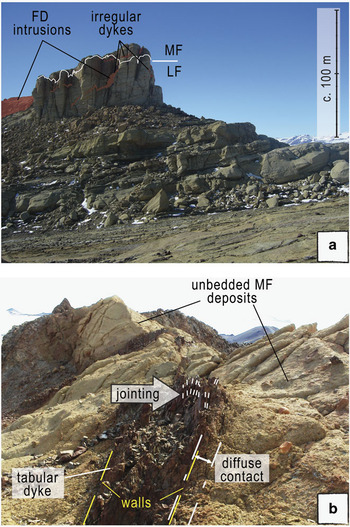
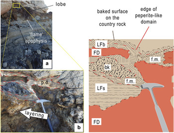
Dykes with the described geometries and other ‘swirly’ dolerite segments crop out in the Roscollyn Tor area, where magma intruded the Mawson-Lashly Formation contact (Fig. 12a). Swirly dykes are not systematically segmented and reach up to a few tens of metres long. They exhibit erratic changes of both dip and thickness along strike, and irregular contacts. Such features result in complex geometries: dykes emplaced at the top of the Lashly Formation and within the Mawson deposits (Figs 12 & 13) may divide into tabular (Fig. 12b) and lobate (Fig. 13a) portions and flame-like apophyses often protrude from their margins (Fig. 13a).
Ferrar Dolerite (FD) dykes propagated across the irregular contact (white line on Roscollyn Tor) between Lashly Formation (LF) and Mawson Formation (MF) deposits. a. Roscollyn Tor, view to south. This is the only location within NE1where the contact is exposed. b. Dolerite dykes on top of Roscollyn Tor exhibit closely spaced jointing; their contact with the Mawson volcaniclastic deposits is diffuse, view to east.

a. A dyke emplaced below the LF-MF contact shown in Fig. 12, walking pole used for scale is 135 cm long. b. A detail of the contact of the same intrusion, rock hammer for scale. Both photographs to north-east. The shaded pattern with the red dashed outline over photo b and labelled as p.d. highlights a peperite-like domain (see composite dykes section). The cartoon on the right illustrates some important features of such domain: LFb = baked Lashly Formation around a coherent FD intrusion. LFs = a sliver of Lashly Formation rock, with its sedimentary texture preserved, note that the line pattern used to represent the sliver does not represent its actual ‘layering’ (cf. photograph b). f.m. = fluidized material, i.e. sedimentary and igneous rock mingled together around the outer rim of the more coherent FD intrusion. bk = block of strongly baked sedimentary material.

The dolerite is overall chilled and lacks vesicles. Igneous margins locally grade into peperite-like domains, commonly surrounded by an alteration rim and articulated into zones where the igneous material solidified among either un-deformed slivers or folded (perhaps while liquefied) fragments of host sediment (Fig. 13b).
Composite dykes
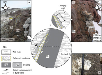
Some of the dolerite filled fractures are composed of distinct masses of dolerite representing multiple intrusions. Distinct intrusions are separated by chilled margins and, locally, slivers of thermally altered sandstone. Chilled margins (commonly less than ten centimetres thick) parallel the trend of the overall intrusion and its selvages, as do some of the slivers (Fig. 14).
a. A Ferrar Dolerite dyke resulted from two successive injections of magma (FD1, FD2). Some host material that was dragged in between the two pulses of magma and thermally deformed is now preserved as a 1–5 cm thick sliver of recrystallized sandstone. b. The hanging wall rock of this dyke exhibits kinks (view to east, pencil for scale), also due to propagation of, and thermal erosion by the magma. Enlargement cartoon beside the photo is rotated in order to have the same viewing direction. c. Slickenfibre of calcite formed on the footwall of the same intrusion, its location is also indicated on a. Relative motion of the dyke walls as shown in the cartoon at the centre of figure.

Sandstone occurs in thin recrystallized slivers, generally not thicker than five centimetres and deformed on the contact surface (Fig. 14a and cartoon in Fig. 14). The walls of most sheets are generally hard, smooth, planar surfaces, with the original sandstone fabric preserved and the dolerite chilled for only a few centimetres from the contact. Where composite dykes are exposed, their wall rocks and slivers are instead shaped into kinks and grooves (Fig. 14b), or scoured and mineralized with calcite slickenfibres (Fig. 14c), the significance of which is addressed later in this paper.
Damage induced in the host rocks
In the Beacon country rocks, where there are no intrusions, a regular ‘chessboard’ pattern defined by sub-orthogonal fractures with spacing on the order of a few tens of metres is observed. Around intrusions and between adjacent dykes such patterns become more densely spaced: dyke-parallel joints with maximum spacing of a few tens of centimetres occur adjacent to most intrusions (see Figs 6 & 11) and through-going vertical joints commonly extend up to a few metres beyond the tip of isolated segments and terminations of dolerite apophyses (as in Figs 10 & 11). With decreasing offset between adjacent tips, the interposed bridge of host rock is commonly rotated and even detached from its original position. In places, entire blocks of host rock are not only detached but also ‘sandwiched’ between dolerite slabs (see composite dykes section and Fig. 14). Bridges are frequently cut by fractures which interconnect opposite dyke-terminations (also in Fig. 11c). The denser the fracture network at the interaction zone and the less the offset/overlap between opposing dyke tips, the more likely a bridge is to contain crushed, fine breccia material, small and more or less thermally deformed slivers and chilled pods of intruded dolerite.
Such damage-zone relationships imply considerable fragmentation of weak country rock during dyke propagation, as also suggested by Brown et al. (Reference Brown, Kavanagh, Sparks, Tait and Field2007) for segmented kimberlite dykes in South Africa (cf. Table I and references therein, and see discussion in the next sections).
Intrusion geometries versus intrusive arrays
In the next section, field relationships, geometry and distribution of dykes at Allan Hills are considered relative to mechanical properties and natural anisotropies of their encasing rocks. All these features are used to constrain the structural and mechanical controls on the complex volcanological evolution of this part of the Ferrar province, and their tectonic significance.
Perhaps the key result of our analysis is that at depths<500 m, intrusions of any geometry were capable of opening and dilating cracks along bedding interfaces, thanks to low vertical stresses relative to internal overpressures of propagating magma.
Intrusion into an isotropic medium
Dykes of any orientation intruding the Beacon rocks at Allan Hills are generally segmented en echelon, with individual segments either irregular or zigzag in shape. Intrusive morphology (Fig. 3) is significantly influenced by structural properties of the country rocks. Irregular segment arrays and zigzag dyke-paths with no strong preferred orientation result from intrusion into isotropic materials. The shape of the intrusions reflects overall tensional hydrofracturing driven, at least in the horizontal plane, by internal magma pressure (see Tentler Reference Tentler2003). Effect of regional structural controls on magma propagation in anisotropic media is normally inferred from either consistent co-alignment of intrusions (such as clusters of dykes, individual intrusions, consistent stepping patterns of en echelon arrays and zigzag dykes, and even terminations of long apophyses, e.g. Kattenhorn & Watkeys Reference Kattenhorn and Watkeys1995) and fracture systems in the country rock (for instance, faults and regional joint sets). Despite their wide range of orientations and dips (Fig. 5), most irregular dolerite sheets at Allan Hills are coherently aligned, but the more consistent stepping patterns are observed along apophyses oblique to larger intrusions (Fig. 11a). Lithification and original sedimentary layering impart mechanical anisotropy to the Victoria Group, so that sills propagated at vertical discontinuities, but behaved isotropically in the palaeohorizontal plane. From this perspective, it seems that bedding contacts and fractures localized in the damage zones around dykes had exerted the main structural control on the emplacement of intrusions at Allan Hills, because no joint and/or fault systems of regional significance are known, and there is no evidence of tectonic control on the final geometry of the Ferrar inclined sheets we studied (Muirhead Reference Muirhead2008).
Intrusion into soft rock
The irregular crosscutting contact between the Beacon beds and the younger pile of Mawson Formation deposits in the Roscollyn Tor area marks a change from dolerite sheets with the geometries discussed above to a maze of dolerite, in places thoroughly intermixed as attenuated sheets and fragments with the volcaniclastic material. In a few localities the sheets are associated with zones where host material and fragments of chilled dolerite form chaotic mixtures that we interpret as peperites (Skilling et al. Reference Skilling, White and McPhie2002 and references therein). They resulted from intrusion of magma into unconsolidated, probably wet Mawson Formation volcaniclastic debris. Intrusion and subsequent cooling of magma were rapid, since the dolerite has a quench texture and the intrusions are dyke-like, albeit morphologically irregular. Evidence of low volume, volcaniclastic sediment fluidization and mingling with magma is localized between the flame-shaped apophyses.
Effects of interacting localized stresses
Other aspects of Ferrar intrusions e.g. dyke tip morphologies of contiguous segments, damage of the host rock and lateral transgressions of shallowly dipping dykes into sills, reflect the parameters that influenced magma propagation and emplacement at Allan Hills. Tip geometries are commonly used as proxies of local strain conditions during dyke formation (Pollard et al. Reference Pollard, Muller and Dockstader1975). Such strain conditions control the arrest of individual dykes or the interaction and coalescence of contiguous ones via variably shaped ‘connectors’ (Rickwood Reference Rickwood1990), bridges and damage zones (Weinberger et al. Reference Weinberger, Lyakhovsky, Baer and Agnon2000). Co-linear segments forming an intrusion either have composite curved offset tips, or coalesce laterally and exhibit a complex damage zone. Linear tapering tips associated with isolated intrusions represent the arrest of pure tensional fractures orthogonal to the direction of least compressive stress. Blunt and bifurcated ends result from lateral transfer of tip dilation along host rock inhomogeneities, at a high angle to the dyke trend, or from erosion of the host rock by irregular, pulsatory magma flow at the tip. This is evident from most terminations of adjacent dykes (Fig. 11). When magma-filled cracks approach each other, their associated stresses prevail over the remote stress field and cause contemporaneous rotation of the local principal stresses by lateral shear and new fracturing of the encasing rock (e.g. Delaney et al. Reference Delaney, Pollard, Ziony and Mckee1986). Curved tip geometries are a direct consequence of localized stress rotation (see Weinberger et al. Reference Weinberger, Lyakhovsky, Baer and Agnon2000 and references therein), whereas complex terminations comprising horns and more or less brecciated bridges result from the deflection of magma into the newly formed joints of the damage zone (Anderson Reference Anderson1951).
Size and morphology of the damage zones around dykes vary with the stage of evolution of the magma-filled cracks. Where the internal magma pressure was enough to promote both vertical and lateral coalescence of adjacent dykes, dolerite intrusions exhibit steps and stubs connecting co-linear segments and the surrounding host rock can be intensely fractured or partially crushed. This is a result of contemporaneous ascent and lateral propagation of the magma-filled cracks, with progressive fracturing, crushing, rotation and/or detachment of the bridge of country rock (Kattenhorn & Watkeys Reference Kattenhorn and Watkeys1995). Slivers of sandstone ‘floating’ within the dolerite or breccia material record the completion of this process.
Transgressive sills, multiple intrusions and related host rock deformation
Previous (Grapes et al. Reference Grapes, Reid and McPherson1974) and new (this study) field observations at Allan Hills reveal a number of interconnected sills and shallowly dipping sheets cutting the Victoria Group units (e.g. Figs 4 & 7). Alternation of inclined sheets with sills characterizes both dyke sets, although the majority of intrusions of shallower dip belong to AI (histogram c in Fig. 5). At one site (Fig. 7a), the pile of sedimentary rock folded and cracked, destabilized around the thin tip of an advancing sill. Other features locally observed are: bands of dolerite bounded by chilled margins overlapping one another, corrugated surfaces and recrystallized slivers of sandstone entrained between dolerite of successive injections, and slickensides formed at sheet walls (Fig. 14).
The deflection of a dyke along bedding to form a sill represents, fundamentally, the re-orientation of the principal stresses around a crack tip during magma ascent in the (vertically anisotropic) layered sequence. Taisne & Jaupart (Reference Taisne and Jaupart2009) demonstrate that coupled lithostatic stress and hydrostatic density gradients in magma rising through a dyke can prime a cycle of pressure (and stress) accumulation and release within, and around the tip as it approaches a low-density layer. Fresh magma delivered to the upper tip of the intrusion causes the internal overpressure to increase, and reach a maximum at the boundary with the overlying low-density layer. Such repeated local stress variations (stress cycling) are accentuated with diminishing depth and can be influenced by variable properties of the encasing rocks. At the interface with a low-density layer, rising magma either overshoots vertically or is deflected laterally along bedding. Lateral deflection depends on the depth of emplacement, being favoured where magma-driven deformation can be accommodated via a deformable free surface, or bedding plane (Galland et al. Reference Galland, Planke, Neumann and Malthe-Sørenssen2009, Taisne & Jaupart Reference Taisne and Jaupart2009). Such stress cycling is partly controlled by the hydrostatic equilibrium between magmatic pressure and vertical loading above the head of the intrusion (Lister & Kerr Reference Lister and Kerr1991), and partly by density and rigidity contrasts within the pile of intruded sedimentary rock (e.g. Goulty Reference Goulty2005, Kavanagh et al. Reference Kavanagh, Menand and Sparks2006, Taisne & Jaupart Reference Taisne and Jaupart2009).
The Victoria Group sequence is well exposed at Allan Hills (Grapes et al. Reference Grapes, Reid and McPherson1974), but in area NE1 its thickness is rather modest (< 500 m) due to erosion prior to magmatism (Elliot & Larsen Reference Elliot and Larsen1993, Reubi et al. Reference Reubi, Ross and White2005).
An important inference from the above is that intrusions of any geometry were capable of overcoming the tensile strength of the bedding interfaces, dilating them because the vertical stresses above the propagating magma would be low relative to internal magma overpressures.
In addition to recording stress cycles affecting the local sedimentary sequence, the described features represent various phases in formation of a transgressive intrusion. We picture it as a fivefold process: 1) sill injection, inflation and thickening along bedding, 2) inclined sheet propagation, 3) initiation of new sills by dilation of the next suitable flat lying horizon, 4) prolonged magma flow or re-injection, with associated thermo-mechanical deformation of the host rocks, and 5) eruption at the surface.
The first three stages draw fundamentally on previous studies of how stacks of sills propagate within sedimentary basins (see Menand Reference Menand2008, Thomson & Schofield Reference Thomson and Schofield2008 and references therein), and together they comprise a process similar to that outlined for the formation of saucer-shaped sills (for example in the South African Karoo basin, see Polteau et al. Reference Polteau, Mazzini, Galland, Planke and Malthe-Sørenssen2008 for a review):
1) A sill first spreads laterally along bedding and thickens, which destabilizes its surrounding sedimentary pile by forced folding.
2) The sheet grows by fracturing and widening of country rock cracks at the tip of the intrusion, which eventually leads to upward breakouts of magma. The point of transition between these two initial stages depends mainly on variation in host rock properties with depth through the sedimentary pile. Fracturing and faulting at the tip of a sill-type intrusion is favoured at greater depths, where low cohesive strength along bedding planes impedes flexural-slip folding.
3) Beginning during evolution of a dyke-sill transgression but extending over longer timescales, new sill sheets develop. This occurs as magma continuously enters the same fractures, or is intermittently injected (re-injection) into them, and breaks out through sill-tip cracks, then propagating along a new zone of bedding plane weakness (Fig. 14).
4) At greater depths and with longer heating, the wall rock responds ductilely to the progressive intrusion of magma. When a new pulse of magma arrives, softened wall rock allows displacement of partly solidified dolerite (FD1 in Fig. 14) with respect to its country rock footwall. At Allan Hills, successive injections strayed from the original dyke planes, injecting either the same fractures or ones of similar trends and only slightly offset from the planes of the earlier structures. This resulted in slivers of sedimentary rock being captured in the igneous, hot material, and recrystallized and deformed by thermal contact with it. Lastly, striations commonly associated with slickenfibres of calcite and slickensides were preserved along shallowly dipping sheets interconnecting sills at different stratigraphic levels. Such striations are indicative of non-ductile grooving between the dolerite and the wall rock during re-injection.
5) Finally, the large blocks of country rock that display vertical bedding in area NW (aerial photograph in Fig. 1) show that the rocks that roofed over the propagating intrusions may have been broken and tilted above the décollement surface of fluid magma, with lavas erupting at the palaeosurface (e.g. White et al. Reference White, Bryan, Ross, Self and Thordarson2009) but no longer preserved at Allan Hills.
Volcanological history
Structure of Allan Hills: summary
Ferrar Dolerite intrusions mapped at Allan Hills include sills and a total of 93 inclined dolerite sheets. Inclined sheets with unpredictable orientations and geometry add up to a minimum cumulative length of c. 64.5 km. Using the same mean width (0.75 m) calculated for the intrusions in area NE1, the cumulative width of the 93 inclined sheets in the nunatak is 69.75 m. Ferrar Dolerite sills prevail in the western and eastern arms of the nunatak. Large sill outcrops occupy most of the northern periphery of the NW area, and blocks of country rock are locally engulfed within the dolerite masses (Fig. 1). Networks of thin sills and dolerite sheets predominate in area NE but there is no evidence for significant breakup of their roof of country rocks (Fig. 4).
Except for a few roughly west-striking dykes intruding the volcaniclastic deposits and the Weller Coal Measures in the southernmost area S, the inclined dolerite sheets exposed at Allan Hills define consistent NW–SE structural trends (Fig. 1). The most significant cluster of dykes is exposed in area NE1, whereas only minor and poorly clustered arrays of dolerite intrusions crop out in the other three areas. Ferrar Dolerite sheets within area NE1 can be separated into the overall parallel dyke swarm AI and the ‘radial’ array AII (Fig. 5). The former dyke set comprises both coherent and segmented sub-parallel dolerite sheets. AII dykes are highly segmented and become increasingly asymmetric and thick towards their area of common intersection, which is located c. 300 m west of Roscollyn Tor (Fig. 5). The younger dyke set post-dates AI intrusions and, in the Roscollyn Tor area, the Mawson Formation deposits (Figs 6 & 12). Field relationships indicate a complex succession of multiple intrusions, intersection of crack-paths and interaction between adjacent magma-filled cracks.
Magmatism
In the following interpretation, the magmatic source of each portion of the local plumbing system, unless otherwise stated, is considered to be a ‘sill’. This is reasonable inference because sills are the most voluminous components, and represent the dominant mode of magma propagation and emplacement within Beacon rocks along the Transantarctic Mountains (Gunn & Warren Reference Gunn and Warren1962, Marsh Reference Marsh2004, Leat Reference Leat2008). In the field area, transgressive intrusions observed in area NE1, and sills and interconnections among inclined and flat-lying intrusions that are exposed in the eastern arm of the nunatak indicate that dykes were sourced from sills that range from a few metres to tens of metres in scale. Locally in the Allan Hills area, the sills propagated very close to, or reached the surface. There, magma interaction and heating of pore fluids in the host rock resulted in hydromagmatic explosions that dismembered the roof rocks, thus generating the overturned rafts observed in the NW area (cf. White et al. Reference White, Bryan, Ross, Self and Thordarson2009 for nearby Coombs Hills).
Interconnected igneous sheets and sills represent the preferred mode of magma transport across layered sedimentary sequences (see Thomson & Schofield Reference Thomson and Schofield2008 and references therein), and their importance in LIP formation was also recently highlighted (see Cartwright & Hansen Reference Cartwright and Hansen2006, Leat Reference Leat2008). A network of interconnected shallowly dipping intrusions must be actively injected during the magmatism and extend all the way to the surface in order to feed flood basalt eruptions (Spera Reference Spera1980, Cartwright & Hansen Reference Cartwright and Hansen2006, Polteau et al. Reference Polteau, Mazzini, Galland, Planke and Malthe-Sørenssen2008). The intrusive network at Allan Hills exhibits characteristics consistent with such a plumbing system.
The main factors that we consider here to explain and tentatively locate the origin of such intrusive patterns at Allan Hills are the geometry and average trends of the exposed arrays, and the local, generally homogeneous, north-eastward dip of Beacon layering (Fig. 5).
The dip of Victoria Group layering at Allan Hills is anomalous, because Beacon rocks of south Victoria Land are known to dip gently in a west-south-west direction (i.e. inland from the Ross Sea coastline, see Gunn & Warren Reference Gunn and Warren1962). A large sill-type source advancing at shallow depth would be consistent with both the anomalous north-eastward dip and the step-wise geometry of many of the observed AI dolerite sheets, and similarly striking dykes in area NW. The sill would have propagated north-eastward from south-west of Allan Hills nunatak, accounting for the north-west trend and south-west dip direction of the intrusions in area NE1. Assuming a gradual decrease in sill thickness from its centre to the periphery, this sill would also account for the regionally anomalous north-east bedding tilt or, more likely, monoclinal folding of the sedimentary pile. In this scenario, the few dolerite sheets identified in area S would have either bypassed or cut through the suite of phreatomagmatic (maar-diatreme) structures identified by White and McClintock (Reference White and McClintock2001) and Ross et al. (Reference Ross, White and McClintock2008) at both Allan Hills and its neighbouring nunatak, Coombs Hills.
As for the radiating dyke swarm AII, some of its longest intrusions thicken and become increasingly asymmetric towards their area of intersection, indicating a common source. Similar patterns are widely documented in the literature (e.g. at Spanish Peaks, Colorado, see Delaney & Pollard Reference Delaney and Pollard1981 and references therein; Hawaii and Galapagos, Walker Reference Walker1999 and references therein). Such a source, as reconstructed using the method of the ‘maximum intersections’ (Fig. 5, after Ancochea et al. Reference Ancochea, Brändle, Huertas, Hernán and Herrera2008), was located c. 300 m west of Roscollyn Tor.
Radiating swarms are commonly generated from tensile stresses surrounding inflating ‘chambers’ and cylindrical conduits, and both the AII dyke array and its segments resemble structural trends of intrusive networks found in Iceland (e.g. Annels Reference Annels1967). Explaining the radiating geometry of the AII dykes still remains problematic, because evidence on the nature of the magmatic source that fed them is lacking, although it may be hidden below the substantial areas of scree at Allan Hills.
The existing volcaniclastic deposits and AII Ferrar dykes may be the marginal remnants of one of a number of small, locally overlapping, phreatomagmatic tuff-ring complexes in Allan Hills (White et al. Reference White, Bryan, Ross, Self and Thordarson2009), a large relative of which is exposed in the neighbouring nunatak Coombs Hills (White & McClintock Reference White and McClintock2001). Intrusion of magma under relatively isotropic stress conditions, produced from either forceful injection of AI dolerite sheets, or point-inflation of a relatively shallow sill into a number of narrow fractures carrying magma into a maar-type edifice may be better explanations for the weakly developed radiating pattern of segmented dykes seen here. The shallower structures exposed on Roscollyn Tor, which are also the most segmented and irregular, may record waning of the intrusion into unconsolidated, recently emplaced Mawson deposits (Fig. 13).
Conclusions
Allan Hills (south Victoria Land, Antarctica) offers one of a few high-quality exposures of shallow intrusive complexes formed during the evolution of the Ferrar LIP. Insights into the mechanics of intrusion and the volcanological history of the nunatak are based on photogeological analysis and field observations of intrusion geometries and relationships. The nunatak exposes interconnections of transgressive sheets. We interpret tilted blocks of the youngest Beacon strata, enclosed within dolerite, as indicating that the sheets locally breached the surface via the breakup of shallow sill roof rock. The dykes are assigned to two generations: AI, formed as a swarm of parallel dykes and transgressive intrusions extending from a sill, and AII, developed as a radiating swarm associated with a phreatomagmatic eruption site.
We find no evidence at the scale of the nunatak that dyke propagation was affected by extensional rift tectonism. Structural controls could have been exerted by basement structures, but these are not known in south Victoria Land nor observed at Allan Hills.
Dyke geometries and relationships with the host rocks are consistent with a process of intrusion dominated by magmatic pressures. Magma created its own set of fractures both across the isotropically-behaving sedimentary rocks of the Victoria Group and their overlying Mawson volcaniclastic deposits, unconsolidated at the time of intrusion.
An important implication of these results is that networks of transgressive sills and shallowly dipping dykes may represent the preferred mode of magma transport across the Ferrar LIP. We suspect that a shallow level of intrusion reflected the same tectonic stress regime as deeper rocks, but that decreased confining pressures amplified the response of the intrusions to it. This would imply that similar processes operate at depth, requiring a neutral tectonic regime, rather than extensional as envisaged for the Ferrar LIP, in order to be structurally consistent.
Acknowledgements
We acknowledge the University of Otago and the New Zealand Division of Science for postgraduate funding to G. Airoldi, Antarctica NZ and Helicopters NZ for support of field activities, and Antarctic Science for funding attendance to the XXVII IAVCEI General Assembly (Iceland, August 2008). I. Schipper, C. Timms and V. Toy are thanked for help reviewing drafts of the manuscript. D. H. Elliot and an anonymous reviewer are thanked for helpful comments on a previous version of the manuscript. O. Galland and T. Menand are thanked for constructive reviews.