1 Introduction
In many applications, for example spray cooling (Bolle & Moureau Reference Bolle and Moureau1982; Kim Reference Kim2007; Ebadian & Lin Reference Ebadian and Lin2011) or in internal combustion engines (Naber & Reitz Reference Naber and Reitz1988), the interaction of a spray with a hot wall can be observed. For an isothermal drop impact onto a dry solid substrate the outcome depends mainly on the impact velocity, drop diameter, substrate morphology and wettability and liquid properties (Rioboo, Tropea & Marengo Reference Rioboo, Tropea and Marengo2001). Comprehensive reviews of these phenomena can be found in Yarin (Reference Yarin2006), Marengo et al. (Reference Marengo, Antonini, Roisman and Tropea2011), Yarin, Roisman & Tropea (Reference Yarin, Roisman and Tropea2017) and elsewhere. By varying the surface temperature, the phenomenon of drop impact can change significantly and different thermodynamic phenomena can be observed, namely drop evaporation, Marangoni related effects, nucleate boiling, transition boiling, atomisation and film boiling (Bernardin, Stebbins & Mudawar Reference Bernardin, Stebbins and Mudawar1997). A comprehensive review on the drop impact phenomena onto hot surfaces can be found in Quéré (Reference Quéré2013), Liang & Mudawar (Reference Liang and Mudawar2017) and regime maps for various surface temperatures and impact parameters can be found in Bernardin et al. (Reference Bernardin, Stebbins and Mudawar1997), Tran et al. (Reference Tran, Staat, Prosperetti, Sun and Lohse2012) and Bertola (Reference Bertola2015).
Nucleate boiling (Chandra & Avedisian Reference Chandra and Avedisian1991; Breitenbach, Roisman & Tropea Reference Breitenbach, Roisman and Tropea2017a ) is characterised by the generation of expanding bubbles at the substrate, leading to a significant increase of the heat flux density (Chen, Chow & Navedo Reference Chen, Chow and Navedo2002).
The Leidenfrost temperature (Leidenfrost Reference Leidenfrost1966), which is the minimum temperature for the film boiling regime, is influenced by various parameters, for instance the surface and liquid properties (Bernardin, Stebbins & Mudawar Reference Bernardin, Stebbins and Mudawar1996; Bernardin & Mudawar Reference Bernardin and Mudawar1999; Zhong & Guo Reference Zhong and Guo2017) or the impact parameters (Shirota et al. Reference Shirota, van Limbeek, Sun, Prosperetti and Lohse2016). Based on rising pressure at the liquid–solid interface for an impinging drop, it has recently been shown that the Leidenfrost temperature increases when the drop impact velocity increases (Testa & Nicotra Reference Testa and Nicotra1986; Celata et al. Reference Celata, Cumo, Mariani and Zummo2006). A analytic model for the drop and spray impact in the film boiling regime has been recently obtained in Breitenbach, Roisman & Tropea (Reference Breitenbach, Roisman and Tropea2017b ).
The surface temperature influences the characteristic size of secondary droplets and the splashing threshold (Cossali, Marengo & Santini Reference Cossali, Marengo and Santini2005; Moreira et al. Reference Moreira, Moita, Cossali, Marengo and Santini2007). Drop impact onto a hot surface has been further studied for high-velocity impacts (Mehdizadeh & Chandra Reference Mehdizadeh and Chandra2006), viscoelastic liquids and polymer additives (Bertola Reference Bertola2004, Reference Bertola2009) and micro-structured surfaces (Tran et al. Reference Tran, Staat, Susarrey-Arce, Foertsch, van Houselt, Gardeniers, Prosperetti, Lohse and Sun2013).
In the present study the phenomenon of a single drop impact onto a hot surface is studied with the aim of characterising the drop breakup mechanism at a substrate temperature and at impact parameters yielding conditions between nucleate and film boiling, designated here as thermal atomisation. This study includes observations of a single drop impact using a high-speed video system and identification of different thermodynamic and hydrodynamic outcomes.
Two dimensionless numbers, the Reynolds number and the Weber number, are often used to describe the outcome of drop impact, even in the cases when boiling significantly influences the flow in the spreading drop. They are defined by
 $$\begin{eqnarray}Re=\frac{D_{0}U_{0}}{\unicode[STIX]{x1D708}},\quad We=\frac{\unicode[STIX]{x1D70C}D_{0}U_{0}^{2}}{\unicode[STIX]{x1D70E}},\end{eqnarray}$$
where
 $D_{0}$
and
 $U_{0}$
are the diameter and velocity of the impinging drop, and
 $\unicode[STIX]{x1D708}$
,
 $\unicode[STIX]{x1D70C}$
and
 $\unicode[STIX]{x1D70E}$
are the kinematic viscosity, density and surface tension of the liquid. Moreover, in many instances the Weber number alone is used, resulting from the assumption that for impact onto very hot surfaces the contact between the liquid and solid regions is absent and the viscous effects are negligibly small. However, the present experiments indicate that if the impact velocity is high enough, part of the solid surface is wetted. This phenomenon leads to strong local overheating of the liquid and intensive evaporation at the contact line, fast irregular dewetting, breakup and levitation. It is shown that the Weber number is therefore not the relevant parameter for description of the drop impact outcome under these conditions. In this study the main dimensionless parameters determining this regime and defining the atomisation threshold are analysed. Finally a dimensionless regime map of drop impact is presented.
2 Experimental method
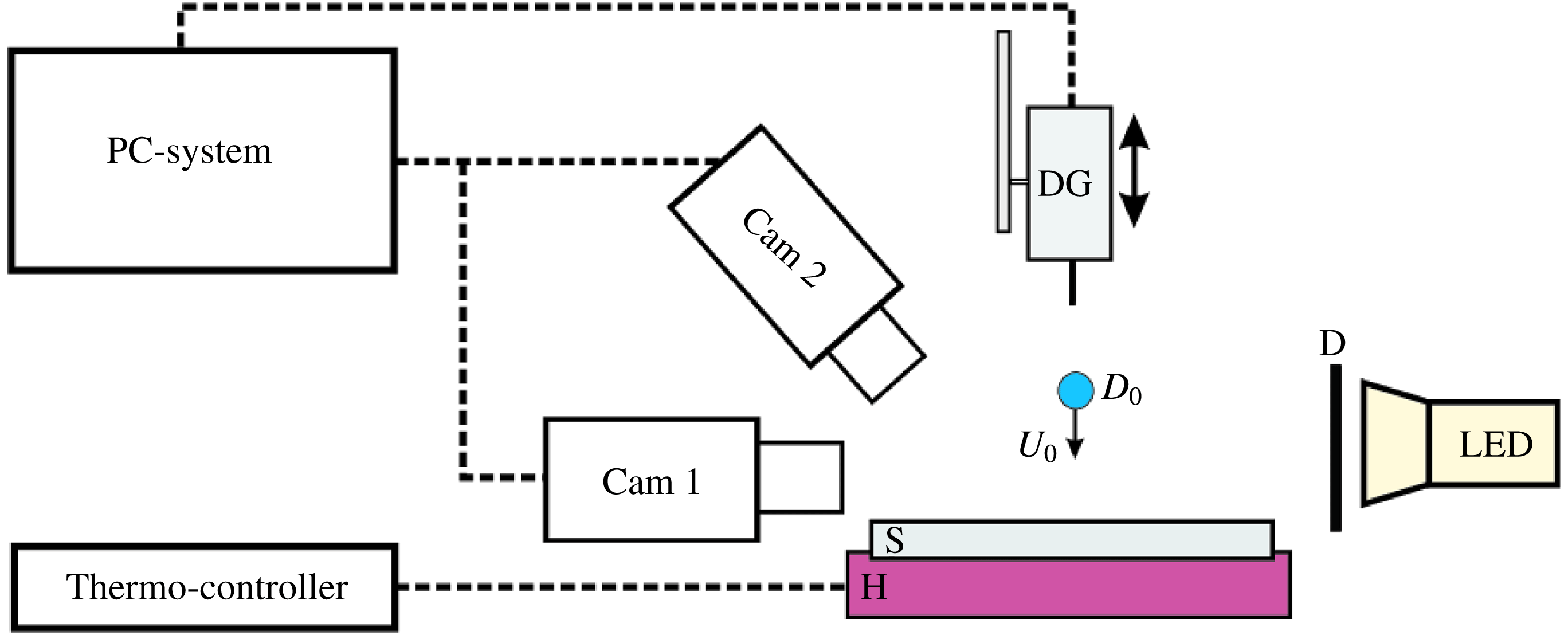
Experimental set-up: heating system (H and S) controlled by a thermo-controller, drop generation unit (DG), an illumination system (LED) with a diffuser plate (D), a computer control system (PC-system) and two synchronous CMOS high-speed cameras (Cam 1 and Cam 2).

2.1 Experimental set-up
The experimental set-up shown in figure 1 comprises a controlled heating system (H and S) for an exchangeable substrate, the drop generator unit (DG), the illumination system (LED) with a diffuser plate (D), the PC-system control unit and two synchronous CMOS high-speed video cameras (Cam 1 and Cam 2) with a maximum resolution of
 $1280~\text{pixel}\times 800~\text{pixel}$
at 6242 f.p.s. to record side-view and upper-view images of drop impact.
The heating system consists of an aluminium substrate (S) embedded in a heated copper cylinder (H). A thermally isolated 250 W cartridge heater is placed inside the cylinder. The impact surface of the aluminium substrate (EN AW 7075) is mirror polished to achieve an average surface roughness of
 $R_{a}\approx 0.05~\unicode[STIX]{x03BC}\text{m}$
, measured by an atomic force microscopy. The temperature of the impact surface before impact is controlled by a thermo-controller together with a Type-K thermocouple placed 0.5 mm below the central drop impact point on the substrate. The initial surface temperature can be varied between
 $T_{0}=50\,^{\circ }\text{C}$
and
 $400\,^{\circ }\text{C}$
.
The drop is produced in the drop generation unit (DG) with a blunt hypodermic needle and a piezoelectric micro-pump, which supplies the fluid trough the needle until a droplet detaches due to gravity. The drop generator and its position is controlled by the computer. By changing the size of the blunt hypodermic needle and the position of the needle above the surface, different drop diameters
 $D_{0}=1.6{-}3.5~\text{mm}$
and impact velocities
 $U_{0}=0.3{-}3.0~\text{m}~\text{s}^{-1}$
can be realised. Smaller drops,
 $D_{0}=0.1{-}0.8~\text{mm}$
with impact velocities
 $U_{0}=4.0{-}12.0~\text{m}~\text{s}^{-1}$
are generated by a monodisperse piezoelectric drop generator. Double distilled water (density
 $\unicode[STIX]{x1D70C}_{l}=998~\text{kg}~\text{m}^{-3}$
, kinematic viscosity
 $\unicode[STIX]{x1D708}_{l}=10^{-6}~\text{m}^{2}~\text{s}^{-1}$
and surface tension
 $\unicode[STIX]{x1D70E}_{l}=72.75\times 10^{-3}~\text{N}~\text{m}^{-1}$
) is used in the experiments. The initial drop temperature is almost constant
 $T_{l}\approx 20\,^{\circ }\text{C}$
for all the performed experiments and controlled with a thermocouple within the fluid.
2.2 Observations of different outcomes of drop impact
Observed microscopic thermodynamic phenomena: convection boiling, nucleate boiling, transition boiling and film boiling.

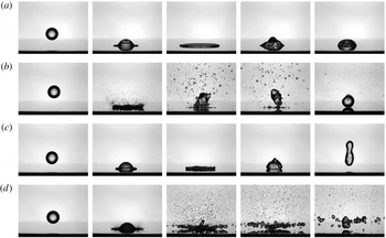
Drop impact of different observed hydrodynamic impact regimes: (a) drop deposition,
 $U_{0}=1.47~\text{m}~\text{s}^{-1}$
,
 $T_{0}=120\,^{\circ }\text{C}$
, (b) drop dancing,
 $U_{0}=0.71~\text{m}~\text{s}^{-1}$
,
 $T_{0}=180\,^{\circ }\text{C}$
, (c) drop rebound,
 $U_{0}=0.71~\text{m}~\text{s}^{-1}$
,
 $T_{0}=280\,^{\circ }\text{C}$
and (d) drop thermal atomisation,
 $U_{0}=1.71~\text{m}~\text{s}^{-1}$
,
 $T_{0}=260\,^{\circ }\text{C}$
. In all the examples the initial drop diameter is
 $D_{0}=2.15{-}2.17~\text{mm}$
.

Various thermodynamic conditions (figure 2) are observed for different surface temperatures: convection boiling, nucleate boiling, transition boiling and film boiling. The complete boiling process is transient and not only controlled by the initial surface temperature
 $T_{0}$
. The evaporation behaviour of a single drop can change in time due to the change of drop size or surface temperature.
Observations of the drop impact lead to a classification according to different impact outcomes. In figure 3 various hydrodynamic impact regimes are pictured: (a) drop deposition, (b) drop dancing, (c) drop rebound and (d) drop thermal atomisation. In the present study examining non-isothermal drop impact, hydrodynamic forces (inertia, viscous and surface tension forces) leading to the different impact outcomes are accompanied by thermodynamic phenomena. In the drop deposition regime no rebound is observed and the drop wets the surface for the entire duration of evaporation. After the impact the droplet begins to evaporate due to convection or nucleate boiling until it is totally evaporated. The drop dancing regime is a transient regime between the drop deposition and drop rebound regime; the drop appears to dance on the hot surface, explained by the numerous vapour bubbles and liquid layers frequently growing and collapsing. This regime is mainly characterised by transition boiling. The bubbles appear on a substrate within the spreading drop a short time after the first instant of contact. In this regime, the liquid near the substrate is initially superheated and bubbles appear in the solid surface after a certain waiting time
 $t_{w}$
(Carey Reference Carey1992). In our experiments the waiting time is very short. It is much smaller than the temporal resolution of the high-speed camera,
 $t_{w}<100~\unicode[STIX]{x03BC}\text{s}$
and definitely is much shorter than the typical time of drop spreading. Accompanying the vapour bubbles are numerous massive secondary droplets, generated when the bubbles burst through the liquid/gas interface above the drop. After a significant drop mass loss due to evaporation and generation of secondary droplets, the residual liquid mass often recoils.
In the drop rebound regime occurring at higher surface temperatures, the entire drop bounces directly after the drop spreading and receding; this impact regime is mainly caused by a vapour layer at the substrate surface (film boiling phenomena), since it reduces energy dissipation. Furthermore, the drop rebound can be seen with some secondary droplets and bubbles within the drop, caused by partial wetting during drop spreading and receding (advance state of transition boiling phenomena). All these thermodynamic phenomena and impact regimes have been observed before and discussed in the literature (Bernardin et al. Reference Bernardin, Stebbins and Mudawar1997; Tran et al. Reference Tran, Staat, Prosperetti, Sun and Lohse2012; Bertola Reference Bertola2015).
The present study is focused on the mechanisms of drop thermal atomisation, leading to the generation of many fine secondary drops formed from the drop spreading lamella, and to the formation of a number of larger drops formed as a results of rim breakup. A typical example of this thermal atomisation regime is shown in figure 3(d).
3 Thermal atomisation threshold: not described by the Weber number
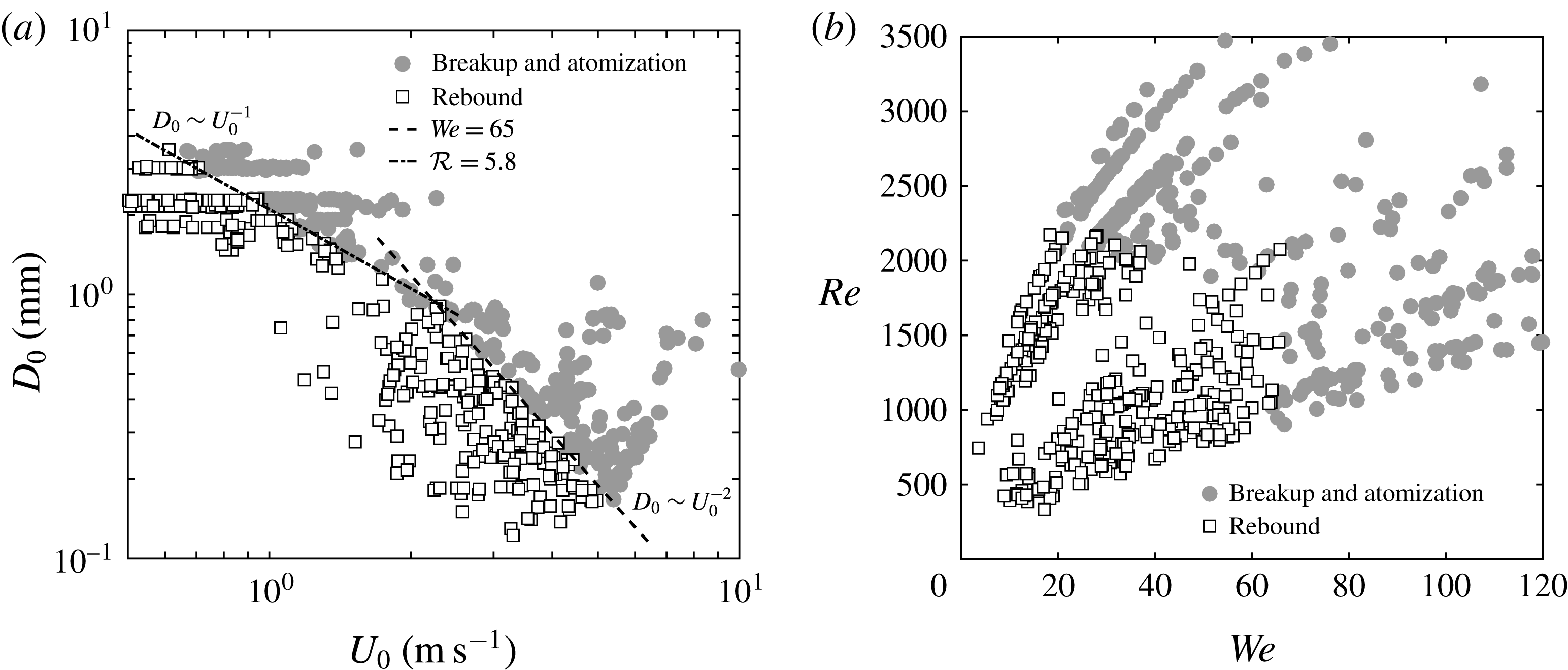
Map of drop impact parameters leading to drop thermal atomisation or drop rebound. The wall temperature is the same for all the experiments,
 $T_{0}=250\,^{\circ }\text{C}$
. The same data are plotted in the form
 $D_{0}$
versus
 $U_{0}$
(a) and in the form
 $Re$
versus
 $We$
(b).

In order to identify the parameters or dimensionless groups governing the thermal atomisation process, a number of experiments have been performed with the same initial wall temperature
 $T_{0}=250\,^{\circ }\text{C}$
but different drop impact velocities and diameters. The experimental data are shown in figure 4. For impact velocities
 $U_{0}<2~\text{m}~\text{s}^{-1}$
the critical drop diameter corresponding to the drop atomisation is approximately
 $D_{atom}\sim U_{0}^{-1}$
. For this threshold the Weber number is not relevant, since inertial forces are very small. This is a very important result, since the Weber number is used rather widely for describing various phenomena arising from drop impact onto a very hot substrate. One of the assumptions leading to the extensive use of the Weber number is that intensive evaporation near the hot substrate prevents direct contact and wetting and therefore the effect of the liquid viscosity is negligibly small. It appears from our results however, that this assumption is not universal.
For larger impact velocities
 $U_{0}>2~\text{m}~\text{s}^{-1}$
where inertial forces begin to dominate, the critical diameter for atomisation scales well with
 $D_{atom}\sim U_{0}^{-2}$
. This result indicates that a critical Weber number can be used for modelling the drop breakup threshold in this regime, but only in this regime.
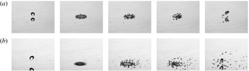
Inertia induced rim breakup for high Weber number and small drop diameters: (a) receding breakup,
 $D_{0}=340~\unicode[STIX]{x03BC}\text{m}$
,
 $U_{0}=4.0~\text{m}~\text{s}^{-1}$
,
 $T_{0}=220\,^{\circ }\text{C}$
, and (b) prompt splash combined with receding breakup,
 $D_{0}=360~\unicode[STIX]{x03BC}\text{m}$
,
 $U_{0}=6.8~\text{m}~\text{s}^{-1}$
,
 $T_{0}=250\,^{\circ }\text{C}$
. Thermal effects do not influence the breakup.

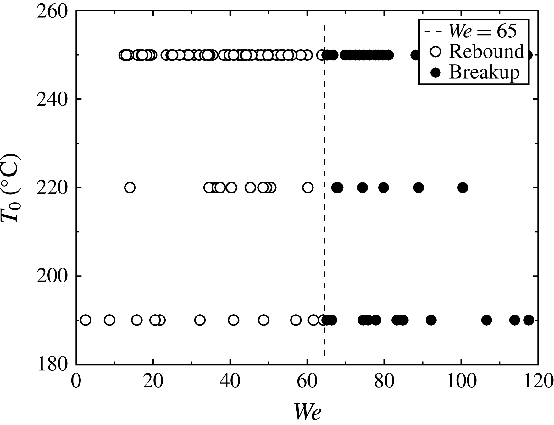
In summary, the Weber number, which is defined as the ratio of the inertial forces to surface tension, does not account for thermal effects. This parameter can therefore describe only drop breakup governed by inertia. To examine this hypothesis a breakup map has been plotted for drops of diameter much smaller than 1 mm. According to the results shown in figure 4, these drops atomise at a definite Weber number. They breakup due to the rim instabilities during the drop spreading or receding, since the rim receding velocity is higher than the velocity of dewetting. In this regime a prompt splash and a receding breakup can be observed, as shown in figure 5. The breakup mechanism is very similar to drop receding breakup on hydrophobic substrates (Rioboo et al.
Reference Rioboo, Tropea and Marengo2001), which is often observed on cold substrates. The breakup threshold in these experiments is
 $We=65$
. This value is similar to the breakup threshold of
 $We=53$
in Lv et al. (Reference Lv, Hao, Zhang and He2016) or
 $We=90$
in Tsai et al. (Reference Tsai, Pacheco, Pirat, Lefferts and Lohse2009) for impacts onto dry, superhydrophobic substrates at room temperature. Furthermore, for a drop impact onto a hot surface far above the Leidenfrost temperature, Wachters & Westerling (Reference Wachters and Westerling1966) identify a critical threshold
 $We=80$
for a breakup governed by inertia. Since there is no wetting of the spreading droplet with the surface in the film boiling regime, the spreading conditions are similar to those of superhydrophobic substrates.
The regime map, shown in figure 6, demonstrates that the threshold Weber number for such small drops does not depend on the initial target temperature. This type of drop breakup regime is not considered as thermal drop atomisation in this study.
This difference of the inertial breakup (occurring at the Weber numbers above a certain critical
 $We$
value) and thermal atomisation (at the Reynolds numbers exceeding a certain critical
 $Re$
value), can be clearly seen on figure 4(b), where the same experimental data are presented as a function of Reynolds number and Weber number. For the specific conditions of the experimental plotted in figure 6, the critical Reynolds number is approximately
 $Re\approx 2000$
.
Our experiments unequivocally show that the Weber number is not an appropriate parameter for quantitatively describing the thermal atomisation threshold. The Reynolds number alone also does not capture the thermal effects involved in the impact. In order to predict the thermal atomisation threshold the physical processes accompanying thermal atomisation have to be considered in more detail and alternative dimensionless numbers for the thermal atomisation threshold have to be developed. First suggestions for such new dimensionless numbers will be discussed in the following sections.
Breakup regime map for various surface temperatures and Weber numbers for drop diameters smaller than 1 mm. The breakup is inertia induced and therefore independent of the surface temperature.

Top view of the drop impact onto a hot surface in the thermal atomisation regime: the impact parameters are
 $D_{0}=2.22~\text{mm}$
,
 $U_{0}=2.47~\text{m}~\text{s}^{-1}$
and the wall temperature
 $T=330\,^{\circ }\text{C}$
.

4 Substrate wetting and irregular dewetting
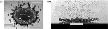
Drop spreading and breakup in the atomisation regime. In (a) (view of the spreading drop from above) the wetted part of the substrate, where the lamella is in contact with the wall, is the dark region, whereas the light grey region corresponds to the levitated part of the lamella. The wetted part in contact with the wall, and the levitated part of the lamella are clearly seen in the side view (b).

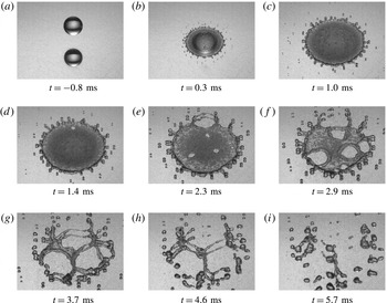
A typical scenario of drop thermal atomisation is shown in the top view time sequence in figure 7. In all the observed cases an intensive thermal atomisation is accompanied by the lamella breakup. The spreading lamella breaks up by an expansion of several holes, nucleated at several points on the lamella periphery (where the lamella is thinnest). The expansion of the holes is caused mainly by capillary forces (Taylor Reference Taylor1959), assisted also by the aerodynamic forces associated with the vapour flow from below, induced by intensive evaporation.
Different regions of the lamella are defined in figure 8. For this sketch a drop image at the instant
 $t=2.3~\text{ms}$
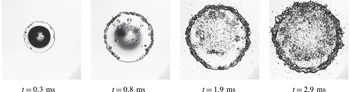
in figure 7 is used. Drop spreading in the thermal atomisation regime is always accompanied by partial lamella detachment and its breakup. Lamella detachment leads to the separation of the lamella region into a wetted lamella region and a free levitated lamella. The wetted region of the spreading lamella is seen as a matt, dark part of the image. This optical effect is caused not only by the contact with the substrate but also by the appearance of a large number of small bubbles, nucleated at the wetted substrate surface. The nucleation of such bubbles and their expansion can be observed on a transparent target (see figure 9).
There is no doubt that the intensive heterogeneous nucleation observed from above as a dark region is a wetted region of the substrate. Such phenomena has been observed in Chaze et al. (Reference Chaze, Castanet, Cabalina, Maillet, Pierson and Lemoine2017) using infrared thermography. They have detected a drastic drop of the temperature and an increase of the heat flux density at the substrate surface on the wetted region, which indicates contact between the superheated liquid and the wall.
Heterogeneous nucleation and fast bubble growth during drop spreading on sapphire glass at an initial temperature
 $T=190\,^{\circ }\text{C}$
.

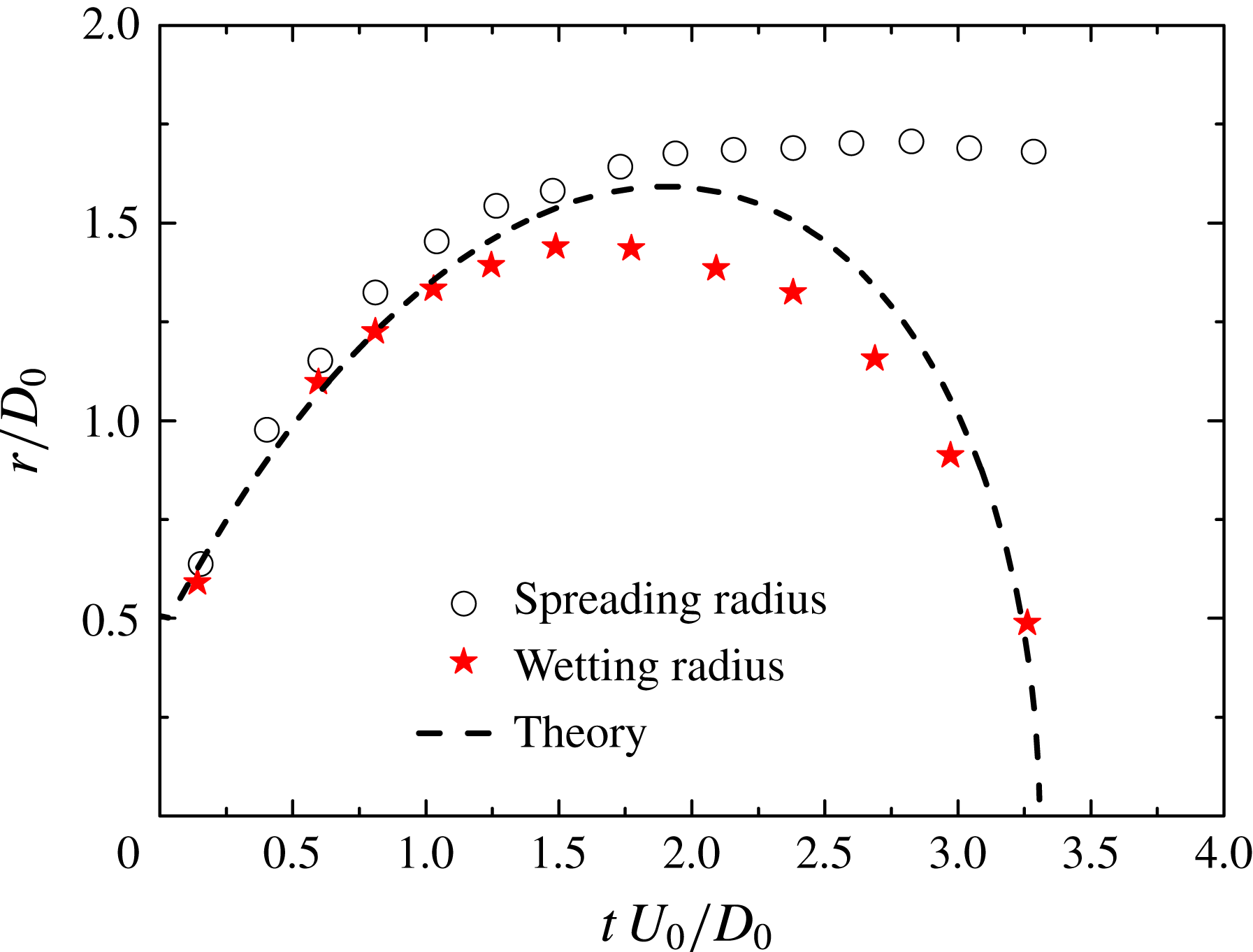
Evolution of the average dimensionless drop spreading radius and of the radius of the wetted region in thermal atomisation regime. The impact parameters are the same as in figure 8:
 $D_{0}=2.22~\text{mm}$
,
 $U_{0}=2.47~\text{m}~\text{s}^{-1}$
and the wall temperature
 $T=330\,^{\circ }\text{C}$
. The dimensionless radius of the wetted spot is also compared with the theoretically predicted values from (5.5).

The evolution of the radius of the wetted spot can be very roughly estimated measuring the profile of the dark region. The results of these measurements are shown in figure 10. The radius initially increases. This is caused by the increase of the region of high pressure of the order of
 $p\sim \unicode[STIX]{x1D70C}_{l}U_{0}^{2}$
, produced by the impacting drop (Roisman Reference Roisman2009). This pressure rapidly reduces in time and at large times after impact, quickly approaches the outer pressure. Starting at these times the dewetting process is possible. The radius of the dark region during spreading is always slightly smaller than the spreading radius. This is explained by the delay time for bubble creation during heterogeneous nucleation (Carey Reference Carey1992).
5 Mechanisms leading to the lamella levitation. Contact time of an impacting drop
In the wetted region a viscous boundary layer develops, leading to the thickening of the lamella. When the thickness of the viscous boundary layer equals the thickness of the lamella, the spreading is strongly damped by viscosity (Roisman Reference Roisman2009). If the Reynolds number
 $Re=U_{0}D_{0}/\unicode[STIX]{x1D708}_{0}$
is defined on the basis of the viscosity at room temperature
 $\unicode[STIX]{x1D708}_{0}$
, the residual lamella thickness
 $h_{res}$
in the wetted region is estimated from Roisman (Reference Roisman2009)
 $$\begin{eqnarray}h_{res}\approx 0.79D_{0}(\unicode[STIX]{x1D708}/\unicode[STIX]{x1D708}_{0})^{2/5}Re^{-2/5},\end{eqnarray}$$
where
 $\unicode[STIX]{x1D708}$
is the kinematic viscosity of the heated liquid. The thickness of thermal boundary layer can be estimated as
 $h_{t}\approx k\sqrt{\unicode[STIX]{x1D6FC}_{l}t}$
, where
 $k$
is a dimensionless constant of order unity. At the initial stages the heat flux from the hot substrate goes mainly into the heating of the liquid in the expanding thermal boundary layer. At some time instant the thermal boundary layer reaches the free surface of the lamella, leading to its fast heating and initiation of intensive evaporation. The heat flux in the liquid region quickly reduces, since the heat exchange between the free surface of the lamella with the surrounding gas is relatively small. In this region most of the heat from the substrate goes towards the liquid evaporation. The bubbles grow much faster, coalesce, forming a continuous vapour layer between the spreading lamella and the substrate. As a result the outer part of the lamella levitates.
As can be seen in figure 8(a), the boundary between the central wetted region and the levitated region of the lamella is not smooth. This shape is a result of the unstable evaporation of a superheated liquid in the lamella, similar to corresponding observations in Khavari et al. (Reference Khavari, Sun, Lohse and Tran2015) and van Limbeek et al. (Reference van Limbeek, Shirota, Sleutel, Sun, Prosperetti and Lohse2016).
The substrate temperature at the dewetting front approaches the saturation temperature since it is in contact with the moving evaporating liquid/vapour interface. Therefore, the heat flux in this region is maximal. This effect leads to very intensive evaporation, leading to the generation of small bubbles in the lamella and a subsequent spray of fine secondary droplets. This phenomena has been observed in Cossali et al. (Reference Cossali, Marengo and Santini2005).
The phenomenon of liquid film detachment and levitation on a very hot surface is not new. Expansion of a wetted region during stationary liquid jet impact onto very hot surfaces has been observed in Piggott, White & Duffey (Reference Piggott, White and Duffey1976), Hammad, Mitsutake & Monde (Reference Hammad, Mitsutake and Monde2004) and Karwa et al. (Reference Karwa, Gambaryan-Roisman, Stephan and Tropea2011). In these experiments the expansion of the wetting front has been observed with a relatively slow velocity of millimetres per seconds. The propagation is caused by the local substrate cooling in the wetted region. Aktershev & Ovchinnikov (Reference Aktershev and Ovchinnikov2011) studied experimentally and modelled theoretically intensive dewetting of a heated substrate caused by the dynamic effects associated with the pressure in a bubble created on the substrate due to evaporation.
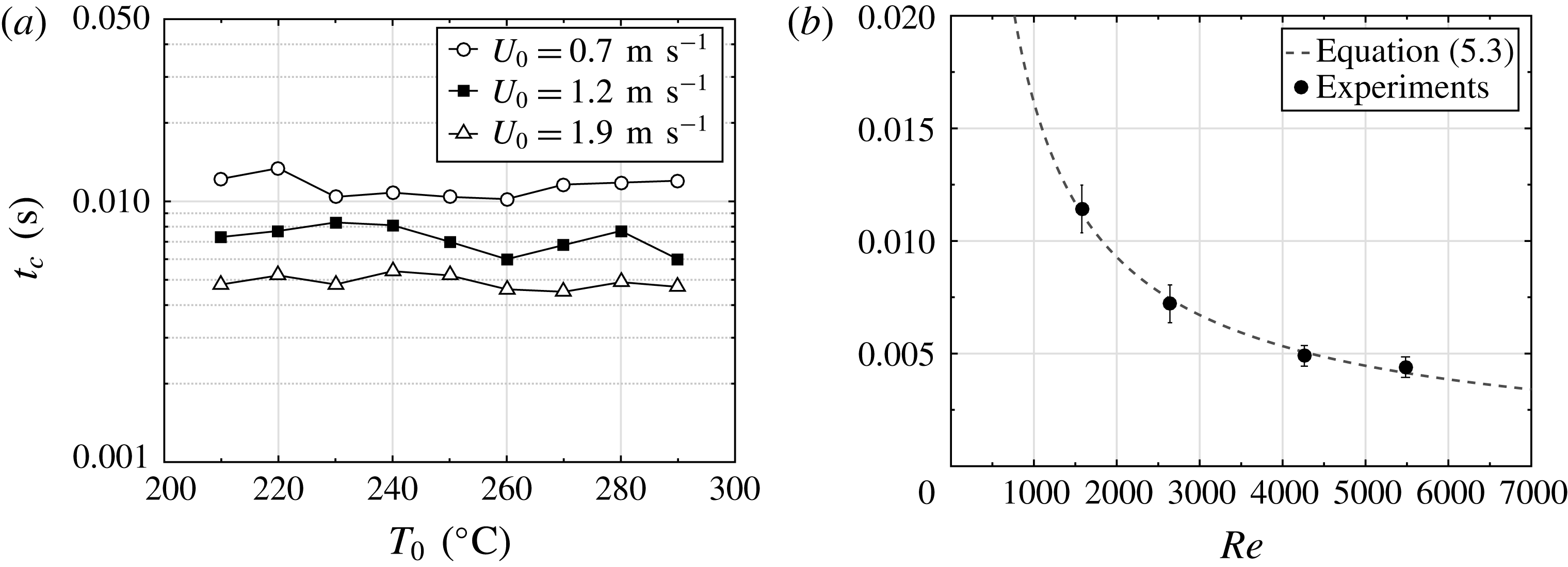
To characterise the velocity of the dewetting in the present experiments, the contact time of a spreading drop is measured. The contact time of the drop on the substrate corresponds to the instant when the entire lamella detaches from the wall surface. As shown in figure 11, the contact time does not depend strongly on the initial wall temperature, but is determined by the Reynolds number
 $Re=D_{0}U_{0}/\unicode[STIX]{x1D708}_{0}$
, where
 $\unicode[STIX]{x1D708}_{0}$
is the kinematic viscosity of the liquid at room temperature. The best fit of the experimental data yields
 $t_{c}\sim Re^{-0.79}$
for the drop contact time.
Contact times
 $t_{c}$
for drops impacting a wall for atomisation and rebound regimes: (a) for various initial wall temperatures and (b) averaged values and standard deviation from experiments with almost the same impact parameters as a function of the impact Reynolds number in comparison with theoretical prediction (5.3) with
 $k=1.0$
(dashed line). Drop diameter is
 $D_{0}=2.2~\text{mm}$
. Reynolds number is based on the liquid viscosity at the room temperature.

This time differs from the typical time of capillary oscillations,
 $t_{\unicode[STIX]{x1D70E}}\sim \sqrt{D_{0}^{3}\unicode[STIX]{x1D70C}/\unicode[STIX]{x1D70E}}$
, which does not depend on the impact velocity and is often used for the description of the time of drop deformation caused by collision (Willis & Orme Reference Willis and Orme2000).
Since the lamella levitation is associated with the growth of the thermal boundary layer within the lamella, the entire lamella has to be detached when the thermal boundary layer reaches the top of the free surface of the lamella. Equating the residual lamella thickness with the thickness of thermal boundary layer
 $$\begin{eqnarray}h_{res}\sim h_{t},\end{eqnarray}$$
yields a theoretical estimation of the contact time
 $$\begin{eqnarray}t_{c}=\frac{0.6D_{0}^{2}}{k^{2}\unicode[STIX]{x1D6FC}_{l}Re^{4/5}}\frac{\unicode[STIX]{x1D708}^{4/5}}{\unicode[STIX]{x1D708}_{0}^{4/5}}.\end{eqnarray}$$
The value of
 $\unicode[STIX]{x1D708}^{4/5}/\unicode[STIX]{x1D6FC}_{l}\approx 20.0~\text{s}^{1/5}~\text{m}^{-2/5}$
depends only very weakly on the temperature of superheated water. The power of the Reynolds number
 $-4/5$
estimated in (5.3), is very close to the experimentally determined power,
 $-0.79$
. The predictions for the contact time are compared with the experimental data in figure 11(b) for
 $k=1.0$
. The fact that the
 $k$
-value is comparable with unity confirms the main physical assumptions used above to explain the mechanism of drop detachment.
The evolution of the wetting radius can be predicted if the evolution of the lamella thickness is known. It is known that in the case of high Reynolds, high Weber number impacts the dimensionless lamella thickness is universal (Roisman, Berberović & Tropea Reference Roisman, Berberović and Tropea2009). The observed evolution of the lamella profile can be approximated by
 $$\begin{eqnarray}\bar{h}_{l}=\frac{0.39}{(\bar{t}+0.25)^{2}}\exp \left[-\frac{2.34\bar{r}^{2}}{(\bar{t}+0.25)^{2}}\right],\quad \bar{h}_{l}\equiv \frac{h_{l}}{D_{0}},\quad \bar{r}\equiv \frac{r}{D_{0}},\quad \bar{t}\equiv \frac{tU_{0}}{D_{0}}.\end{eqnarray}$$
Equating the lamella thickness with the thickness of the thermal boundary layer yields an expression for the radius of the wetted spot
 $$\begin{eqnarray}\bar{R}_{wet}\approx 0.65(\bar{t}+0.25)\sqrt{\ln \left[\frac{\sqrt{\bar{t}_{c}}(\bar{t}_{c}+0.25)^{2}}{\sqrt{\bar{t}}(\bar{t}+0.25)^{2}}\right]}.\end{eqnarray}$$
The predicted value of the dimensionless wetted radius
 $\bar{R}_{wet}$
is compared in figure 10. The agreement between theory and experiment is rather good, which further confirms the hypothesis about the mechanism of dewetting governed by the propagation of the thermal boundary layer and its interaction with the free surface of the spreading lamella.
6 Parameters influencing the atomisation threshold and dimensionless regime map
A dimensionless number, characterising the thermal atomisation regime, can be defined as the ratio of the contact time to the typical drop spreading time,
 ${\mathcal{R}}\sim t_{c}U_{0}/D_{0}$
, with
 $t_{c}$
defined in (5.3)
 $$\begin{eqnarray}{\mathcal{R}}=PrRe_{H}^{1/5},\quad Re_{H}\equiv \frac{D_{0}U_{0}}{\unicode[STIX]{x1D708}},\quad Pr\equiv \frac{\unicode[STIX]{x1D708}}{\unicode[STIX]{x1D6FC}_{l}},\end{eqnarray}$$
where the Reynolds number
 $Re_{H}$
is based on the viscosity of the hot liquid and
 $Pr$
is the Prandtl number. As previously shown in figure 4, the threshold for thermal atomisation is
 ${\mathcal{R}}\approx 5.8$
for
 $T_{0}=250\,^{\circ }\text{C}$
. Since for superheated water the variation of the term
 $\unicode[STIX]{x1D708}^{4/5}/\unicode[STIX]{x1D6FC}_{l}$
is weak, the dimensionless number can be scaled as
 ${\mathcal{R}}\sim D_{0}^{1/5}U_{0}^{1/5}$
.
The regime maps existing in the literature are influenced significantly by the substrate properties. Comparison of the maps in Tran et al. (Reference Tran, Staat, Prosperetti, Sun and Lohse2012) and Bertola (Reference Bertola2015) leads to the conclusion that the temperature alone cannot describe the threshold, even for the same liquid on different surfaces. The main parameter governing the phenomenon of drop vaporisation and possible atomisation is the characteristic heat flux. At the contact line, i.e. the region of intensive evaporation, the substrate temperature is close to the saturation temperature. The heat flux between the wall and the spreading drop occurs mainly in the expanding thermal boundary layers, whose thickness increases as the square root of time. The solution for heat transfer in such systems is well known (Roisman Reference Roisman2010; Breitenbach et al.
Reference Breitenbach, Roisman and Tropea2017a
). Heat conduction in the solid wall is described by an expanding thermal boundary layer near the wall surface. The characteristic heat flux associated with vaporisation is expressed for the typical time of drop impact
 $t_{i}=D_{0}/U_{0}$
in the form
 $$\begin{eqnarray}\langle \dot{q}\rangle =\frac{e_{w}(T_{0}-T_{sat})}{\sqrt{t_{i}}}=\frac{e_{w}(T_{0}-T_{sat})\sqrt{U_{0}}}{\sqrt{D_{0}}}.\end{eqnarray}$$
The ratio of the drop impact velocity and the velocity associated with the drop vaporisation is
 $$\begin{eqnarray}{\mathcal{U}}=\frac{\langle \dot{q}\rangle }{\unicode[STIX]{x1D70C}_{v}LU_{0}}=\frac{e_{w}(T_{0}-T_{sat})}{\unicode[STIX]{x1D70C}_{v}L\sqrt{D_{0}U_{0}}},\end{eqnarray}$$
where
 $L$
is the latent heat of evaporation and
 $\unicode[STIX]{x1D70C}_{v}$
is the density of the water vapour.
Regime map for the dimensionless contact time
 ${\mathcal{R}}$
and dimensionless heat flux
 ${\mathcal{U}}$
of a drop.

A final regime map for different initial values of the dimensionless heat flux
 ${\mathcal{U}}$
and the dimensionless contact time
 ${\mathcal{R}}$
is shown in figure 12. It should be noted that experimental data for drop atomisation from Bertola (Reference Bertola2015) also coincide with the results presented in figure 12.
Two branches of the atomisation threshold can be identified in figure 12. They are illustrated by the curves threshold I and threshold II. At lower substrate temperatures (lower values of
 ${\mathcal{U}}$
) the threshold impact velocity, leading to thermal atomisation, reduces if the wall temperature increases. This is an expected result. The characteristic time of lamella breakup
 $t_{break}$
reduces at higher substrate temperatures. The curve threshold I corresponds to the situation when
 $t_{break}$
is equal to the contact time. The impact velocity corresponding to the threshold II surprisingly increases when the substrate temperature is higher. This transition is probably associated with such intensive evaporation that the dynamic pressure in the vapour flow is comparable with the dynamic pressure produced by drop impact. Such vapour flow therefore prevents the expansion of the wetted spot even at the initial stages of drop impact and spreading.
7 Conclusion
This study describes different regimes and outcomes of drop impact considering the interaction of different physical processes. One of these processes is thermal dewetting of the substrate. The dewetting front is characterised by the intensive drop evaporation, initiation of the lamella levitation, and disintegration. This is the reason why this regime is called here thermal atomisation.
A typical time of propagation of the thermal boundary layer in the lamella is estimated. It is shown that this time is very close to the observed contact times of the spreading lamella before its detachment and disintegration.
In many previous attempts to describe and model outcomes of drop impact onto very hot substrates, the Weber number has been used to account for the impact parameters of the drop. In this study the threshold for thermal atomisation for a given wall temperature is determined experimentally. It is scaled well as
 $D_{0}\sim U_{0}^{-1}$
. Therefore the Weber number is not a relevant parameter for description of the threshold for thermal atomisation. A dimensionless drop contact time
 ${\mathcal{R}}$
is estimated and introduced as a relevant threshold value bounding thermal atomisation and rebound regimes. Additionally, a dimensionless heat flux
 ${\mathcal{U}}$
is introduced, which serves as a second dimensionless parameter governing the intensity of drop evaporation leading to thermal atomisation. Finally a dimensionless regime map for drop impact is plotted in terms
 ${\mathcal{R}}{-}{\mathcal{U}}$
.
Acknowledgements
This research was supported by the German Research Foundation (Deutsche Forschungsgemeinschaft) in the framework of the Collaborative Research Center SFB-TRR 75, subproject C4.