I. INTRODUCTION
In recent years, energy and environmental problems such as energy crisis and global warming have become hot topics in various fields. As one of the solutions, a green-eco technology using highly performed eco-electronics and green energy harvesting has been proposed to stop these extraordinary geographical phenomena [Reference Kawasaki1]. Traditionally, radio-frequency (RF) and microwave technologies have been used for wireless communication and sensor network systems. Since the new usage of microwave technology opens a new market, the energy harvesting and microwave power transmission (MPT) as one of wireless power transmission (WPT) technologies have been rapidly developed.
The high-power MPT system is indispensable for DC power supply in an aerospace sensor network. Although power consumption of a wireless part is low enough when applying low-power solution such as ZigBee, that of the sensor unit is still relatively high. This is because, for data reliability and accuracy, much high data-sampling speed needs for the aerospace and aircraft applications. The MPT is a promising technology to be integrated with the wireless sensor network system for complement of the battery. To realize the integration, wireless information/communication, and power transmission (WiCoPT) and wireless sensor and energy transfer (WiSEnT) technologies have been proposed [Reference Kawasaki1].
On the aerospace wireless sensor network, communication dependability should be high as that is on the wired. The wireless sensor network technology has been already developed such as the structural health monitoring system in the ground applications [Reference Salas, Focke, Herrmann and Lang2–Reference Teo, Lim, Sutomo, Tan, Gopalakrishnan and Singh5]. Scheduling for optimal communication is also published for the wireless sensor networks system [Reference Moges and Robertazzi6]. Conventional wired sensor network system [Reference Karolys and GenKuong7, Reference Senesky, Jamshidi, Cheng and Pisano8] is mainly used in the aircraft application. In recent years, the wireless sensor network in the aerospace [Reference Wagner and Barton9–Reference Zhao12] has been discussed as one of the solutions to overcome the maintenance and weight issue [Reference Zheng and Armstrong13, Reference Vladimirova14]. However, removal of the last line of an electric power cable has not been discussed deeply.
To realize the aerospace sensor network system with the MPT function, feasibility of the coexistence between the high-power MPT and the wireless communication should be studied. In general, transmitting power level is restricted by regulations for human safety and avoiding interference to other RF systems. Further, feasibility of the coexistence between them under the MPT situation has not been discussed deeply so far. However, in a limited or unmanned area inside the rockets or vehicles, the human safety need not be considered. Obeying RF power level regulations [15], the MPT system with wireless communication equipment have been proposed [Reference Oruganti, Heo, Ma and Bien16, Reference Ichihara, Mitani and Shinohara17].
For test to the aerospace sensor network system proposed in the paper, a reusable vehicle test (RVT) developed by the Japan Aerospace eXploration Agancy (JAXA) is planned to use. The wireless system for health and safety monitoring inside the RVT is strongly demanded. For this purpose, temperature, pressure, and hydrogen gas sensors were selected in order to replace the conventional wired ones. Our final goal is to replace about 100 channel sensors. The sensors are distributed all over inside the RVT. Therefore, the sensors are requested to be possible data communication without considering location. Non-line-of-sight propagation is assumed because aeroshell covers the frame of the RVT. The RVT is about 3 m tall. For the reliability of the system, fundamental data for precision control and sampling time are also requested. From this point, scheduling of operation for WiCoPT/WiSEnT should be organized.
In this paper, the novel wireless sensor network system with compatibility of the high-power MPT for the aerospace application is proposed. For the coexistence, time- and frequency-division operations are applied. The wireless communication system in 2.4 or 5.8 GHz band and the MPT system in 5.8 GHz band are integrated. As the first stage of the system realization, the proposed system is evaluated in an anechoic chamber. In the following sections, system design, microwave components, measurement results, and comparison of coexistence operations are discussed.
II. DESIGN OF THE PROPOSED SENSOR NETWORK SYSTEM
A) The category of WPT
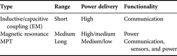
The WPT technology is categorized into three types [Reference Xie, Shi, Hou and Lou18]: magnetic resonant [Reference Salas, Focke, Herrmann and Lang2, Reference Baek, Ahn, Kim, Choi and Kwak19], inductive/capacitive (or electromagnetic (EM)) coupling [Reference Mayordomo, Drager, Alayon and Bernhard20–Reference Xue, Cheng and Je22], and EM radiation [Reference Li, Han, Ogai, Sawada and Wang23, Reference Georgiadis, Collado and Niotaki24]. Table 1 summarizes the features of each WPT type. The EM radiation type using microwaves is especially called the MPT. The MPT type has advantages of long-distance transmission and low sensitivity for displacement [Reference Arbizzani, Prete, Masotti and Costanzo25], comparing with other two WPT methods. On the other hand, disadvantage of the MPT is relatively low efficiency in energy/power transmission such as with micro-watt or several milli-watt order power [Reference Popovic, Falkenstein, Costinett and Zane26, Reference Visser and Vullers27].
The type of WPT by power delivery principles.

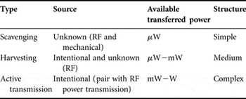
The MPT systems using microwave or millimeter wave bands are categorized into three types, according to power levels. Table 2 summarizes them. The first is the scavenging type, for targeting very weak power densities and wide bandwidth such as for wide coverage services. The second is an energy harvester type, for targeting weak power densities such as for narrow coverage area services. The RF energy harvesting [Reference Yano28, Reference Guenda, Collado, Carvalho, Georgiadis and Niotaki29] is also subject to handle with the micro-watt order power level. The RF energy-harvesting systems enable us utilize television broadcasting wave [Reference Lim, Lee and Poh30–Reference Ishizaki, Ikeda, Yoshida, Maeda, Kuroda and Mizuno32]. In order to realize the compact RF energy harvester, the ultra-low-power consumption transceiver by a Monolithic Microwave Integrated Circuit (MMIC) [Reference Vidojkovic33] has been proposed. Other energy sources such as heat and vibration can also be harvested. The third is the active energy/power transmission system [Reference Kawasaki34] that intentionally sends the RF energy to the specific position such as those used in the space solar power station and wireless charging of electric vehicles.
The type of MPT by available transferred power.

B) Time- or frequency-division operations for coexistence
Location of the sensor node is allowed to be flexible due to the nature of wireless. Therefore, the MPT system can be compatible with wireless communication and is indispensable for the wireless sensor network system. For the reliable compatibility, time- and frequency-division operations for both the MPT and the wireless communication were proposed and evaluated in this paper. For the coexistence with the wireless communication, the MPT system might not be activated when the same operating frequency is used. This is because high-power MPT signal interrupts communication signals in the receiver. Therefore, the operation either in the frequency division or in the time division should be selected to coexist with the MPT as well as the wireless communication. The time-division operation is reliable for minimizing mutual interference. However, from the view-point of the data transmission efficiency, the time-division operation is less effective since MPT and the data communication time is shared in series comparing with the continuous frequency-division operation. The frequency-division operation takes great advantage of much energy transfer capability comparing with the time-division one. Disadvantage of the frequency-division operation is to increase circuit complexity since multi-frequency RF units are required.
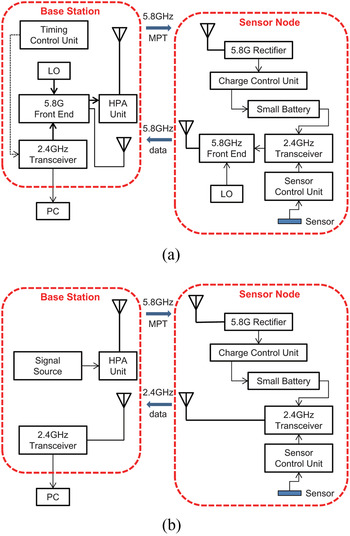
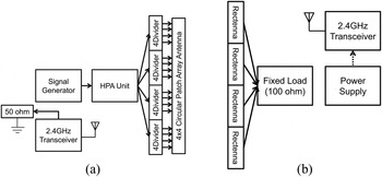
Block diagrams of the proposed sensor network system are shown in Fig. 1. The high-power MPT system operating at 5.8 GHz was equipped for both operations. Meanwhile, the wireless communication system operates in the 5.8 GHz band and the 2.4 GHz band for time- and frequency-division operations, respectively. Timeslots for the MPT as well as for the communication are completely divided and alternately allowed to transmit/receive the RF signal as for the time-division operation. On the other hand, the frequency-division operation uses over two frequency bands simultaneously for the MPT and for the communication. The maximum bit rate of the 2.4 GHz band communication was settled with 250 kbps. Table 3 shows the link budget of the 5.8 GHz band wireless communication. Margin of 30.1 dBm is calculated using the data sheet value of receiver sensitivity of −97 dBm. The rectified DC power in the sensor node is used for power supply of the transceiver and the sensor control unit through battery-charging. Data from the sensors for temperature, pressure, and gas leakages are transmitted by the wireless communication system and are displayed on the PC connected to the base station.
The system block diagrams of the proposed sensor network system compatible with MPT: (a) the time-division operation and (b) the frequency-division operation.

Link budget of the 5.8 GHz band wireless communication.

* Feed loss of 3.6 dB is included.
C) Requirement for the MPT system
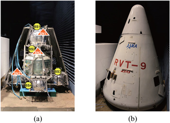
To design the MPT system, the optimum input power level to the rectifier as well as the output power of the high power amplifier (HPA) should be determined. From the preliminary experimental results, it was found that the propagation loss at 5.8 GHz inside the RVT varied from 36.6 to 58.0 dB by changing the position of the sensor node [Reference Tashiro35]. In the measurement, to evaluate the freedom possibility of sensor node or base station placement, the base station and sensor node is placed at different positions, such as top and bottom sides of the RVT, the innermost position shown in Fig. 2 [Reference Tashiro35]. Considering the measurement condition and result, we defined the propagation loss inside the RVT for calculation of the power diagram is 50.0 dB. Main obstacles in the RVT are hydrogen, nitrogen, and oxygen tanks. Aluminum frame is also scatterer. Strong multipass is assumed because the RVT is closed by the aeroshell made by carbon–fiber–reinforced plastic. In the design process, propagation loss of 50 dB and antenna gains of 6.7 dB for 2 × 2 array and 18.9 dB for 4 × 4 array are fixed as the constant. The power consumption of the sensor node is assumed to be 100 mW from the system requirement. Considering the margin with 20%, the output power of the rectifier is settled with 120 mW. The estimated output power for the HPA of the MPT transmitter is 47.0 dBm when the rectifier RF–DC conversion efficiency of 50% is assumed in the design. Table 4 summarizes the calculation results.
Measurement condition of the propagation loss using the RVT [Reference Tashiro35]: (a) locations of the base station and the sensor node and (b) after attachment of the aeroshell.

Power diagram of the proposed high power MPT system.

* Pointing loss of 1.3 dB is included.
† Output power per one rectifier.
D) Scheduling of the time-division operation
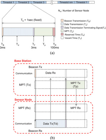
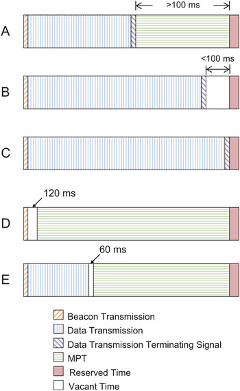
The time-division operation requires a timing control function for scheduling of the MPT and the data transmission communication. Figure 3 shows the scheduling for the time-division operation. The divided timeslot is assigned to each sensor node. Time rates of the MPT and the communication dynamically change depending on data volume. The reserved time is specially assigned for gas leakage sensor since the fastest alert of a couple of seconds is required for the gas leakage detection. The sensor data transmission starts after the beacon signal from the base station is received as shown in Fig. 3(b). When all data are sent, the terminating signal is replied to the base station. After the terminating signal is received at the base station, the MPT system turns on immediately. Figure 4 shows variation of the timeslot assignment depending on the communication situations. If the timeslot for the MPT is remained over 100 ms after data transmission, then the MPT system turns on as shown in the situation A in Fig. 4. When the timeslot for MPT is <100 ms, the MPT system does not turn on as shown in the situation B. The sensor data cannot be sent within the timeslot as shown in the situation C, while the data transmission is suspended until the next timeslot remaining the reserved time. In case the signal from the sensor node is not received as shown in the situation D, the MPT system turns on after 120 ms waiting time. If the data transmission is disconnected and the terminating signal is not received indicated in the situation E, then the MPT system is switched on after 60 ms vacant time.
The scheduling for the time-division operation: (a) the total sequence and (b) the details in one timeslot.

Variations of the timeslot assignment depending on the communication situations.

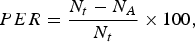
To evaluate the communication quality, received signal strength indicator (RSSI) and packet error rate (PER) were adopted. The RSSI and the PER are displayed on a control PC monitor from the RSSI packet frame. The PER is defined as
 $$PER = \displaystyle{{N_t - N_A} \over {N_t}} \times 100,$$
where N t and N A are the theoretical number of received packets and the actual number of received packets, respectively. The number of packet is counted by the sequence ID of each packet. Accuracy of the PER is 1% since only the newest 100 packets are used for calculation. On the other hand, the output DC power of the rectifier and the drain current of the HPA unit were measured for characteristics of the MPT system.
E) Experimental setup for evaluation
1) The 5.8 GHZ MPT system
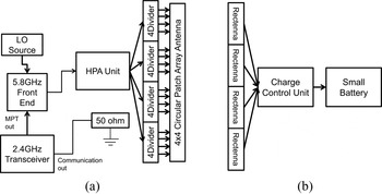
Characteristics of components in the proposed 5.8 GHz MPT system are evaluated independently with respect to the total system evaluation. Figure 5 shows a block diagram of the MPT system evaluation. A signal source of 5.8 GHz MPT is generated by the 2.4 GHz band base station. The 2.42 GHz CW signal is generated by the base station, and then the signal is up-converted to 5.8 GHz. In this experiment, the communication output is terminated with the 50-Ω load. The HPA unit shown in Section IIIA) was used. A 5.8 GHz band 4 × 4 circular patch array antenna with four dividers is used as a MPT antenna. In the receiver, four rectennas have the function to convert energy from RF to DC. The generated DC power is used for battery charging through a charge control unit. Instead of the battery and the charge control unit, the constant load resistance is used in the basic characteristics measurement.
The block diagram of the MPT system evaluation: (a) in the base station and (b) in the sensor node.

2) The time-division operation
To demonstrate coexistence operation, using the 5.8 GHz band wireless communication system and the 5.8 GHz MPT system, the time-division coexistence experiment is carried out. The scheduling of the time sequence in the time division was shown in Fig. 3. The number of sensor nodes in the proposed system is four. Each timeslot with 1 s is assigned for an individual sensor node. When only one sensor node is used in the experiment,
 $$T_{d2} = T_{d3} = T_{d4} = 0,$$
 $$T_{P2} = T_{P3} = T_{P4},$$
where T dn is the data transmission time, T Pn is the MPT time in the nth sensor node timeslot. The units of T dn and T Pn are millisecond.
Duty cycles for the wireless communication and the MPT are defined as follows:
 $$\eqalign{DR_{Com.} = & \displaystyle{{T_{d1} + T_{d2} + T_{d3} + T_{d4}} \over {4000}} = \displaystyle{{T_{d1}} \over {4000}},}$$
 $$\eqalign{DR_{MPT} = & \displaystyle{{T_{P1} + T_{P2} + T_{P3} + T_{P4}} \over {4000}} = \displaystyle{{T_{P1} + 3T_{P2}} \over {4000}},}$$
where DR Com . is the duty cycle for the wireless communication time in the four timeslot, DR MPT is the duty cycle for the MPT time in the four timeslots.
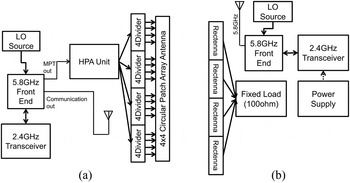
Figure 6 shows the block diagram of the time-division operation evaluation. The 2.4 GHz band transceiver in the base station was utilized for generating signals both wireless communication and MPT. A mixer, an amplifier, and a SPDT switch are integrated into the 5.8 GHz front end unit. The SPDT switch is controlled by a controller in the 2.4 GHz band transceiver. The intermittent CW signal for the MPT is generated in the transceiver. The rectennas in the sensor node are directly connected to the constant load of 100 Ω. An external power supply is used for the stable operation of the sensor node during the experiment. The power supply is connected to the 2.4 GHz band transceiver, the 5.8 GHz front end unit, and the LO source.
The block diagram of the time-division operation evaluation of the wireless communication in the 5.8 GHz band and the MPT at 5.8 GHz: (a) in the base station and (b) in the sensor node.

3) The frequency-division operation
The frequency-division operation evaluated with the 2.4 GHz and the 5.8 GHz bands are used for the sensor data communication and the MPT, respectively. The sensor node transmits the data intermittently according to time sequence shown in Fig. 3. On the other hand, the MPT system operates continuously. Figure 7 shows a block diagram of evaluation for the frequency-division coexistence. Two different experiments, such as basic characteristic evaluation and balance of the electric energy/power, are conducted. The signal generator is used for the frequency-division operation measurement to generate the continuous CW signal for the MPT.
The block diagram of the frequency-division operation evaluation of the wireless communication in the 2.4 GHz band and the MPT at 5.8 GHz: (a) in the base station and (b) in the sensor node.

III. DEVELOPMENT OF MICROWAVE COMPONENTS
A) The 5.8 GHz HPA unit using the GaN high-electron mobility transistor (HEMT)
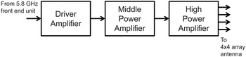
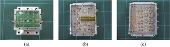
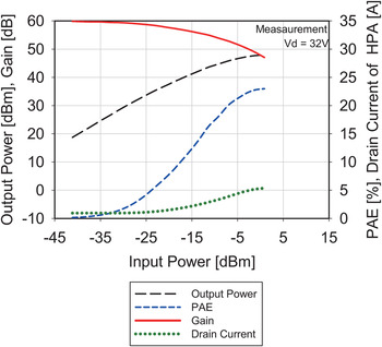
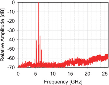
Based on Table 4, the HPA unit was developed. Required output RF power was 47.0 dBm. A block diagram of the HPA unit is shown in Fig. 8. The HPA unit consists of the driver amplifier, the middle-power amplifier, and the high-power amplifier. A parallel amplification scheme with four GaN HEMTs was used to obtain high power and to simply connect to the array antenna. Figure 9 shows the photographs of fabricated amplifiers. To evaluate the total output power and power-added efficiency (PAE), the output power characteristics from each output of the HPA unit were measured. Reference plane of the measurement is input terminal of the driver amplifier and output terminal of the high-power amplifier. The measured input–output characteristics are shown in Fig. 10. Saturated power in the HPA of 48.0 dBm was obtained when the PAE was 23.0%. The measured data satisfied the requirements shown in Table 4. The drain currents of each power amplifier were also measured and plotted in Fig. 10 for the estimation of the HPA output power in the system experiment. Figure 11 shows a measurement results of optput power spectrum from the HPA unit. The measurement result is normalized by 5.8 GHz power level. Interference to the communication from the MPT is negligible because spurious power or noise is quite low about 2.4 GHz. The 5.8 GHz MPT has no influence on the 2.4 GHz transceiver.
The block diagram of the HPA unit.

The fabricated HPA unit: (a) the driver amplifier, (b) the middle-power amplifier, and (c) the high-power amplifier.

Measurement results of the input–output characteristics of the HPA unit.

Measurement results of the optput power spectrum from the HPA unit.

B) The 5.8 GHz rectenna and the array antenna
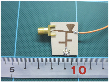
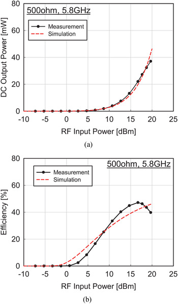
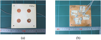
Figure 12 shows a fabricated rectifier operating at 5.8 GHz. The GaAs HEMT was utilized for rectification as a Schottky diode by grounding with source and drain. The measurement results are shown in Fig. 13. The optimum load resistance of 500 Ω was obtained in the measurement. The measured DC output power was 27.3 mW, while the efficiency was 46.3% when the input RF power was 17.7 dBm. Degradation with 2.7 mW from the designed value shown in Table 4 was measured. Figure 14 shows the fabricated 2 × 2 rectenna array using the rectifier described above. Four rectifier circuits were directly soldered in the back side of circular patch elements. DC output cables were also soldered to output terminals of each rectifier.
The photograph of the fabricated 5.8 GHz rectifier.

Measurement results of the rectifier: (a) the DC output power and (b) the RF–DC conversion efficiency.

The photograph of the fabricated 2 × 2 rectenna array: (a) the front side and (b) the back side.

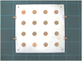
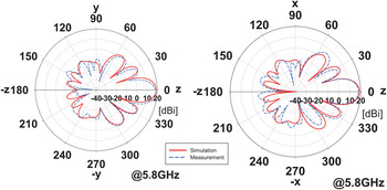
Figure 15 shows the fabricated 4 × 4 circular patch array antenna for the MPT. The dividers with 1:4 were soldered directly to back side of the antenna substrate. Figure 16 shows radiation patterns at 5.8 GHz. Calculated and measured gains were 18.9 and 18.1 dBi, respectively.
The fabricated 5.8 GHz 4 × 4 circular patch array antenna.

Measurement results of radiation patterns of the 4 × 4 array antenna.

C) The base station and the sensor node
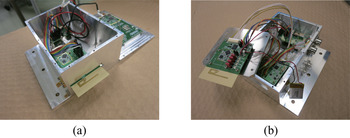
Like the base station and the sensor node, we developed the 2.4 GHz band transceiver. Figure 17 shows the fabricated base station and the sensor node. The 5.8 GHz front-end unit was used to up-convert the 2.4 GHz signal to 5.8 GHz. The 4-ch pressure sensor node is shown in Fig. 17(b). The 2.4 GHz band wireless communication substrate, the sensor control substrate, the battery, the battery charge control unit, and the IO substrate were packaged into an aluminum case. The 2 × 2 rectenna was placed on the case of the sensor node. The planar-inverted F antenna (PIFA) is integrated into the substrate of the circuit and extended out from the case.
Photographs of the fabricated base station and the sensor node: (a) the base station and (b) the sensor node.

IV. SYSTEM CONSIDERATIONS FOR COMPATIBILITY AND SUSTAINABILITY
Coexistence by the time-division operation as well as the frequency-division operation is considered in this section. The 2.4 GHz band wireless communication system and the 5.8 GHz MPT system were used for the frequency-division operation. On the other hand, as the time-division operation, the 5.8 GHz band wireless communication system and the 5.8 GHz MPT system were used.
A) Evaluation of the 5.8 GHz MPT system
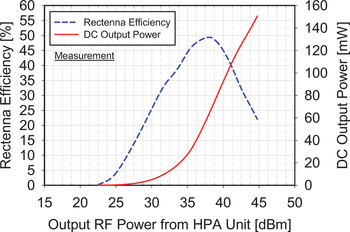
Characteristics of the MPT system were measured using the experimental setup shown in Fig. 5. Distance between antennas was 80 cm. Figure 18 shows the measurement results of the DC output power and the RF–DC conversion efficiency from the four rectennas. The DC load resistance of 100 Ω was used in the experiment. The maximum output DC power and the output RF power from the base station were obtained with 152 mW and 31.6 W (45 dBm), respectively. Since this power fulfilled the requirement of the system, we have confirmed that the fabricated four rectifiers successfully operated at 5.8 GHz band.
Measurement results of the DC output power and the RF–DC conversion efficiency of the four rectennas.

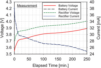
To verify the stable operation and battery charge function, the continuous operation experiment for 240 min was carried out. The lithium-ion battery was charged up by the MPT. The battery capacity is 150 mAh. Figure 19 shows measurement results of the experiment. The time-sharing signal from the base station was used as the MPT source signal in the experiment. The duty cycle of the MPT time was 80%. The battery was fully charged up since the battery voltage is raised from 3.55 to 3.89 V. The battery charge unit worked normally under coexisting with the MPT system and stable operation of the system was verified during the experiment over 240 min.
Measurement results of the battery charging by the MPT system.

B) Total evaluation of the time-division operation
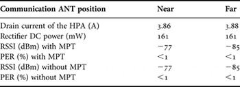
To demonstrate coexistence by the time-division operation, the communication quality and the MPT characteristics were measured. To investigate interference, the communication antenna adjacent to the MPT antenna or at 30 cm away from the MPT antenna was settled and measured their characteristics. The base station antenna for the 5.8 GHz band communication was the single-element circular patch and those for the MPT were the 4 × 4 circular patch array, respectively. The single-element patch antenna was also used for the communication antenna in the sensor node. Measured results are shown in Table 5. The output power of the HPA and that of wireless communication were 38.0 W (45.8 dBm) and 2.7 mW (4.3 dBm), respectively. From the measurement results, it is found that the MPT characteristics were not affected while the RSSI changed. As a result, it was confirmed that the coexistence operation with the MPT and the communication was achieved for both antenna locations. The communication antenna can be placed beside the MPT antenna or rectenna.
Dependence on the communication antenna location for the time-division operation.

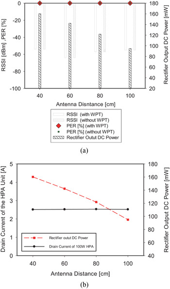
System performance relating to location of the base station and the sensor node was measured. The parameter investigated in the measurement was the antenna distance only. Figure 20 shows the experimental data as the function of distance between transmitting antenna and that of rectenna for the MPT. The output power operating in the wireless communication with the MPT was not changed during the measurement. The communication antenna was placed adjacent to the MPT antenna or the rectenna. The optimum load resistance of 100 Ω was chosen as the load resistor of the rectennas. The system performance was measured under the condition of antenna distance from 40 to 100 cm. The RSSI and the rectifier output power increased as the antenna distance decreased. In addition, the PER showed <1% for all antenna distance. The RSSI and the PER were not affected, while the MPT was switched on or off by the time-division operation. Therefore, it was confirmed that the proposed system is effective for the coexistence operation.
Dependence on antenna distance for the time-division operation: (a) the RSSI, the PER, and the rectifier output power and (b) the drain current of the HPA and rectifier output power.

C) Total evaluation of the frequency-division operation
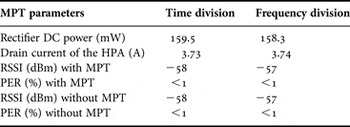
Interference between the wireless communication and the MPT should be concerned to realize the frequency-division operation, since the high power in the MPT system was transmitted during the communication timeslot. From this point of view, two MPT methods of the time-division (single-tone by switching alternative functions) operation and frequency-division (multi-tone by continuous wave) operation were examined. In case of the frequency-division operation, the 2.4 GHz band was used in the communication system and the 5.8 GHz was done in the MPT system. The output power of the MPT was estimated with 45.8 dBm from drain current of the HPA. Comparison of measurement data are shown in Table 6. As for the frequency-division operation, the wireless communication system was not affected by the continuous MPT system. Using the frequency-division operation, the rectifier output power of 161 mW, the RSSI of −58 dBm and the PER with <1% were measured. From these results, it is believed that effectiveness of the frequency-division operation was validated.
Dependence on the MPT parameters.

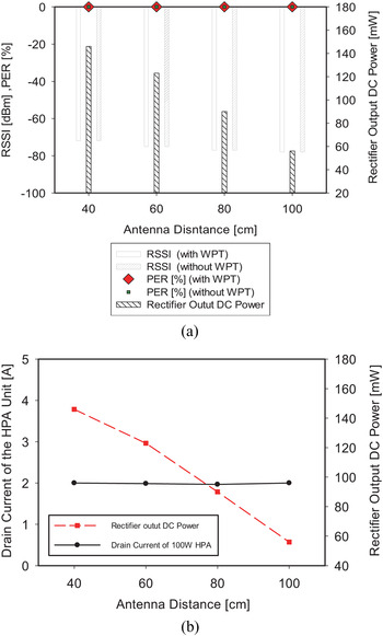
To investigate the dependence of the sensor location, the RF power level, the RSSI, the PER, and the rectifier output DC power were measured at each different antenna distance between the base station MPT array antenna and the sensor node rectenna. The experimental results of dependence of the antenna distance were shown in Fig. 21. The output RF power of the MPT system was not changed during the measurement. The RSSI showed no dependence on the antenna distance. This is because the main beam direction of the PIFAs were not oriented each other. Depending on direction of communication partner, the antenna gain changes. The PER was <1% while the experiment, hence, high communication quality is kept enough for the sensor data transmission. On the other hand, from the view-point of the MPT system evaluation, the rectifier output power increased when the antenna distance became short. In addition, strong dependence on the distance was confirmed. The maximum distance between the MPT antennas was 80 cm since the minimum requirement of the DC power with 120 mW was satisfied. For the optimum MPT performance in the real spacecraft, the propagation loss should be carefully considered when deciding the location of the sensor nodes.
Dependence on antenna distance for the frequency-division operation: (a) the RSSI, the PER, and the rectifier output power and (b) the drain current of the HPA and the rectifier output power.

D) Power balance between the MPT and the communication data transmission
The power balance between the rectifier output power by the MPT and consumption power in the sensor node was evaluated to show the system stability and reliability by experiment. The frequency-division/multi-tone operation was applied for the power balance evaluation. Therefore, if the power balance between the dissipation in the sensor and the power supply by the MPT is achieved, it is expected that the battery-less wireless sensor system is realized through simultaneous data transmission in one frequency band with power supply by the MPT in another frequency band.
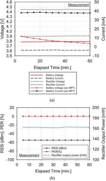
The power balance test was carried out for 120 min. Figure 22 shows measurement results within 60-min operation out of 120 min. Since the rectifier output power was 162 mW, the MPT output power was assumed to be 38.0 W (45.8 dBm). The RSSI of −55 dBm and the PER of <1% were kept under the stable operation for at least 60 min. In addition, the battery voltage was reduced to operate the sensor without the MPT, whereas the battery voltage slightly increased from 3.78 to 3.80 V due to the power supply by the MPT. This result means the MPT powering compensated power consumption in the sensor node. From more detailed investigation, it was found the surplus power confirmed with minus value in the battery current was used for battery charging.
Long-time operation measurement results using the frequency-division operation (within 60 min): (a) the voltage and current of the battery and rectifier and (b) the RSSI, the PER, and the rectifier output power.

To evaluate the electric power balance in detail, the output power of the rectifier and that of the regulator were calculated. The electric energy per one time sequence in four timeslots (4000 ms) was calculated by the following equations:
 $$EE_{Rect.} = P_{Rect.} \cdot 4000,$$
 $$EE_{Reg.} = EE_{RX} + EE_{TX} + EE_{idle},$$
 $$EE_{RX} = P_{RX} \cdot T_B,$$
 $$EE_{TX} = P_{TX} \cdot (T_d + T_F ),$$
 $$EE_{idle} = P_{idle} \cdot (4000 - T_B - T_d - T_F ),$$
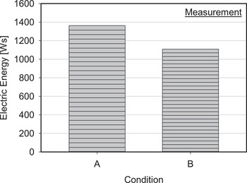
where EE Rect ., EE Reg ., P RX , PTX , and P idle are the electric energy of the rectifier output power, that of the regulator output power, the consumption power while receiving, that while transmitting, and that while idling, respectively. The dimension of T B , Td , and T F is in millisecond. Figure 23 shows measurement results of the power balance in the sensor node under 120-min operation. Conditions A and B indicate the rectifier output power (income) and the regulator output power (expenditure), respectively. The electric energy per 5 min is stacked in the figure. The total electric energy of the income and the expenditure were 1362.7 and 1109.0 Ws, respectively. The favorable balance was confirmed since the income energy exceeded the expenditure with 253.7 Ws. Therefore, the sustainable and stable operations as well as the coexistence were confirmed from the experiment.
Power balance in the sensor node. Conditions A and B mean the rectifier output and the regulator output, respectively.

From observing the measurement results, it is obvious that the combination of the time- and the frequency-division operations is effective for the coexistence. Furthermore, since fundamental data through the experiment results were obtained in the anechoic chamber, evaluation of validity using the RVT with the aero-shell should be carried out for the practical use.
V. CONCLUSION
In this paper, the aerospace wireless sensor network system for coexistence of the high-power MPT and the wireless communication have been described. For the MPT and wireless communication coexistence, the time- and the frequency-division operations were adopted. Regarding the frequency-division operation, the rectifier output DC power of 161 mW, the RSSI of −85 dBm, and the PER of <1% were obtained. At the measurement, the compact and high-power GaN HPA for the MPT with saturated power of 48.0 dBm was used. In addition, the long-time operation experiment was carried out using the frequency-division operation. The stable operation was achieved and the power balance of 253.7 Ws was measured while in the 120-min continuous operation. It was confirmed the feasibility of the proposed coexistence operations to be used for completely wireless sensor network system in the future spacecraft.
ACKNOWLEDGEMENTS
The authors would like to thank C. Maekawa, I. Urushibara, and H. Sato of AR'S CO., LTD. for their help in fabricating substrates and discussion of the control method. Also, the authors would like to express deep gratitude to H. Yamazawa of CHINO CORP for his cooperation of providing sensors.
 Satoshi Yoshida was born in Saga, Japan, in 1984. He received his B.S., M.S., and Ph.D. degrees in Electrical and Communication Engineering from Tohoku University, Sendai, Japan in 2007, 2009, and 2012, respectively. He is currently an aerospace project research associate with the ISAS, JAXA. His main research interests include microwave power transfer system for space application, rectenna and high-power amplifier, active integrated antennas, and millimeter-wave antenna systems for space communication.
 Naoki Hasegawa was born in Aichi, Japan. He received his B.E. degree in Electrical and Electronic Engineering from Ritsumeikan University, Siga, Japan, and his M.E. degree in Electrical Engineering from Kyoto University, Kyoto, Japan, in 2011 and 2013, respectively. He is a member of the Institute of Electronics, Information, and Communication Engineers (IEICE), Japan.
 Shigeo Kawasaki received the B.S. and M.S. degrees in Electrical Engineering from Waseda University in 1979 and 1981, respectively and Ph.D. degree in Electrical Engineering from the University of California, Los Angeles (UCLA) in 1993. In 1990, he was the Research Assistant at The University of Texas, Austin. From 1991 to 1993, he was the Graduate Student Researcher at UCLA. Since April 1994, he has been with Tokai University, Japan as the Professor in the Department of Electrical and Electronics Engineering. In 1997, he was the Invited Visiting Scholar at UCLA and, in 1999, the Invited Visiting Professor at California Institute of Technology, respectively. In 2004, he temporally joined as the Adjunct Professor in University of Hawaii at Manoa, USA and joined as the Professor in the Research Institute for Sustainable Humanosphere, Kyoto University, Japan. From October of 2008, he has joined as the Professor in ISAS/JAXA, Sagamihara, Japan. His research activities include the microwave and millimeter-wave active integrated antenna technique, its optical control, the nonlinear active device modeling, high-power integrated circuits, an active phased array antenna, and an electromagnetic analysis for a microwave simulator.