

Introduction
The stapes and its footplate are crucial to the transmission of sound from the aerated middle-ear environment to the liquid inner-ear environment. The stapes is the smallest bone in the human body. Any pathology of the stapes (malformation, dystrophy, infection or trauma) can induce conductive hearing loss.
Standard temporal bone computed tomography (CT) consists of reconstructions in the semicircular canal plane and frontal plane, which allows only piecemeal study of the stapedial superstructure and footplate.Reference Lemmerling, Stambuk, Mancuso, Antonelli and Kubilis1 The stapes axial plane seems more appropriate for analysis of this ossicle,Reference Henrot, Iochum, Batch, Coffinet, Blum and Roland2 being strictly parallel to the stapedial superstructure. The incudostapedial joint should be painstakingly analysed in post-traumatic hearing loss. Footplate thickness and density should be assessed in cases of chronic otitis media, otospongiosis or congenital hearing loss.
The present study sought to determine stapes axial plane position with respect to the lateral semicircular canal, and the principle normal measurements as taken on stapes axial plane CT.
Materials and methods
Data acquisition
A total of 208 normal temporal bone CT scans from 140 patients (with a mean age of 42 years) were analysed retrospectively. All scans were performed using a Siemens Somatom Volume Zoom four-slice machine (Siemens Healthcare, Forchheim, Germany), with acquisition in a suborbitomeatal plane at 120 kV, 250–300 mA. The mean dose–length product was 350 mGy · cm.
Data processing
A Leonardo Workstation (Siemens Healthcare) was used for image reformatting. The reformatted images consisted of overlapping sections of 0.6 mm every 0.4 mm in the stapes axial plane. Obtaining the stapes axial plane required three-fold positioning. First, the axial plane was positioned in the plane of the semicircular canal. Second, the oblique coronal plane was obtained after positioning the slices perpendicular to the footplate in the lateral semicircular canal plane, so that the V-shape formed by the incudostapedial joint and the stapes was visible. Third, the stapes axial plane was obtained in the oblique coronal plane, and the slices were positioned parallel to the stapes crura. This plane contained the superstructure and the long axis of the footplate.
Inclusion and exclusion criteria
Clinical and imaging criteria were used to select the analysed ears. The inclusion criterion was normal hearing in the analysed ear. Exclusion criteria were: stapedial malformation, otic capsule hypodensity, or tissular or liquid filling of the tympanic cavity.
Data analysis
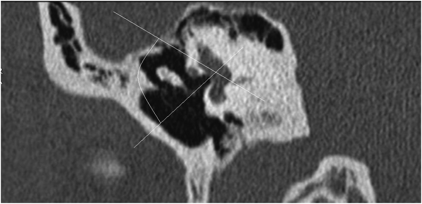
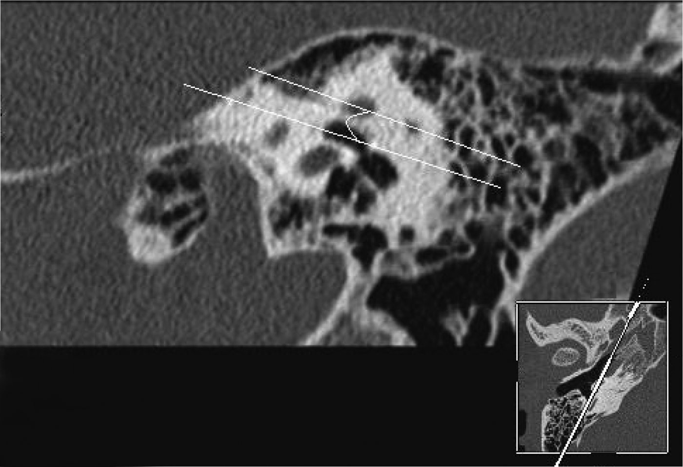
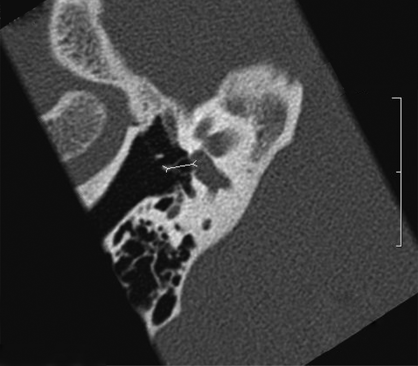
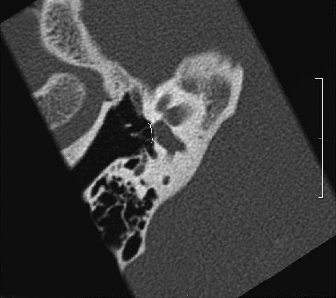
The following measurements were calculated for each analysed ear, based on consensus between two senior neuroradiologists (PM and JR): (1) the angle subtended by the lateral semicircular canal and stapes axial plane, in the oblique frontal plane containing the V-shape (Figure 1); (2) the angle subtended by the lateral semicircular canal and the main axis of the footplate, in an oblique sagittal plane (Figure 2); (3) the distance between the head and footplate (Figure 3), and the superstructure width (Figure 4), on stapes axial plane; and (4) central footplate thickness on lateral semicircular canal and stapes axial plane, and incudostapedial joint width on stapes axial plane, both measured directly by calipers and by calculating density peak width at the midpoint (Figures 5–7).
Oblique coronal plane computed tomography image showing the angle between the lateral semicircular canal and stapes superstructure.

Oblique sagittal plane computed tomography image showing the angle between the lateral semicircular canal and the main axis of the footplate.
Stapes axial plane computed tomography image showing the head–footplate distance.
Stapes axial plane computed tomography image showing the stapes superstructure width.
(a) Stapes axial plane computed tomography image showing the footplate density position axis, and (b) graph showing footplate density peak midpoint width measurements on density position axis on stapes axial plane (position is measured on the axis referred to in figure part (a)).
(a) Lateral semicircular canal plane computed tomography image showing the footplate density position axis, and (b) graph showing footplate density peak midpoint width measurements on density position axis on lateral semicircular canal plane (position is measured on the axis referred to in figure part (a)).
(a) Stapes axial plane computed tomography image showing the incudostapedial joint density position axis, and (b) graph showing incudostapedial joint negative density peak midpoint width measurements (position is measured on the axis referred to in figure part (a)).
Results
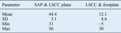
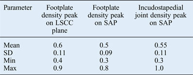
The results for angles, distances and density peak widths are presented in Tables I–III. Distances measured by calipers, and density peak widths at the midpoint, are shown in millimetres. Measured angles are presented in degrees. For each value, the means, standard deviations and ranges are provided.
Stapes axial plane and lateral semicircular canal plane, and lateral semicircular canal and footplate angles
Data represent angles (°). SAP = stapes axial plane; LSCC = lateral semicircular canal; SD = standard deviation
Stapes measurements on stapes axial plane and lateral semicircular canal plane
Data represent distances (mm). LSCC = lateral semicircular canal; SAP = stapes axial plane; SD = standard deviation
Density peak midpoint widths
Data represent widths (mm). LSCC = lateral semicircular canal; SAP = stapes axial plane; SD = standard deviation
Discussion
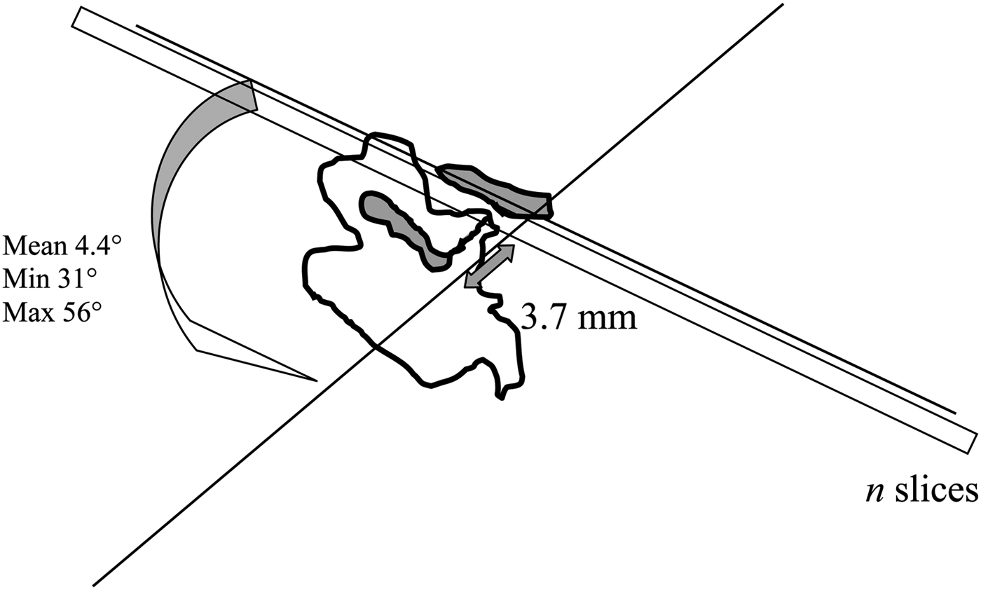
The mean angle subtended by the lateral semicircular canal and stapes axial plane was 44.4°. It is this angle that indicates the stapes axial plane. For a mean head–footplate distance of 3.7 mm, 4 to 6 consecutive 0.6 mm slices are needed on lateral semicircular canal plane (according to the formula n = 3.7× sin (31° and 56°) / 0.6 (Figure 8), rounded up to the nearest whole number: n = 4 and 6), whereas a single slice, if correctly positioned, is enough on stapes axial plane.
Theoretical number of slices needed to cover the stapes on lateral semicircular canal plane: n = 3.7 × sin (31 to 56) / slice thickness.
The angle subtended by the lateral semicircular canal plane and the main axis of the footplate was 12.1°. Thus, the so-called parallelism between the lateral semicircular canal, the tympanic part of the facial nerve and the footplate is not exact.Reference Veillon, Riehm, Emachescu, Haba, Roedlich and Greget3 The mean maximum stapes superstructure width was 2.7 mm, so that a perfectly centred 0.6 mm slice could only contain the entire superstructure if the angle was less than 12.8°, according to the formula α = sin−1(0.6 / 2.7) (Figure 9). For angles between −5° and 12.8°, the problem is circumvented by the partial volume induced by slice thickness. For angles greater than 12.8° (46 per cent in the present series), the stapes axial plane as defined above needed to be tilted forward so as to enable visualisation of the anterior and posterior stapes branches in a single slice.
Maximal anterior stapes tilt angle for the slice plane to contain the entire superstructure: α = sin−1 × slice thickness ÷ 2.7) = 12.8°.
The mean head–footplate distance was 3.7 mm, for a width of 2.7 mm. These values are in agreement with ex vivo measurements on ‘dry’ stapes.Reference Dass, Grewal and Thapar4–Reference Legent, Perlemuter and Vandenbrouck6 These measurements should be taken in cases of suspected fracture or branch malformation.
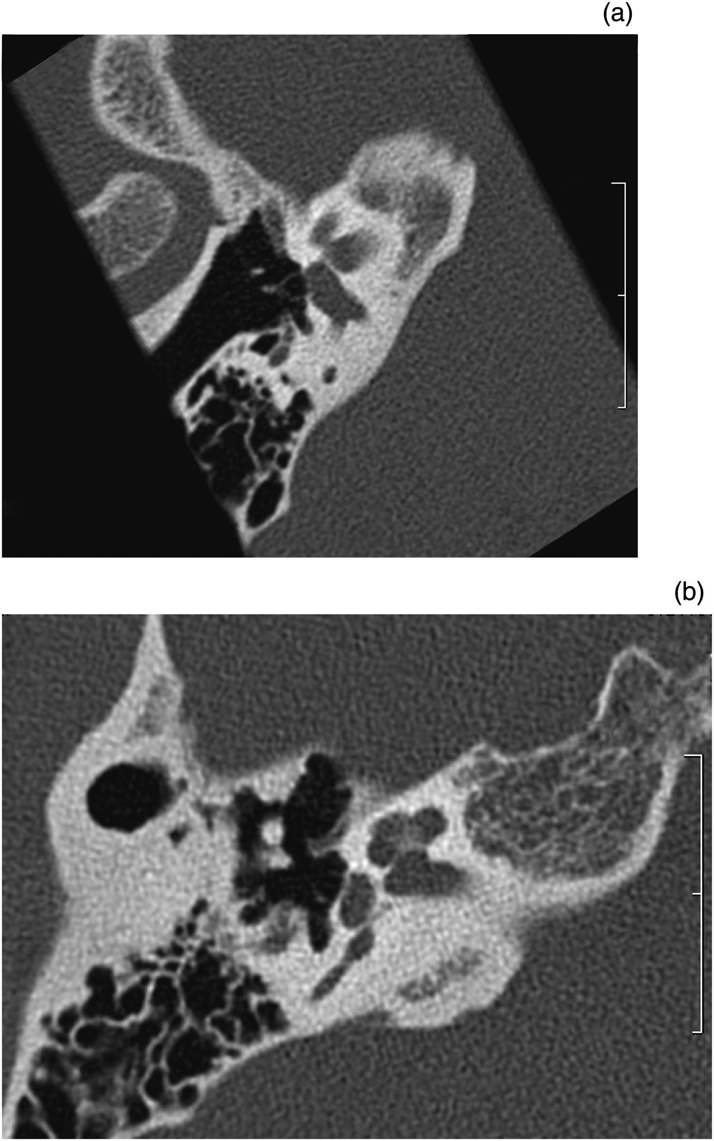
Footplate thickness has been assessed by various methods. We hypothesised that thickness on stapes axial plane would be less than the lateral semicircular canal plane values reported in the literature. In the present series, the mean thickness was 0.27 mm on stapes axial plane, versus 0.42 mm on lateral semicircular canal plane (Figure 10); this difference was significant (p < 0.01, matched z-test). Likewise, the stapes axial plane value was lower than that reported in the literature, in which thicknesses vary from 0.48 to 0.5 mm.Reference Veillon, Riehm, Emachescu, Haba, Roedlich and Greget3, Reference Schuknecht and Kirchner7, Reference Veillon, Stierle, Dussaix, Ramos-Taboada and Riehm8 This is explained by the downward and outward obliqueness of the stapes axial plane and of the footplate, which induces a partial volume effect. Thickness measured ex vivo on dry stapes was found to range from 0.15 to 0.25 mm.Reference Veillon, Riehm, Emachescu, Haba, Roedlich and Greget3 The slightly higher value (0.27 mm) reported in the present study can be explained by the fuzziness generated by the scanner detector. A footplate thickness equal to or greater than 0.5 mm on stapes axial plane should be considered abnormal.
• The stapes is difficult to analyse on computed tomography (CT) because of its small size and oblique orientation
• The incudostapedial joint should be painstakingly analysed in post-traumatic hearing loss
• Footplate thickness should be assessed in cases of chronic otitis media, otospongiosis or congenital hearing loss
• The stapes axial plane parallel to the superstructure seems optimal for such analyses
• This retrospective study comprised 208 CT scans of normal ears
• Central footplate thickness was less than 0.5 mm on stapes axial plane and incudostapedial joint width was less than 0.7 mm
Computed tomography images showing the stapes footplate on (a) stapes axial plane and (b) lateral semicircular canal plane (same patient, same examination); the difference in thickness is obvious.
We compared footplate density position curves on stapes axial plane and lateral semicircular canal plane. The density peak on stapes axial plane could not always (in 35 per cent of cases) be distinguished from the endolymphatic fluid; this was due to the thinness of the footplate and lack of precision in density measurement as a result of noise. When peaks were identifiable, the mean midpoint width was 0.5 mm (±0.09). On lateral semicircular canal plane, density peaks were always identifiable, with a mean midpoint width of 0.6 mm (±0.11). This difference in peak width was significant (p < 0.05, matched z-test). This density curve analysis confirmed that fuzziness was greater on lateral semicircular canal plane than on stapes axial plane.
The mean incudostapedial joint width on stapes axial plane was 0.32 mm (range, 0.2–0.5 mm). The mean negative density peak midpoint width was 0.55 mm (range, 0.3–1.0 mm). Joint width should be assessed in cases of trauma. Incudostapedial dislocation is the most frequent traumatic lesion of the ossicular chain.Reference Meriot, Veillon, Garcia, Nonent, Jezequel and Bourjat9 According to Swartz et al., the joint interline should not exceed 1 mm.Reference Swartz, Zwillenberg and Berger10 We consider incudostapedial joint width equal to or greater than 0.7 mm as abnormal.
The limitations of the present study lie in the single-centre design and debatable inclusion criterion. Such measurements, however, could not be made in healthy volunteers using irradiating technology. Footplate thickness was assessed only at the centre, so as to facilitate comparison between the stapes axial plane and lateral semicircular canal plane.
Conclusion
Compared with the lateral semicircular canal, the stapes axial plane is tilted downward, outward (44°) and slightly forward (12°). This enables the stapes superstructure to be analysed on a single slice. In this retrospective series of 208 cases, central footplate thickness was systematically less than 0.5 mm on stapes axial plane and incudostapedial joint width was systematically less than 0.7 mm.