1. INTRODUCTION
In the study of GNSS integrity, SISE generally refers to satellite ephemeris error including satellite orbital error and clock error. This is one of main error sources in all kinds of navigation and positioning applications. Moreover, SISE is an important factor, which affects the service integrity of navigation systems, since it synthetically reflects the performance of the ground control and space constellation segments. The real-time monitoring SISE has been one of the current effective solutions to improve GNSS system-level integrity (Quiles et al., Reference Quiles, Schlarmann, Ballereau, Hollreiser, Durand, Robert and Schmid2009; Oehler et al., Reference Oehler, Krueger, Beck, Michael, Hans, Hahn and Daniel2009; Curiel et al., Reference Curiel, Martín, Juez, Ramírez, Igual, Amarillo, Ballereau and Schlarmann2009). The most typical real-time monitoring is the Galileo integrity concept. Although the Galileo plan develops slowly due to many factors, it has produced many innovations in the design, especially in the system-level integrity. Thus it will function to promote the advancement of system-level integrity.
From the navigation users’ perspective, especially in safety critical applications, if the ephemeris error projections onto the line-of-sight direction of every visible satellite in time can be obtained, the integrity risk which the user may suffer can be assessed on time. This enables the user to make decisions as to whether satellite navigation should be used as the main navigation means or not to avoid dangerous risks caused by the SIS failures. Since the projection of ephemeris error on line-of-sight direction changes depending on the users’ location and time, every satellite can only provide users the maximum ephemeris error projection in its service volume to satisfy all the potential users. The WUL is a key parameter to estimate the maximum ephemeris error projection. An improved WUL algorithm is presented in this paper, following its performance validation and analysis with GPS raw data.
Many studies focus on the WUL algorithms, which can be divided into two sorts: grid search-based algorithms and geometrical model algorithms. The former is straightforward and reliable, but time consuming and its precision is highly related to the grid spacing. This paper focuses on the latter. Feng et al. (Reference Feng and Washington2005) has given an algorithm of the latter type, which calculates the WUL based on a spherical model firstly and then computes the WUL on an ellipsoidal model by iteration. Although this method is deduced rigorously, it is complex. Moreover, its iterative part is also related to the search space. (Guo et al. (Reference Guo, Zhao, Dang and Lu2007) has put forward another geometrical model algorithm which is less complicated than the algorithm developed by Feng et al. However, part of the geometrical deduction in Guo's algorithm is not rigorous and iteration and search processes are also used to find the WUL based on an ellipsoidal model (Guo et al., Reference Guo, Zhao, Dang and Lu2007). This paper tries to propose a WUL algorithm which not only meets the accuracy requirement but also is reliable and not time consuming.
2. BASIC PRINCIPLE OF GALILEO INTEGRITY CONCEPT
The current basic principle of the Galileo integrity concept is mainly based on the theory proposed by V. Oehler et al. (Reference Oehler, Krueger, Beck, Michael, Hans, Hahn and Daniel2009). Until now there have not been any official releases or issues to expatiate the final Galileo integrity concept. The aim of the Galileo integrity concept is, by using two different integrity information chains, to help users obtain the real-time SIS quality and evaluate the integrity risk undergone when using the SIS for navigation and positioning. The first information chain is SISA, which is produced from the department in charge of orbit determination and time synchronisation. SISA can be used to evaluate the influence on users exerted by the ephemeris error produced by the control segment. The second chain is SISMA, which is produced by the ground monitoring net units distributed around the world and can be used to monitor the accuracy of every satellite SIS and to transmit the potential integrity risk flag to every satellite through the control segment in time. WUL is needed to get both of the above information chains (Oehler et al., Reference Oehler, Francesco, Boyero, Roland, Hans, Hahn, Amarillo, Crisci, Schlarmann and Flamand2004; Oehler et al., Reference Oehler, Hans, Krueger, Rang, Francesco, Boyero, Hahn and Daniel2006). Actually, the WUL information needed by the Galileo integrity concept is just a direction vector, that is to say, it is the vector from the satellite to the worst users’ locations in the service volume. Here, let the vector be u W. If WUL is known, u W can be calculated according to the satellite position and thus the SISA and SISMA can be computed easily.
3. WUL COMPUTATION PROCESS
The WUL computation can be categorised into two cases based on the relationship between the SISE vector u E1 (or u E2) and the satellite position vector S v. One case is that the intersection between the extending line of u E and the Earth is in the satellite's service volume. On the Earth's surface, if the shape abnormality resulting from the upper objects is not considered, the service volume of one satellite is just an ellipse with its foot point as the ellipse's centre. If the Earth is seen as a sphere the ellipse will become a circle known as a ‘dangerous circle’. The circle with its centre at point P in Figure 1 is a ‘dangerous circle’. In this case, the extending line of u E1 intersects the Earth's surface on the ‘dangerous circle’. Another case is that the extending line of u E2 intersects the Earth's surface outside the ‘dangerous circle’, or beyond the Earth's surface. In this case, the WUL is at the intersection between the ‘dangerous circle’ and the plane determined by u E and the Earth's centre. There are two such intersections possible. They can be chosen according to the relationship between the SISE vector and the S v, or according to the SISE projections calculated with these intersections as the input. The WULs in these two cases are denoted as W1 and W2 respectively, just as Figure 1.
Distribution sketch of two WULs’ cases.

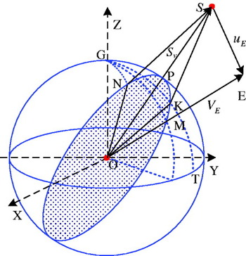
According to the above analysis, taking the Earth as a spherical model, there are two cases to calculate the vector u W with part of the computing process being the same. Without considering the case that the SISE vector u E1 is the same as the S v, the geometrical relationships of the known information can be seen in the plane determined by S v and u E1 (or u E2) just as in Figure 2. The direction vector from the Earth's centre to point E is denoted by V E Therefore,

where, V E intersects the Earth at M, so the location of M can be obtained from V E. The coordinates of E are (x E, yE, zE), so the spherical surface latitude and longitude of M can be calculated from the following formulas:
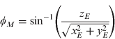
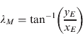
Similarly the spherical surface latitude and longitude of the satellite foot point P can be calculated according the satellite's coordinates. Next, discussion will be carried out in the plane SOE.
Plane sketch of WUL on dangerous circle.

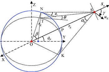
As is shown in Figure 2, for the spherical model, points N and K are intersections of the ‘dangerous circle’, the plane is formed by S v and u E and θ 0 is the mask angle, which is fixed and equal to 5 degrees without special explanation. The Earth radius is r E and the satellite's geocentral range is r S·a 0 is the nadir angle for the mask angle θ 0 and β is the corresponding central angle for the same mask angle. Therefore,
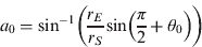
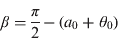
The angle between the vectors u E and S v can be calculated from:
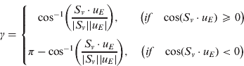
where, [·] is the dot product and 0⩽γ⩽π.
Now, it is easy to judge whether the WUL is on the ‘dangerous circle’ with the known γ and a 0. If γ<a 0, WUL is on the ‘dangerous circle’ and u W is equal to the unit vector of u E; otherwise, the WUL could be at the point N or K as discussed below.
Firstly, in Figure 3, the points M (ϕ M, λM) and P (ϕ p, λp) are known and there are such relations as GM=r E·(π/2−|ϕ M|), GP=r E·(π/2−|ϕ p|) and ∠PGM=|λ p−λ M|, where both GM and GP are arcs. Then in the spherical triangle GPM, the arc PM can be computed by:

And an angle can be determined with the law of sine as follows:

Similarly, considering the arc PK=r E · β, in the spherical triangle GPK, there exist the following relations:

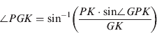
Thus, the possible latitudes and longitudes of point K are ϕ K=±(π/2−GK/r E) and λ K=λ p±∠PGK. Similarly, in the spherical triangle GPN, the possible latitudes and longitudes of point N are; ϕ N=±(π/2−GN/r E), λ N=λ p±∠PGN. The plus/minus sign in the above four expressions includes all possible cases. The way to accept or reject it is to choose the case that results in the largest SISE projection error. This method not only omits the judgments among several geometrical cases, but also omits the case that the WUL appears on the ‘dangerous circle’ at the other side of point P when γ is larger than 90 degrees just as the point N in Figure 3. When γ is equal to 90 degrees, the intersections N and K are all theoretically acceptable, which results in multi-solutions. Actually, this case is of small probability.
Spherical sketch of WUL at the dangerous circle.

The WUL computation based on the spherical model is now finished; next, it is necessary to transform the WUL from the spherical model to the ellipsoidal model. As is known to all, the transformation work only relates to latitudes.
Still taking Figure 2 into account, the point on the ellipsoidal model corresponding to the point N on the spherical model is T. Although both T and N have the same latitudes, the mask angle θ of T is less than θ 0, so T is not on the ‘dangerous circle’. Here, it is necessary to move T in the decreasing direction until θ approaches θ 0 with the desired accuracy. The approximate way to transform from N to T is given as follows. For the details one needs to refer to the literature (Tsui, 2005). If the latitude of T is denoted by ϕ T, then:


where, e is the flattening of the Earth. And for the WGS-84 ellipsoid, e equals 1/298·257223563. The above expression is a non-linear relation, which can be figured out by iteration without considering the higher-order small ε. Furthermore, it gives the difference between the spherical model and the ellipsoidal model as δϕ≈e · sin(2ϕ T). The largest difference will occur at the latitude of 45 degrees, which is where the Earth flattening approximately equals 11·526′. The higher-order small ε is less than 1·6″.
4. ACCURACY REQUIREMENT OF WUL
The final aim of the WUL lies in projecting SISE onto the line-of-sight direction to achieve the largest error projection, which makes a strong impact on ranging accuracy. Considering that the ranging resolution and ranging error have a great impact on the ranging accuracy, it is necessary to study the SIS ranging resolution and ranging error to analyse the accuracy requirement of the WUL. The ranging resolution is determined by the digits of the Numerically Controlled Oscillator (NCO) in the Delay Lock Loop (DLL). Taking GPS C/A for instance, the resolution of a NCO of 16 digits is 1·4916×10−11 seconds, which equals 0·0045 metres. The ranging error depends on such factors as the signal-to-noise, the type of DLL, the distance between the early and late correlators, the coherent integration time and the tracking loop band (Kaplan, Reference Kaplan1990). Also taking GPS C/A for instance, when the input power level is −133 dBm, the ranging error will reach about 0·5 metres. Based on the above analysis, the ranging uncertainty mainly depends on ranging error. Additionally, considering the model error of the ionosphere and troposphere and the multi-path effect, the final ranging uncertainty will not be better than 0·5 metres.
In addition, it is necessary to investigate the space distribution characteristics of SISE. Since the satellite clock error has the same impact on all the users in its service volume at the same time, whereas the orbital error is different depending on the location of users, for it determines the direction of the WUL. So, only the three orbital error components are considered here. The satellite to the WUL direction vector u W is expressed as;

Where, m, n and l are three direction angles of the vector u W in the ECEF frame. The corresponding orbital error vector consisting of radial, along track and cross track errors, is given as:

So, the SIS error projected onto the WUL direction is:

The above expression means that it can reach a maximum only if the signs of three error components are the same. Under the assumption that their maximums are the same, all of which are δM, in order to make SISE w the largest, consider the mathematical relation cos2m+cos2n+cos2l=1. This occurs if and only if cos m=cos n=cos l, where m=n=l=54·7356 degrees. At this point SISE w will be at a maximum.
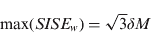
When the SISE w reaches maximum, we can analyse the impact of the WUL direction error on SISE w from two cases. The impact can be noted as;

where,  and is known as the error effect factor.
Case I: One direction has no error, another has error and the last can be determined by the relation cos2m+cos2n+cos2l=1.
Case II: Both two directions have the same error and the last can be got as above.
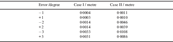
The error effect factor F in both cases is given by Table I. The first column represents the increased and the decreased error on the basis of 54·7356 degrees.
Error effect factor F for both cases.
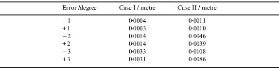
On the basis of the results from Table 1, the factor F is in direct proportion to the absolute error of the WUL direction and F reaches the maximum 0·0108 when the error is at 3 degrees. That is to say, if the maximum of every orbit error component is δM=10m, the SISE w error impact caused by 3 degrees of WUL direction error is 0·108 metres. When the error is 2 degrees, the maximum impact from both two cases is less than 5 centimetres. But for the systems like GPS, it is very conservative to make the orbital error components maximums as 3 metres. Even if the direction error reaches 3 degrees, the impact on the SISEw is only at centimetre level. That is to say, as long as the accuracy of the WUL direction does not exceed 3 degrees, it will completely satisfy the SIS like GPS C/A code signal.
In light of the above discussion, with the current metre-level orbit accuracy, the SISE projection error will remain at centimetre-level so long as the direction error of the WUL is less than 3 degrees, which can satisfy most navigation users.
The WUL algorithm can be optimised according to the above requirement analysis. The approximate model transformation in the algorithm presented above resorts to non-linear iteration. Since the accuracy improvements brought by the transformation do not exceed 0·2 degrees, the accuracy of the WUL information is good enough to transform from the spherical model to the ellipsoidal model. That is to say, it is reasonable to regard the Earth as a standard sphere to computer the WUL information. Thus, the algorithm given by this paper can completely omit the approximate transformation with non-linear iteration.
5. ALGORITHM TESTING
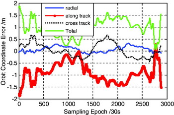
In order to verify the correctness and reliability of the optimised WUL algorithm proposed by this paper, tests have been carried out using GPS real data. GPS SISE can be calculated via interpolation and comparisons between the data from RINEX N files and the data from SP3 files provided by IGS. Since the orbital accuracy given by the precise ephemeris is just 5 cm, the precise orbit can be taken as the true orbit to compare the broadcast ephemeris with the sampling interval of 30 s. In order to assure the interpolation precision, the tests have adopted a 16-order polynomial. The broadcast ephemeris was collected on September 6th, 2010. One satellite marked as healthy was selected arbitrarily to test and analyse. Considering the difference between the clock error and orbital error, only the orbital error was tested. Figure 4 is the orbital error time series of PRN 12 in one day.
Time series of PRN12 Satellite orbit error in metres.

As is seen from Figure 4, the three orbit error components of PRN 12 change with different characteristics. In terms of accuracy, the radial component is the best, while the along track component is the worst. The along track error and cross track error are 7·3 and 2·2 times of the radial error respectively. The statistics of the orbital error accuracy are shown in Table 2.
Statistics of orbit error components (Unit: m).

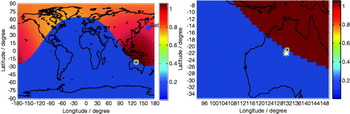
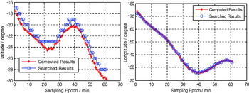
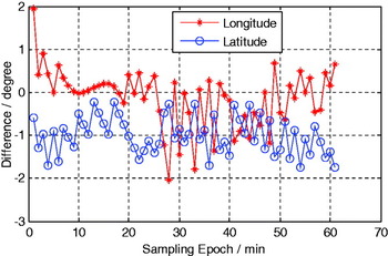
In the test, the grid-search-based algorithm is used to produce the WUL for every visible satellite at every sampling epoch. Then, the search results are compared with those of the algorithm discussed above. Both of these are shown in Figure 5, where the yellow square correspond to the grid search-based algorithm and the yellow circle to the algorithm given by this paper. The blue symbol asterisk “*” stands for the satellite foot point. The grid spacing is 1 degree×1 degree. The different colours in Figure 5 stand for the orbital error projections on the direction from the satellite to the grid point. The place where the colour value is not equal to 0 is the satellite's service volume. As is seen from Figure 5(left), the yellow square and circle are located where the colour value is the largest, which means the WUL. Figure 5(right) gives the amplificatory part case. Their locations are so close to each other in both latitude and longitude. Figure 6 gives the latitude and longitude change of the two WUL algorithms during one hour. The searched results of both latitude and longitude have leaps at some epochs, whereas the changes in the computed results are much smoother. Figure 7 gives the latitude and longitude comparison between the two WUL algorithms. If the researched results are viewed as the ones with no errors, during the hour, the maximum absolute error of latitude is 1·7412 degrees and the maximum absolute error of longitude is 2·0293 degrees. At other epochs, the results are similar. So, if assuming the maximum of the orbital component is 3 metres, the maximum impact of the WUL direction error on SISE w is only about 0·0117 metres according to Table 1, which has little influence on navigation users.
Comparison of two WUL algorithms.

Latitude (left) and Longitude (right) change of two WUL algorithms.

Differences between the two WUL algorithms.

Additionally, lots of tests have shown that the space-time distribution of the SISE's projection in the service volume changes slowly with the moving of the satellite and the changes of the three orbital error components. This means there is a strong correlation between continuous sampling epochs and that the WUL will not skip from here to there quickly. Moreover, the WUL is on the ‘dangerous circle’ in most sampling epochs.
6. CONCLUSION
A computation method for the WUL determination within the Galileo integrity concept is proposed in this paper, which has straightforward and reliable theoretical deductions when compared with the algorithms presented by other literature. The accuracy requirement is analysed on the basis of taking the orbital error scale and SIS ranging resolution and error into account. The results show that for the current metre-level orbital determination accuracy, the orbital projection error can remain at centimetre-level to meet most users’ requirements as long as the WUL direction error does not exceed 3 degrees. Based on the above conclusion, the WUL algorithm is optimised in this paper, which omits the non-linear iteration to enhance the reliability to some extent with smaller computation. This characteristic is helpful to process system integrity monitoring data in real time mode. Finally, tests are carried out with GPS data and a comparison between the algorithm proposed by this paper and the grid search-based algorithm is made. The results show that the former is correct and reliable and has a better real-time ability and smaller computation.
ACKNOWLEDGEMENT
This work was supported by the China Satellite Navigation Academy Youth Excellent Article Encouragement Sustentation Fund (Grant No. CSNC2010-QY-012), the Doctor Degree Thesis Innovation Foundation of Information Engineering University (Grant No. YJ201004), the Key Laboratory of GNSS Research (Wuhan University), Ministry of Education (Grant No. GRC-2009005).