





1. Introduction
Tokamaks are commonly described as axisymmetric magnetic fusion devices, as opposed to stellarators, which have three-dimensional (3-D) magnetic fields. However, this is a simplification. While tokamaks approximate axisymmetry, every physically constructed tokamak will have variations in magnetic field strength with toroidal angle – primarily due to the use of discrete toroidal field (TF) coils, which create TF ripple, but also due to manufacturing and assembly errors, current leads and the presence of components such as ferritic inserts or runaway electron mitigation coils. In addition, it may be desirable to induce symmetry-breaking components in the field known as resonant magnetic perturbations (RMPs) for the mitigation of dangerous instabilities such as edge-localised modes (ELMs).
Considering this, tokamaks might be considered not as axisymmetric devices, but as near-axisymmetric devices, with similarities to quasi-axisymmetric stellarators, and the class of near-quasisymmetric (QS) devices ought to be understood to include both tokamaks and a subset of stellarators. Quasisymmetry is a concept from stellarator theory which describes 3-D magnetic fields in which, in straight field line Boozer coordinates (Boozer Reference Boozer1981), the magnetic field strength
 $B$
on any flux surface is independent of a linear combination of the poloidal and toroidal angles (Helander Reference Helander2014). It is a subtype of quasiomnigeneity, which describes 3-D magnetic fields in which trapped particle drift orbits have zero bounce-averaged radial component (Hall & McNamara Reference Hall and McNamara1975), which also requires that the second adiabatic invariant
 $J_{||}$
be constant across all field lines on each flux surface (Landreman Reference Landreman2011).
Quasi-axisymmetric (QA) fields are those in which
 $B$
is independent of the toroidal Boozer angle
 $\phi$
, as in a perfectly 2-D field such as that of an ideal tokamak (Garabedian Reference Garabedian1996). No device, however, is perfectly QA: it has been proven that perfect quasisymmetry can be achieved on no more than a single flux surface within a stellarator (Garren & Boozer Reference Garren and Boozer1991; Plunk & Helander Reference Plunk and Helander2018), and while idealised (axisymmetric) tokamaks are exempt from this limitation, in the real world, as previously discussed, a tokamak built with discrete coils can never have perfectly axisymmetric field strength. Considering this, all QA devices, both tokamaks and stellarators, are only near-QA approximations of true quasisymmetry. Stellarator equilibria with deviations from quasisymmetry smaller than the magnetic field of the Earth have been found (Landreman & Paul Reference Landreman and Paul2022), and it has become possible to find nearly perfectly quasiomnigeneous stellarator equilibria, whether QS or not (Dudt et al. Reference Dudt, Goodman, Conlin, Panici and Kolemen2024; Goodman et al. Reference Goodman, Mata, Henneberg, Jorge, Landreman, Plunk, Smith, Mackenbach, Beidler and Helander2024), but like tokamaks, the necessity to generate these fields with real coils typically increases the deviations from quasisymmetry (Wechsung et al. Reference Wechsung, Landreman, Giuliani, Cerfon and Stadler2022), and that is without yet considering the potential impact of errors in constructing and assembling these complex coils.
Quasi-axisymmetric stellarators have neoclassical transport which is in many ways analogous to that of tokamaks, as in Boozer coordinates, the two device types are isomorphic (Boozer Reference Boozer1983). In particular, in both QA stellarators and tokamaks, trapped particles execute so-called banana orbits, and their plasmas tend to generate large bootstrap currents compared with non-QA stellarators. However, there are significant differences as well: stellarators (QA or otherwise) tend to see lower shear than tokamaks, particularly in the edge, which will impact transport in this region. Considering this, both tokamaks and QA stellarators should be considered as sub-classes of the larger grouping of (near-)QA fields, and methods from ‘stellarator theory’ developed for this class of field, if not dependent on qualities specific to stellarators, may produce useful results when applied to tokamaks.
For example, previous research has found that, by reducing deviations from quasi-axisymmetry, simulated losses of fast ions from stellarator equilibria can be reduced to negligible values, lower than even that of (idealised, 2-D) tokamaks (Landreman, Buller & Drevlak Reference Landreman, Buller and Drevlak2022). In addition, comparing several quantitative metrics of deviations from quasi-axisymmetry with simulated alpha power loss in power-plant-sized stellarators, correlation coefficients above 0.8 were found (LeViness et al. Reference LeViness, Schmitt, Lazerson, Bader, Faber, Hammond and Gates2023). In this work, the latter method is applied to the SPARC and ARC tokamak designs with randomised coil misalignments, and a strong correlation between QA error and predicted alpha power loss is found, replicating previous results in near-QA stellarators.
Section 2 will discuss simulations which were previously performed for ARC in Hillesheim et al. (Reference Hillesheim2026) to determine the alpha power loss assuming different types and sizes of coil misalignments. Section 3 will explore the magnitude of deviations from quasi-axisymmetry in ARC, and the relationship between a quantitative measure of this error and predicted alpha power loss. Additional coil misalignment types outside of those explored in Hillesheim et al. (Reference Hillesheim2026) will also be investigated. Section 4 will then apply the approach of analysing QA error to SPARC, considering possible coil misalignments which are within actual assembly tolerances for the device. Section 5 will compare the quasisymmetry achievable in SPARC and ARC with that found in optimised QA stellarators. Finally, § 6 will describe the conclusions of this work.
2. Fast ion loss simulations
For this work, simulations for alpha transport and loss in the SPARC and ARC tokamaks were performed. SPARC is a tokamak currently under construction by Commonwealth Fusion Systems (CFS) which aims to demonstrate net fusion energy (Q
 $\gt$
1), while ARC is the next-generation device, currently being designed, which is planned to be the first commercial fusion power plant and to deliver energy to the grid. Both are conventional aspect ratio tokamaks with coils made from high-temperature superconductor. SPARC has a major radius of 1.85 m and a minor radius of 0.57 m, with a magnetic field on axis of 12.2 T and plasma current of 8.7 MA at its design point, while ARC’s V3A design point has a major radius of 4.62 m, a minor radius of 1.18 m, a magnetic field on axis of 11.4 T and a plasma current of 12.0 MA. Further details of their designs can be found in the SPARC and ARC physics overview papers (Creely et al. Reference Creely2020a
; Hillesheim et al. Reference Hillesheim2026).
In order to predict alpha power loss from these devices, simulations were performed with ASCOT5 (Varje Reference Varje2022), a Monte Carlo orbit following code which has previously been validated against experimental data from devices like JET (Varje Reference Varje2022), ASDEX Upgrade (Hynönen et al. Reference Hynönen, Kurki-Suonio, Suttrop, Dux and Sugiyama2007) and Wendelstein 7-X (Äkäslompolo et al. Reference Äkäslompolo2019), and has been used to predict alpha losses from ITER (Snicker, Sipilä & Kurki-Suonio Reference Snicker, Sipilä and Kurki-Suonio2012) as well as many other designed fusion devices. In the simulations performed for this work, alpha particles were generated randomly spaced throughout the outer flux surfaces of the plasma, weighted by the local fusion rate and followed in 3-D magnetic fields while being subjected to collisions determined by the predicted plasma density and temperature. No radial electric field or magnetohydrodynamic effects were included. Three-dimensional magnetic fields were calculated from realistic coil geometries represented by hundreds of individual filaments, taking into account possible coil-to-coil misalignments.
These fields, which are the vacuum fields produced by the aligned or misaligned TF coil sets, were then combined with the axisymmetric poloidal field calculated by ASCOT5 from the poloidal flux of the base equilibrium, assuming that the non-axisymmetric component of the field is a small perturbation on top of the axisymmetric equilibrium. This method excludes not only the 3-D plasma response to the ripple, but also the plasma pressure contribution to the toroidal magnetic field, which, for the SPARC and ARC equilibria considered, increases the magnitude of the TF by up to 0.60 and 0.15 T at the core, respectively. The change to the field is minimal, however, in the edge region from which the particles are lost, so the zero plasma pressure (
 $\beta$
) TF should be a reasonable approximation for our simulations. Test simulations were performed with one misaligned coil set each for SPARC and ARC, using a toroidally symmetric correction to
 $B_\phi$
meant to approximate the plasma contribution, and the results agreed within statistical uncertainty (see § 2.1).
For the ARC simulations, coil sets were chosen with random misalignments in the radial and toroidal directions selected from Gaussian distributions with standard deviations
 $\sigma$
ranging from 0.5 to 8 cm, rejecting misalignments greater than
 $1.5\sigma$
. These misalignments are expected to be significantly larger than the actual assembly tolerances of the ARC coils. Out of hundreds of randomly generated coil sets, one was chosen per misalignment type and
 $\sigma$
which most closely matched the mean vacuum TF ripple at the plasma axis and both the inboard and outboard midplane separatrix locations, as described in Hillesheim et al. (Reference Hillesheim2026).
For the case of perfectly aligned TF coils, a large simulation of 131 072 markers (virtual particles, each representing a flux of alphas per second) was performed, while for the misaligned coil sets, 16 384 markers were used for the radially misaligned cases and 8192 for the toroidally misaligned cases. In all cases, markers were generated with
 $\rho \gt \rho _{min}$
(where
 $\rho$
is the flux-surface coordinate
 $\sqrt{(\psi-\psi_0)/(\psi_a-\psi_0)}$
, with
 $\psi$
being the poloidal magnetic flux and
 $\psi_0$
and
 $\psi_a$
being its values on the magnetic axis and the plasma boundary) and followed up to
 $t_{sim}$
, with
 $\rho _{min}$
varying from 0.6 to 0.84 and
 $t_{sim}$
from 80 to 200 ms between simulations. Time and
 $\rho$
limits were chosen to ensure that, of the total alpha power lost from the plasma, more than 99 % would be captured by the simulation’s end. Markers were tracked in full-orbit mode, with 10 steps per gyroorbit period, and were considered ‘lost’ when their orbit crossed the last closed flux surface (LCFS), even if their guiding centre remained inside. These simulations are described in more detail in Hillesheim et al. (Reference Hillesheim2026).
In addition, a simulation following 32 768 markers born outside
 $\rho =0.84$
for 100 ms in a perfectly axisymmetric, 2-D version of ARC was performed to find the losses without ripple, determined to be
 $0.824\pm 0.009$
%, with uncertainty calculated using the method detailed in the section below. This value is subtracted from the losses found in the 3-D simulations in order to determine the alpha losses attributable to 3-D effects.
All ARC simulations were performed using the ARC V3A equilibrium and associated kinetic profiles (Howard et al. Reference Hillesheim2026) calculated by TRANSP. Simulations performed for SPARC are described in § 4.
2.1. Statistical uncertainty in loss calculations
The statistical uncertainty arising from the use of a relatively small number of markers to represent a much larger number of physical particles is estimated in this work by the statistical method of bootstrapping. For each simulation of
 $N$
markers performed for ARC, a new set of
 $N$
markers, allowing for replacement, was sampled 10 000 times for the smaller simulations with misaligned coils and 1000 times for the larger simulations with either a 2-D field or perfectly aligned coils. From each new marker set, the percentage of alpha power loss was recalculated, and the error was taken to be the standard deviation of this sample.
For calculating the error from ripple-induced losses (which, as previously described, are determined by subtracting the losses from an axisymmetric ARC from the losses found using each coil set), the error is taken to be only the error from the simulations including 3-D fields. The true error would be the root-squared sum of the bootstrapping error from both the axisymmetric and 3-D simulations, but as we are subtracting the same value (0.824 %) from each of the 3-D simulations, the error in this value will not contribute to the relative error between the different simulations, which is our primary concern in the following analysis.
3. Quasi-axisymmetry error
A typical metric used for measuring deviations from quasisymmetry is ‘quasisymmetry error’. In order to calculate this metric, the magnetic field strength must first be expressed as a sum of Fourier modes in Boozer coordinates
 \begin{align} B(\rho ) = \sum _{m,n}B_{m,n}(\rho )e^{i(m\theta -n\phi )}, \end{align}
where
 $m$
and
 $n$
are poloidal and toroidal mode numbers and
 $\phi$
and
 $\theta$
are the toroidal and poloidal Boozer angles. In a perfectly QA magnetic field, including that of an ideal tokamak,
 $B$
is independent of
 $\phi$
, and thus all
 $B_{m,n\neq 0}=0$
. Meanwhile, in quasipoloidally symmetric fields, all
 $B_{m\neq 0,n}=0$
, while in quasihelically symmetric fields, there exists some integer
 $h$
such that all
 $B_{n/m\neq h/N_{fp}}=0$
, where
 $N_{fp}$
is the number of field periods.
Figure 1 shows contour plots of magnetic field strength
 $B$
in the Boozer angles
 $\phi$
and
 $\theta$
at the
 $\rho =0.99$
surface for three versions of ARC: perfectly aligned coils (left), the case with maximum TF radial misalignment
 $\sigma$
(middle) and the case with maximum TF toroidal misalignment
 $\sigma$
(right). An ideal tokamak, or another perfectly QA device, would have contours of B which were perfectly straight horizontal lines in such a plot. Even with perfectly aligned coils, the
 $n=18$
perturbation from the coils is visible in the contours near
 $B_{min}$
; for the cases with large misalignments, the distortion of the magnetic field strength contours is readily apparent, particularly in the case of radial coil misalignments.
Contours of magnetic field strength
 $B$
in toroidal and poloidal Boozer angle on the
 $\rho =0.99$
flux surface for ARC with perfectly aligned coils (left), the largest considered radial misalignments (middle) and the largest considered toroidal misalignments (right).

Figure 1. Long description
Panel A: A contour plot shows magnetic field strength in toroidal and poloidal Boozer angles for perfectly aligned coils. The horizontal axis represents the toroidal angle (phi) ranging from 0 to 2π, and the vertical axis represents the poloidal angle (theta) also ranging from 0 to 2π. The color scale on the right indicates the magnetic field strength (|B|) in Tesla, ranging from 9.25 T to 15.25 T. The contours are evenly spaced, indicating uniform magnetic field strength. Panel B: A contour plot shows magnetic field strength for the largest considered radial misalignments (delta R, sigma = 8 cm). The axes and color scale are the same as in Panel A. The contours show slight distortions compared to Panel A, indicating variations in magnetic field strength due to radial misalignments. Panel C: A contour plot shows magnetic field strength for the largest considered toroidal misalignments (delta phi, sigma = 8 cm). The axes and color scale are the same as in Panels A and B. The contours show more pronounced distortions compared to Panels A and B, indicating further variations in magnetic field strength due to toroidal misalignments.
This distortion can be quantified by the quasi-axisymmetry error, which is defined as
 \begin{align} E_{qa}(\rho ) = \frac {\sqrt {\sum _{n\neq 0,m}B^2_{m,n}(\rho )}}{\sqrt {\sum _{n=0,m}B^2_{m,n}(\rho )}}. \end{align}
The value of
 $E_{qa}$
is only one possible metric for measuring deviations from quasisymmetry; several others have been defined and tested in stellarator optimisation schemes (Rodríguez et al. Reference Rodríguez, Paul and Bhattacharjee2021). However, this specific metric is widely used in optimising stellarators for fast ion confinement (Henneberg et al. Reference Henneberg, Drevlak and Helander2019a
,
Reference Henneberg, Drevlak and Helanderb
; Landreman, Medasani & Zhu Reference Landreman, Medasani and Zhu2021), and has been previously shown to strongly correlate with total alpha power loss when comparing across similar equilibria (LeViness et al. Reference LeViness, Schmitt, Lazerson, Bader, Faber, Hammond and Gates2023). Additional studies have compared quasisymmetry error and fast ion losses across stellarators of different QS types (Bader et al. Reference Bader, Anderson, Drevlak, Faber, Hegna, Henneberg, Landreman, Schmitt, Suzuki and Ware2021), or even between stellarators and rippled tokamaks such as ITER (Paul et al. Reference Paul, Bhattacharjee, Landreman, Alex, Velasco and Nies2022), but the usefulness of this metric across different device types is less clear, as there are many other factors which influence fast ion confinement (such as, as discussed above, magnetic shear near the plasma edge).
The basic principle of this approach is not unique to stellarator theory. Previous research has analysed Fourier components of the non-axisymmetric field strength perturbations in tokamaks and their impact on transport and confinement (Connor & Hastie Reference Connor and Hastie1973; Rax, Fisch & Laurent Reference Rax, Fisch and Laurent1993; Amoskov et al. Reference Amoskov, Belov, Belyakov, Belyakova, Filatov, Garkusha, Gribov, Kukhtin, Lamzin and Sytchevsky2005; Shinohara et al. Reference Shinohara, Bierwage, Suzuki, Kim, Matsunaga, Honda and Rhee2018), including in Boozer coordinates (Sun et al. Reference Sun, Liang, Qian, Shen and Wan2015). The choice in this work to use the specific formulation
 $E_{qa}$
is made so as to enable comparison between the analysis performed in this work and previous research on fast ion confinement in QA stellarators, demonstrating that theoretical approaches developed for QS fields should be understood to apply to rippled tokamaks as well.
Thus, for this work, a Fourier decomposition in Boozer coordinates across a scan of
 $\rho$
from 0.01 to 0.99 was performed for each of the full 3-D magnetic fields simulated in Hillesheim et al. (Reference Hillesheim2026), including both the field from the coils and the poloidal field generated by the plasma. Mode numbers
 $m,n$
up to
 $\pm$
18 were allowed, in order to include the dominant
 $n = 18$
mode resulting from the use of 18 discrete coils. (Tests were performed at higher
 $m_{max},n_{max}$
and it was found that
 $E_{qa}$
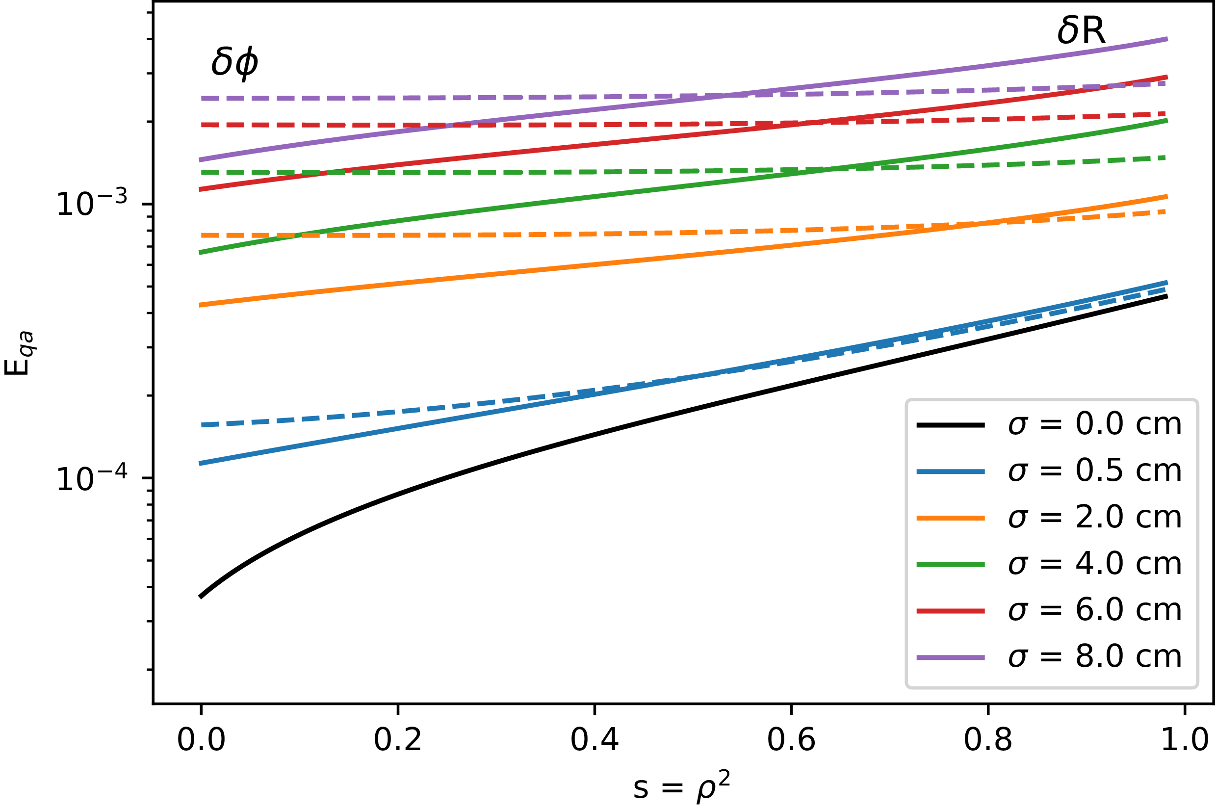
did not vary significantly from that calculated by truncating each series at 18.) Figure 2 shows the profile of
 $E_{qa}$
across the plasma calculated from the Fourier decomposition of
 $B$
for each of the eleven ARC ripple fields. It can be seen that the deviations from quasi-axisymmetry caused by toroidal misalignments are relatively constant across the plasma, while the deviations caused by radial misalignments are smaller near the axis, becoming dominant at
 $s=\rho ^2$
between 0.5 and 0.8, depending on the misalignment size.
Root-mean-squared deviations from quasi-axisymmetry are plotted from the axis to the plasma edge for ARC magnetic fields created from coil sets with two different misalignment types and five misalignment magnitudes.

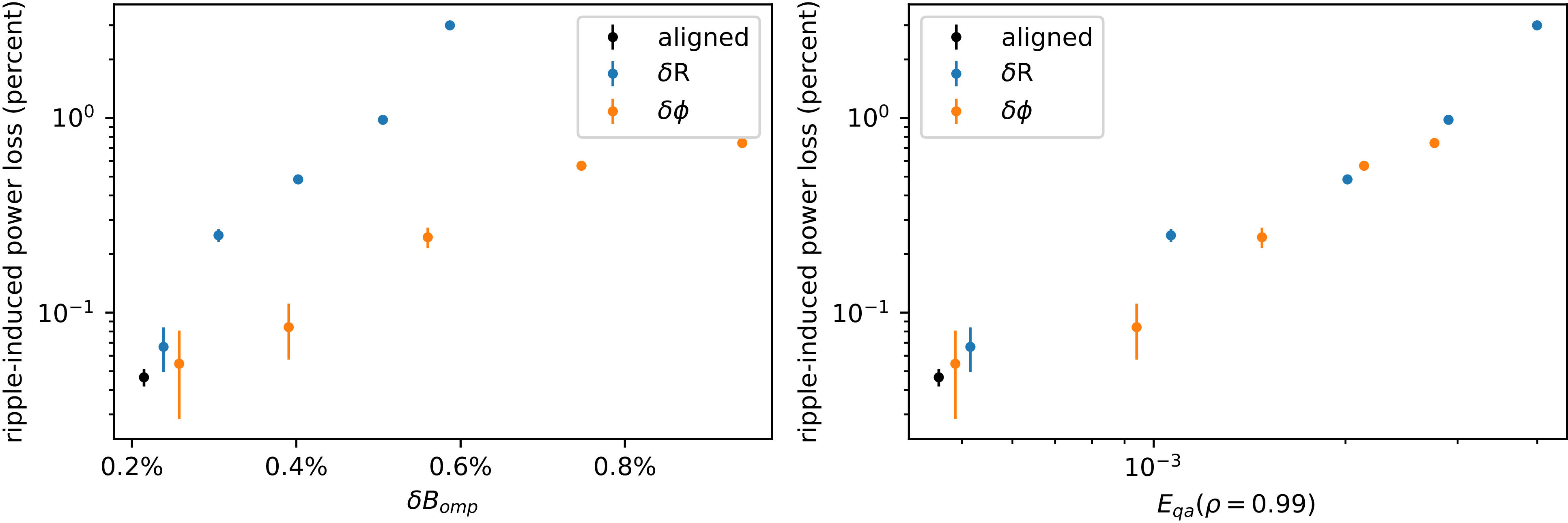
Figure 3 plots ripple-induced alpha power loss (with error bars calculated by bootstrapping) against the TF ripple at the outer midplane separatrix (
 $\delta B_{omp}$
, left) and
 $E_{qa}(\rho =0.99)$
(right). As in Hillesheim et al. (Reference Hillesheim2026), we chose to include all components of
 $B$
while calculating the ripple (defined as
 $\delta B= ({\max (B)-\min (B)})/({\max (B)+\min (B)})$
for a given
 $R$
and
 $Z$
), including
 $B_r$
and
 $B_z$
from both coil misalignments and the plasma contribution, and to take the maximum and minimum of the field strength over a full
 $360^\circ$
, rather than averaging over ripple wells. We see that, while
 $\delta B_{omp}$
correlates with alpha power loss for misalignments of a specific type, when radial and toroidal misalignments are compared, this metric cannot explain why radial misalignments lead to higher losses than toroidal misalignments with the same
 $\sigma$
. (While not shown, the same is true when considering only the
 $B_\phi$
component of TF ripple, when averaging
 $\delta B$
over the different ripple wells, or when taking a flux-surface average of
 $\delta B$
on the
 $\rho =0.99$
surface.) On the other hand, the relationship between
 $E_{qa}$
at
 $\rho =0.99$
in the different ripple fields for ARC and their ripple-induced alpha power loss is nearly monotonic; any non-monotonic behaviour is within the statistical error calculated for the loss. Unlike in previous studies of QA stellarators (LeViness et al. Reference LeViness, Schmitt, Lazerson, Bader, Faber, Hammond and Gates2023), the relationship found is not close to linear, but rather exponential.
(Left) The TF ripple at the outer midplane separatrix does not explain differences in ripple-induced losses between the two misalignment types. (Right) A nearly monotonic relationship is found between
 $E_{qa}$
(defined as the root-mean-squared sum of Fourier components of
 $B$
with
 $n\neq 0$
divided into the root-mean-squared sum of
 $n=0$
components) at
 $\rho =0.99$
and alpha power loss in ARC.

If
 $E_{qa}$
is averaged over more values of
 $\rho$
, as was done in previous work, the relationship weakens. Therefore, it is likely that, for tokamaks, which are close to axisymmetry and primarily lose particles which are born within the outer flux surfaces, it is the quasisymmetry of the field strength at the very edge which plays the biggest role in losses. Thus, it can likely be said that radial misalignments of ARC coils cause higher alpha losses than toroidal misalignments with the same misalignment
 $\sigma$
because they result in higher total amplitudes of non-QA components of the magnetic field strength at the edge of the plasma.
3.1. Additional misalignment types
Previous work on SPARC considered not only radial and toroidal misalignments, but also vertical shifts (‘up/down misalignments’) and vertical tilts (rotation of the TF coils around
 $\hat {R}$
). The latter were found to have negligible impact on (vacuum) TF ripple throughout the plasma, and therefore, these misalignments were not included when simulating alpha losses. Vertical shifts also had a negligible impact on vacuum ripple at the midplane, but well off the midplane (at Z = 0.5 and 0.75 m), the ripple induced was close to that from toroidal misalignments. Simulations of alpha loss were performed for SPARC with vertical coil shifts, and the alpha losses were found to be increased over the nominal case, but lower than the losses induced by toroidal and radial misalignments (Scott et al. Reference Scott2020).
Because toroidal and radial misalignments were expected, based on these results, to induce the highest losses, vertical shifts and tilts of the coils were not explored in the initial simulations performed for ARC. We attempt now to apply the metric of quasisymmetry error to fields created with these misalignment types in order to predict what alpha losses might be induced.
For each
 $\sigma$
and misalignment type, over one hundred coil sets were generated and one coil set representative of the mean was chosen using the same method as described in Hillesheim et al. (Reference Hillesheim2026). For the vertical tilt misalignments, the angle of rotation was calculated from the misalignment magnitude in m of
 ${\rm d}x$
as
 ${\rm d}\theta ={\rm d}x/Z_{max}$
, where
 $Z_{max}$
is the maximum height of the TF coil case for V3A, 5.7 m. The full 3-D magnetic field was then calculated, a Fourier decomposition was performed, and
 $E_{qa}$
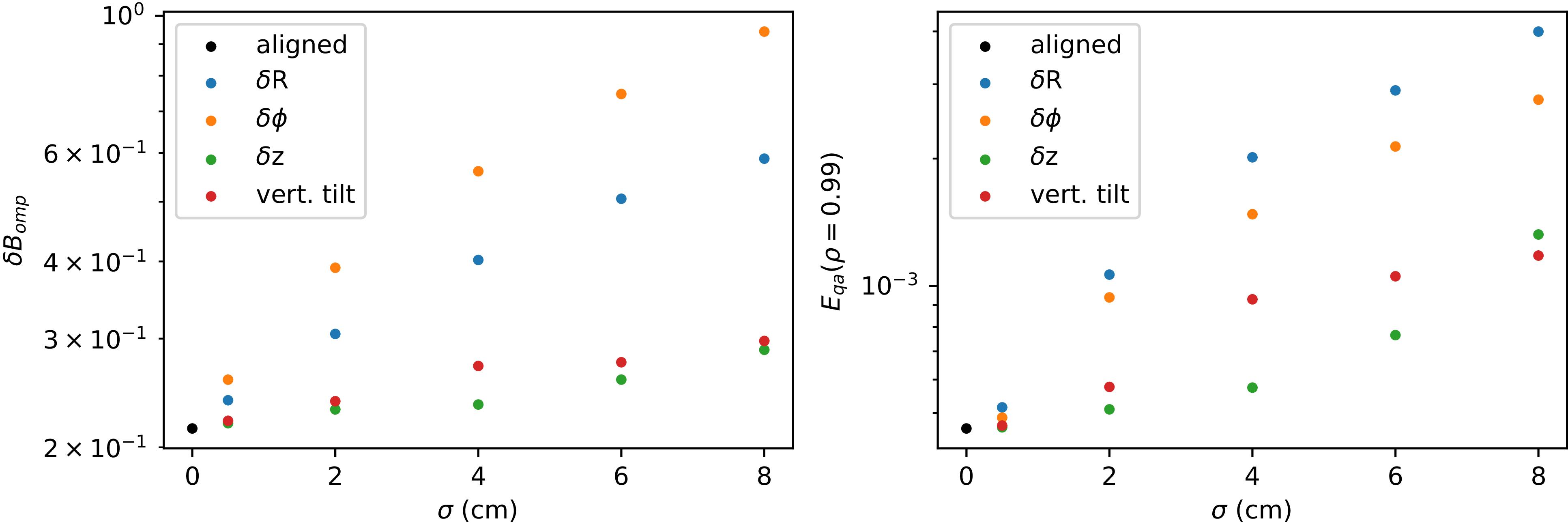
was determined. Figure 4 shows, for all four misalignment types (radial, toroidal and vertical shifts, and vertical tilts),
 $\delta B$
at the outer midplane separatrix (left) and
 $E_{qa}$
at
 $\rho =0.99$
(right) as a function of
 $\sigma$
.
The TF ripple at the outer midplane (left) and QA error at the
 $\rho =0.99$
flux surface (right) created by representative coil sets of 4 misalignment types and 5 misalignment
 $\sigma$
values, as well as by perfectly aligned coils.

Figure 4. Long description
Panel A: A scatter plot shows the change in toroidal field ripple at the outer midplane (delta B_omp) versus misalignment sigma (cm). The x-axis is labeled ‘sigma (cm)’ and ranges from 0 to 8. The y-axis is labeled ‘delta B_omp’ and ranges from 2 x 10^-1 to 10^0. Different colored dots represent aligned coils and various types of misalignments: delta R, delta phi, delta z, and vertical tilt. Panel B: A scatter plot shows the quasi-axisymmetry error (E_qa) at the flux surface versus misalignment sigma (cm). The x-axis is labeled ‘sigma (cm)’ and ranges from 0 to 8. The y-axis is labeled ‘E_qa (rho = 0.99)’ and ranges from 10^-3 to 10^0. Different colored dots represent aligned coils and various types of misalignments: delta R, delta phi, delta z, and vertical tilt.
The coil sets were selected based on calculated vacuum ripple, but the ripple value shown in figure 4 includes the plasma contribution. Unlike the previous two misalignment types, here there is a significant difference in
 $\delta B$
with and without including the plasma contribution to the field; while it is not shown here, the additional vacuum ripple at the midplane induced by each of these misalignment types is negligible, as found in Scott et al. (Reference Scott2020). Because of this, we find that
 $\delta B_{omp}$
does not increase as evenly with
 $\sigma$
for the case of vertical shifts and tilts as compared with other misalignment types, as the coil sets selected are poorer approximations of the average
 $\delta B$
produced by each misalignment
 $\sigma$
.
Most interestingly, we see that vertical tilts and vertical misalignments produce a similar
 $\delta B_{omp}$
for most values of of misalignment
 $\sigma$
, and the vertical tilts induce a larger
 $E_{qa}$
for the middle three
 $\sigma$
values. This suggests that the decision to exclude this misalignment type from the simulations in Scott et al. (Reference Scott2020) may have been erroneous, and that despite inducing little vacuum TF ripple, vertical tilts of the coils could cause significant alpha losses, although still less than radial and toroidal misalignments. In order to investigate this, two additional ASCOT5 simulations were performed, each following 8192 markers born outside
 $\rho =0.65$
for 150 ms, in fields calculated from the
 $\sigma =8$
cm coil sets chosen for both vertical shifts and vertical tilts.
Based on the previous results, we expect the ripple-induced power loss to be between 0.24 % and 0.25 % for both the vertical misalignment and the vertical tilt cases. However, the ASCOT5 simulations give ripple-induced losses of
 $1.46\pm 0.04\%$
and
 $3.46\pm 0.06\%$
, respectively – 6 and 14 times higher, respectively, than the losses predicted by QA error, and the losses are higher in the vertical tilt case despite
 $E_{qa}(\rho =0.99)$
being slightly lower. The fact that the losses from vertical shifts exceed those from toroidal misalignments at the same
 $\sigma$
also does not match the results from SPARC shown in Scott et al. (Reference Scott2020), although that work only simulated non-toroidal misalignments at one value of
 $\sigma$
each, and it is possible that the losses from vertical shifts grow more rapidly with increasing
 $\sigma$
than those from toroidal misalignments.
What is the cause of the higher-than-expected ripple losses induced by vertical shifts and tilts of the coils in ARC? It is not explained by either TF ripple or QA error, as both metrics (including both vacuum TF ripple and the ripple of the full, finite-
 $\beta$
field) are significantly lower across the entire plasma for these two new misalignment types compared with the previous two.
Examining these misalignment types further, we find that there is a significant difference in the poloidal mode number of the perturbations they introduce in the magnetic field strength. Considering the case of each misalignment with the largest
 $\sigma$
and looking at the
 $\rho =0.99$
flux surface, we find that, for the toroidal misalignments, 96 % of the QA error comes from
 $m=0$
modes, while for the radial misalignments, 40 % comes from these modes, and for the vertical shifts and tilts, only between 5 % and 7 % comes from
 $m=0$
modes.
We can also look for modes in the perturbed field which resonate with rational surfaces in the plasma. The minimum
 $q$
in the field used in this paper (which, again, excludes the plasma contribution to
 $B_\phi$
, and thus differs from the 2-D equilibrium field reported in Hillesheim et al. Reference Hillesheim2026) is 0.86, and it reaches a value of around 3.23 near the edge. Considering only modes with
 $0.86\leqslant m/n\leqslant 3.23$
, we find they make up 1 % of the QA error for the radial misalignments, 0.2 % for the toroidal misalignments and 3 % for both the vertical shifts and tilts. Examining Poincaré plots of these magnetic fields, generated with ASCOT5, it can be seen that, in fact, all misalignment types but the toroidal case see significant stochasticity in the edge, usually beginning near or past the
 $3/2$
flux surface.
This may be a limit of the methods used in this work, as in reality, the plasma would heal some of this stochasticity, as well as the large islands produced by the misalignments. The choice to assume 2-D flux surfaces and treat the ripple as a small perturbation may not be valid for such large misalignments. An analysis which recalculates the equilibrium field in three dimensions before calculating the TF ripple and quasisymmetry error would likely produce more reliable results, but is beyond the scope of this work. We can, however, consider here an adjusted form of
 $E_{qa}$
which only takes into account those modes in which
 $m/n$
is within a certain range.
Additional ASCOT5 simulations were performed to simulate losses induced by vertical misalignments and tilts at two additional
 $\sigma$
, considering
 $\sigma =[0.5,4]$
cm in addition to the 8 cm cases already considered. The same
 $\rho _{min}$
was used, and either 24 576 markers (for the
 $\sigma =0.5$
cm case, as more markers were needed to resolve the relatively small increases in losses) or 8192 markers (for the
 $\sigma =4$
cm case) were followed for 150 ms. For all equilibria simulated, a new version of
 $E_{qa}$
was calculated
 \begin{align} E_{qa,adjusted}(\rho ) = \frac {\sqrt {\sum _{n\neq 0,m/n \geqslant q_{min}}B^2_{m,n}(\rho )}}{\sqrt {\sum _{n=0,m}B^2_{m,n}(\rho )}}. \end{align}
Here,
 $q_{min}$
was allowed to vary between 0.86 and 2, and it was found that the strongest correlation between
 $E_{qa,adjusted}(\rho =0.99)$
and loss was produced by
 $q_{min}=1.6$
, which seems reasonable considering that the majority of the stochasticity is seen outside the
 $3/2$
surface. The upper limit of
 $q$
did not impact the results, as the modes with high
 $m/n$
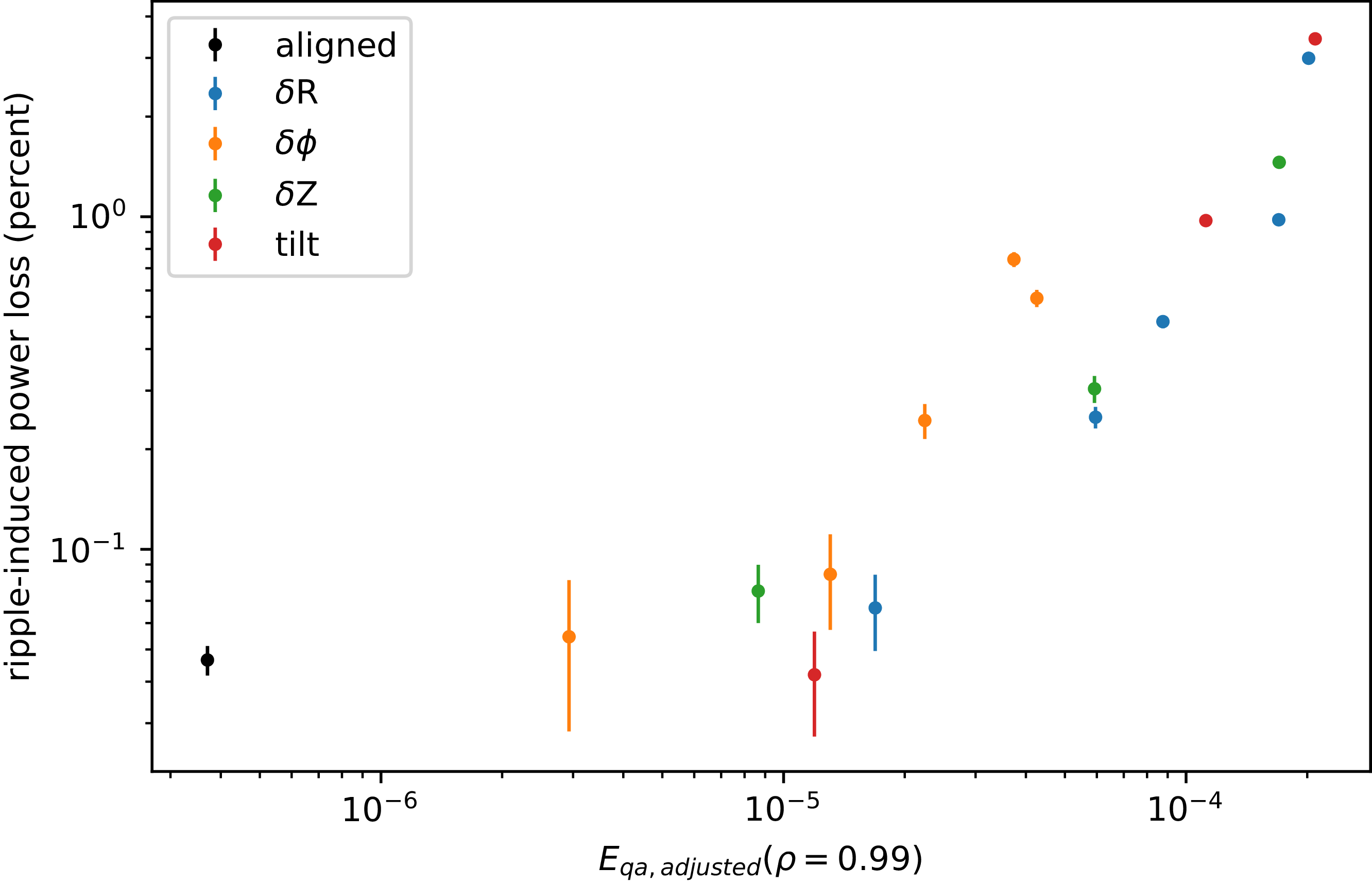
were relatively small, so no upper limit was set. The results are plotted in figure 5; it can be seen that this adjusted version of
 $E_{qa}$
has a nearly monotonic relationship with losses for the radial shifts and vertical shifts and tilts, but under-predicts the losses from toroidal misalignments.
Ripple-induced losses, with bootstrapped error bars, plotted against an adjusted form of QA error at the
 $\rho =0.99$
flux surface which only considers components of the field strength with
 $m/n\geqslant 1.6$
.

This tells us that variations in fast ion losses in these fields with strongly misaligned coils are likely determined by a combination of ripple-induced modes in the field strength
 $B$
which resonate with the safety factor profile of the base equilibrium near the edge of the plasma, causing stochastic transport of the alphas, and
 $m=0$
modes in
 $B$
which contribute to ripple trapping and banana tip diffusion. However, an analysis including the plasma response may heal some of the stochasticity, changing the flux surfaces, the QA error and the resulting losses. Thus, the adjusted
 $E_{qa}$
can be thought of less as a proxy for losses than as a diagnostic for understanding at which point the traditional metric of QA error is not applicable due to stochasticity.
4. Application to SPARC
Next, we will apply this method to misaligned coil sets for SPARC, which is in a more advanced stage of its design and thus has more information on alignment tolerances. Assuming the TF coils designed for SPARC move as rigid bodies, the following constraints are applied. First, coils are not allowed to move in the
 $\hat {Z}$
(vertical) direction, as alignment is expected to be precise in this direction. Next, a line segment is defined in cylindrical coordinates
 $(R,\phi ,Z)$
by the two points
 $P_{1a}=(R_1, ({n\pi })/{9},-Z_1)$
and
 $P_{1b}=(R_1,({n\pi })/{9},+Z_1)$
, where
 $n\in [0,17]$
is the TF coil index,
 $R_1$
is the innermost radial point of the TF coil case and
 $Z_1=1.21$
m.
To determine the position and tilt of the coil,
 $P_{1a}$
and
 $P_{1b}$
are allowed to move by up to
 $\pm 2$
mm in both
 $\hat {R}$
and
 $\hat {\phi }$
as defined at the nominal coil position. During this process, the additional point
 $P_2=(R_2,({n\pi })/{9},0)$
, where
 $R_2$
is the outermost radial position of the TF coil case, is held at constant
 $\phi$
, although it is allowed to shift radially and vertically as is necessary to maintain the rigid shape of the coil. Finally, after misaligning points
 $P_{1a}$
and
 $P_{1b}$
,
 $P_2$
is allowed to move by
 $\pm 1$
mm by rotating the outer leg of the coil around the midpoint of the line segment between
 $P_{1a}$
and
 $P_{1b}$
. This process provides a somewhat conservative estimate of possible misalignments, as more recent work on SPARC assembly tolerances suggests that the inner leg will be more tightly constrained in the toroidal direction than in this work.
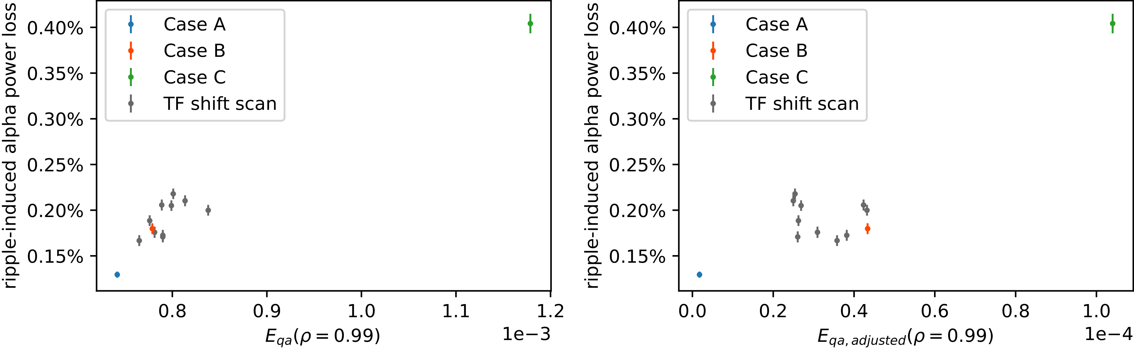
Several rippled magnetic fields were created and used in simulations for SPARC. These include fields designated ‘case A,’ ‘case B’ and ‘case C,’ which were chosen to represent best, median and worst case coil sets, and a group of fields from 10 additional coil sets spanning different ripple magnitudes.
Case A has perfectly aligned TF coils and therefore the lowest possible ripple. Case C, an attempt at finding the worst case coil set (within the given tolerances), was constructed as follows: for coils
 $n\in [0,8]$
,
 $P_{1a}$
,
 $P_{1b}$
and
 $P_2$
were shifted the maximum allowed extent in
 $-\hat {\phi }$
(as defined at the nominal coil position). For coils
 $n\in [9,17]$
,
 $P_{1a}$
,
 $P_{1b}$
and
 $P_2$
were shifted the same displacement magnitude in
 $+\hat {\phi }$
, thus bringing the coils closer together where the two halves meet and creating an
 $n=1$
perturbation in field strength. The coils were also shifted inward and outward radially in two consecutive groups of 9 to the maximum extent allowed, with the point of division chosen to maximise coil ripple at both the axis and the outer midplane separatrix. The coils were not tilted due to the previous work showing low impact of vertical tilts on TF ripple in SPARC (Scott et al. Reference Scott2020). The results of § 3.1 suggest that this may cause an underestimate of maximum possible losses, but as we will see later in this section, even excluding vertical tilts, case C produces much higher losses than seen from any plausible random selection of coil misalignments.
To select both case B and the group of 10 additional coil sets, we began with 200 coil sets randomly generated by randomly generating
 $200 \times 18 \times 5$
values, for 200 sets of 18 coils with 5 different degrees of freedom (misalignments of
 $P_{1a}$
and
 $P_{1b}$
in
 $\hat {R}$
and
 $\hat {\phi }$
, and rotations of
 $P_2$
). Each value was randomly selected within the previously described limits for the motion. Using a simplified model of the coil structure, the vacuum TF ripple was calculated at two radial locations: the axis and the outer midplane separatrix.
A value defined as
 \begin{align} \delta _i=\frac {\delta B(Z = 0, R = R_i) - \mu _{\delta B_i}}{\sigma _{\delta B_i}}, \end{align}
where
 $i$
is each radial location,
 $\mu _{\delta B_i}$
is the mean value of ripple
 $\delta B$
at this location for the sample of coil sets and
 $\sigma_{\delta B_i}$
is the standard deviation, was calculated for each of the 200 coil sets in the sample and each of the two radial positions. Next, the quantity
 $\delta _{1}=\sum _i^2{|\delta _i|}$
was calculated for each coil set, serving as an approximation for the overall ripple magnitude created by the misalignments. Case B was selected as a coil set with
 $\delta _{1}$
very near 0; that is, it was expected to have TF ripple very close to the mean of the sample of coil sets. The additional 10 coil sets for the scan were selected from the 200 by first calculating
 $\delta _2=\sum _i^2{\delta _i}$
, then minimising
 $|\delta _2(n)-(\min (\delta _2)+ ({i}/{9})(\max (\delta _2)-\min (\delta _2)))|$
, where
 $i$
is an integer ranging from 0 to 9. In this way, 10 coil sets with nearly evenly spaced
 $\delta _2$
spanning the range of the sample were selected. (For this sample,
 $\delta _2$
ranged from –4.28 to 5.64.)
For each of these 13 magnetic fields, ASCOT5 simulations were performed to find the alpha power crossing the LCFS. The kinetic profiles used in these simulations were those of the SPARC primary reference discharge (PRD), published in the SPARC physics basis (Rodriguez-Fernandez et al. Reference Rodriguez-Fernandez, Howard, Greenwald, Creely, Hughes, Wright, Holland, Lin and Sciortino2020) and the public SPARC repository (Creely et al. Reference Creely2020b
), while the equilibrium used was a high-fidelity equilibrium calculated by a script developed internally by CFS, and was nearly identical to the SPARC PRD equilibrium published in Creely et al. (Reference Creely2020a
), also included in the repository. Multiple simulations were performed for different coil sets, with
 $\rho _{min}$
ranging from 0.6 to 0.74, and maximum simulation times ranging from 45 to 50 ms, chosen again to capture nearly all lost alpha power within the simulation. The total number of markers simulated was 1179 648 for case A, 262 144 for case B and the 10 additional coil sets and 131 072 for case C. An additional simulation was performed, following 131 072 markers born outside
 $\rho _{min}=0.74$
for 50 ms in an axisymmetric version of the SPARC PRD, to determine the non-ripple losses. In all simulations, the markers were weighted by the alpha birth profile calculated from the kinetic profiles.
The axisymmetric alpha losses predicted for the SPARC PRD in these simulations was
 $1.867\pm 0.009$
%, with the error again estimated by bootstrapping. This is significantly lower than the 2.8 % reported for an older version of the SPARC equilibrium, V1E (Scott et al. Reference Scott2020). The difference is primarily due to a change in safety factor profile and flux-surface shapes, as well as changes in how the markers were initialised. In reality, of course, alpha losses in SPARC will span a range of values depending on the actual equilibrium and profiles realised.
Figure 6 shows the ripple-induced alpha power loss, calculated again as the difference between losses found in the 3-D and 2-D simulations, plotted against
 $E_{qa}$
(left) and
 $E_{qa,adjusted}$
(right) evaluated at
 $\rho =0.99$
for each of these 13 equilibria, with errors estimated via bootstrapping. We can see that, due to the tight assembly tolerances of SPARC, both
 $E_{qa}$
(in the original and adjusted forms) and the ripple losses span significantly smaller ranges of values than those found for ARC, in which larger coil misalignments were simulated. It is also clear that the original definition of
 $E_{qa}$
proves a better proxy for losses than the adjusted version, as due to the smaller magnitude of the misalignments relative to the machine size, there is not appreciable stochasticity introduced in any of the ripple fields but case C, and even then, it is only at the very outermost flux surfaces.
Quasi-axisymmetry error (left) or adjusted QA error (right) near the plasma edge and ripple-induced alpha power loss are compared for thirteen different possible coil sets for SPARC, with error bars calculated by bootstrapping. A nearly linear relationship is found with the original
 $E_{qa}$
.

This shows that, for TF misalignments which are small enough that the ripple field can be taken as a small perturbation on top of the underlying equilibrium, QA error as typically defined in stellarator theory serves as a useful proxy for fast ion losses, while for larger misalignments, it may be necessary to include the plasma response before calculating QA error or any other proxy. While the relationship between
 $E_{qa}$
and loss in SPARC is not monotonic, it is nearly linear; calculated across all 13 data points in figure 6 (left), Pearson’s correlation coefficient is 0.97 – higher even than the correlation between
 $E_{qa}$
averaged over different volumes of the plasma and alpha power loss found in LeViness et al. (Reference LeViness, Schmitt, Lazerson, Bader, Faber, Hammond and Gates2023).
It can also be seen that, as previously stated, even without allowing for coil tilts, case C is far beyond even the worst of the randomly selected coil sets in both
 $E_{qa}$
and loss – meaning that, if assembly tolerances are adhered to, we expect case C to set a conservative upper limit for
 $E_{qa}$
, TF ripple, alpha losses and power loads to the PFCs, particularly as, in reality, some of the ripple-induced stochasticity in the case C field may be healed by the plasma.
The model of the SPARC TF coils used in this work is not perfectly identical to the final engineering design of the coils; it is slightly simplified on the outer leg and shifted radially outward by 1.3 cm. An additional 6 mm of difference in radial position between our model and the expected coil position is added when comparing with the TF coils at operating temperature and current. A simulation was also performed for the final coil design at their predicted operating position (although not shrunk slightly, as will be the case in operation), with perfectly aligned coils, and the alpha power loss was found to be only 0.04 % lower (a 2 % variation in the power loss value) than that found with the case A field in this work. Thus, we can say that the coil model used here results in a close, slightly conservative, estimate of losses from the true TF design.
5. Comparison with near-QA stellarator equilibria
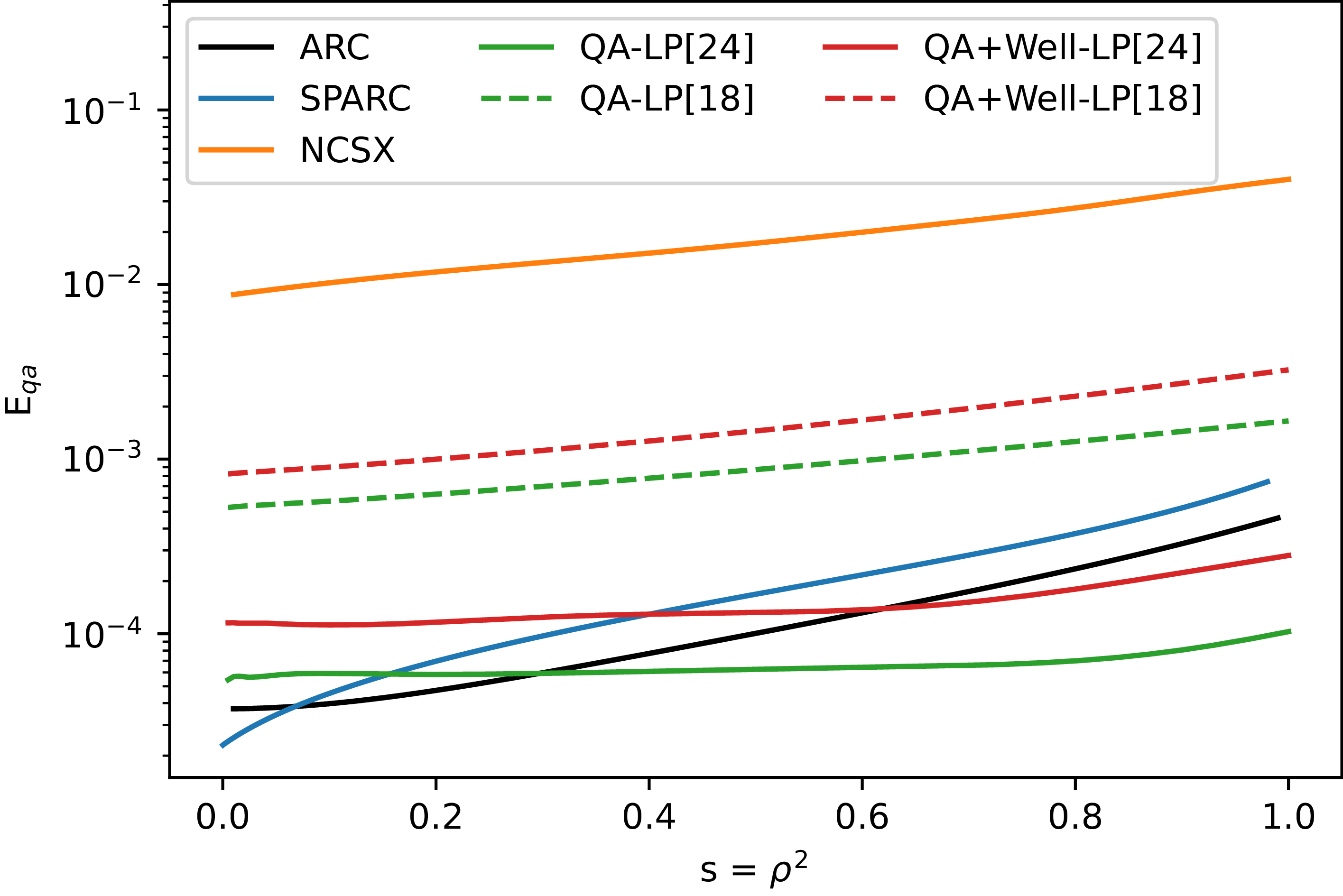
Finally, we ask, how do rippled tokamak equilibria compare with near-QA stellarator equilibria? Does it make sense to analyse rippled tokamaks using methods developed for QS stellarators? Figure 7 shows
 $E_{qa}$
across the plasma for ARC and SPARC with perfectly aligned coils, as well as for several QA stellarator designs. The first is the free-boundary NCSX equilibrium, derived from the publicly available coil set designed for the partially constructed stellarator. The remaining four are variations on the Landreman–Paul QA designs (Landreman & Paul Reference Landreman and Paul2022), with (‘QA + Well-LP’) and without (‘QA-LP’) a Mercier stable magnetic well, as approximated by different sample coil sets in Wechsung et al. (Reference Wechsung, Landreman, Giuliani, Cerfon and Stadler2022). Assuming a major radius of 1 m and a set of 16 coils composed of 4 unique coil designs repeated 4 times, the coil sets were optimised while setting the upper limit
 $L_{max}$
on the combined length of the 4 unique coils to either 18 or 24 m. (In comparison, the average filament in the SPARC coil representation used here is 10.8 m; the ratio of average coil length to major radius for SPARC is thus 5.9, in between the values of 4.5 and 6 for the QA coil sets.)
It can be seen that the QA error in ARC and SPARC is significantly lower (by factors of between 1/54x and 1/380x) than that of NCSX across the entire plasma; while cases B and C for SPARC are not plotted here, they also have more than an order of magnitude lower
 $E_{qa}$
across the entire plasma than NCSX, showing that even with the worst misalignments within assembly tolerances, a rippled tokamak like SPARC is still significantly more QS than a moderately optimised QA stellarator like NCSX. However, depending on the coil length assumed, the Landreman–Paul QA designs may achieve more precise quasi-axisymmetry than ARC and SPARC across the outer half of the plasma volume.
The QA error across the entire plasma is plotted for ARC and SPARC with perfectly aligned coils, as well as for optimised QA stellarators, including NCSX (free boundary) and variations on the Landreman–Paul QA configurations (Landreman & Paul Reference Landreman and Paul2022) with optimised coil sets of varying length (Wechsung et al. Reference Wechsung, Landreman, Giuliani, Cerfon and Stadler2022).

This is not to say that we can thus assume that highly optimised QS stellarators will outperform tokamaks in fast ion confinement. As previously stated, quasisymmetry error cannot necessarily be used to predict fast ion losses across different device types, as there are additional factors which determine confinement, such as magnetic shear, device size and plasma density and temperature. In addition, there are no experimental results proving that QS stellarators can achieve the very low fast ion losses predicted by simulation, while there are a wide range of experimental results validating predictions of neoclassical fast ion confinement in tokamaks (Manos et al. Reference Manos, Budny, Satake and Cohen1982; Tuszewski & Roubin Reference Tuszewski and Roubin1988; Zweben et al. Reference Zweben, Boivin, Diesso, Hayes, Hendel, Park and Strachan1990; Tobita et al. Reference Tobita, Tani, Neyatani, van Blokland, Miura, Fujita, Takeuchi, Nishitani, Matsuoka and Takechi1992; Boivin, Zweben & White Reference Boivin, Zweben and White1993; Heidbrink & Sadler Reference Heidbrink and Sadler1994; Huynh et al. Reference Huynh, Lerche, Eester, Artaud, Dumont, Maget and Moiraf2026).
Even if it were taken as a given that these stellarator designs could achieve very high fast ion confinement, we are comparing apples with oranges: the SPARC case A field is calculated from a close approximation of the actual engineering design for the SPARC TF coils, while the Landreman–Paul QA configurations shown are theoretical single-filament coil designs optimised to best approximate the QA-LP and QA + Well-LP equilibria. As-built stellarators, which must also consider engineering feasibility and other qualities, such as neutron shielding in power plants, may not be able to achieve such precise quasisymmetry. In addition, as coils can never be perfectly constructed or assembled, the question remains whether misalignments and other deviations from design in stellarator coils will be more or less deleterious for particle confinement than in tokamaks. Tokamaks also have the advantage of being able to run a variety of plasma equilibria, all of which will likely have similar levels of quasisymmetry if using the same coil set, while highly optimised stellarators are typically designed to achieve strong quasisymmetry with one specific set of coil currents and plasma pressure.
Regardless, it has been shown that tokamaks constructed from discrete coil sets lie between moderately and highly optimised QA stellarators when it comes to deviations from perfect quasisymmetry across much of the plasma – particularly the edge, from which fast ions tend to be lost – and that metrics used in stellarators to quantify quasisymmetry and optimise fast ion confinement can also be used to characterise alpha losses from tokamaks with realistic coil misalignments. Considering this, physically constructed, as opposed to idealised, tokamaks can be considered to be a special case of near-QA device, and there may be additional techniques from stellarator theory which can be applied to their design and simulation.
6. Conclusions
In this work, it was found that 3-D ripple fields created by the discrete TF coils and possible assembly errors in SPARC and ARC can be analysed with the metric of quasisymmetry error, often used as a proxy for fast ion losses in stellarators, and that this metric strongly correlates with loss of alpha power in these two tokamaks, other than in the case of large vertical shifts or tilts of the TF coils. In this latter case, an adjusted form of
 $E_{qa}$
which includes only those modes in the field strength which resonate with the safety factor near the edge serves as a better proxy for loss.
However, the misalignments considered for ARC in this paper are far outside expected tolerances. For the fields considered for SPARC, in which misalignments were limited based on assembly tolerances, the traditional form of
 $E_{qa}$
predicted alpha power loss with a correlation coefficient of 0.97. This shows that, for relevant cases, the simple form of
 $E_{qa}$
should serve as a strong proxy for losses in rippled tokamaks, while the adjusted version mostly serves as a diagnostic for determining which fields will become stochastic in the edge and therefore require a more rigorous treatment.
It was also shown that even with perfectly aligned TF coils, SPARC and ARC have similar or higher values of QA error to highly optimised QA stellarators with simple coil designs, justifying the decision to treat these rippled tokamak equilibria as a special case of near-QA devices.
The work shown in this paper did not consider the impact of RMPs, although both SPARC and ARC will contain coils capable of inducing RMPs if needed for ELM suppression (Sweeney et al. Reference Sweeney2020; Leuthold et al. Reference Leuthold2026). If the 3-D fields induced by these coils are found to break QA severely enough in the plasma edge for the field in this region to become stochastic, then another metric may be more appropriate for the analysis of equilibria with applied RMPs. In addition, if the use of RMPs is found to be necessary in future devices like ARC, and the QA error induced by these perturbations is large compared with error fields from TF coil misalignments, it may be possible to relax tolerances on TF coil alignment without significantly worsening alpha losses – although this does not consider other negative impacts of misaligned TF coils.
There may also be additional metrics which, while more complicated to compute than QA error, better characterise losses. For instance, there are the metrics
 $\varGamma _C$
and
 $\varGamma _\alpha$
, sometimes used in stellarator optimisation, which attempt to more directly quantify the omnigeneity of a given field (Nemov et al. Reference Nemov, Kasilov, Kernbichler and Leitold2008; Velasco et al. Reference Velasco, Calvo, Mulas, Sánchez, Parra and Cappa2021). In addition, it has been shown that a significant driver of losses is the resonance between field asymmetries and the ‘orbit pitch’ of the fast ion orbits (rather than the field line pitch, which is considered in the modified
 $E_{qa}$
used in this paper), which breaks conservation of the second adiabatic invariant and, in the case of multiple overlapping resonances, can drive the fast ion orbits to become stochastic.
This effect is especially relevant to RMPs in tokamaks, which have been shown to drive losses of fast ions in KSTAR and EAST due to resonant interactions with the ion orbits (Shinohara et al. Reference Shinohara, Bierwage, Suzuki, Kim, Matsunaga, Honda and Rhee2018; He et al. Reference He, Sun, Liu and Wan2025). It has been discussed in Chambliss, Paul & Hudson (Reference Chambliss, Paul and Hudson2025) that even small deviations from quasisymmetry in stellarators can lead to increased losses when these errors are resonant with fast ion drift orbits, and simulated alpha losses from the Helios stellarator design have been characterised based on this resonance (von der Linden et al. Reference von der Linden, Labbate, Paul, Flom, Dudt, Wu, Kruger, Swanson, Kumar and Gates2026). A further modified version of
 $E_{qa}$
which considers deviations from QA resonant with the alpha drift orbits, rather than with the safety factor near the edge, may better explain alpha losses, as might a metric which quantifies the width or overlap of alpha drift islands, as explored in Shinohara et al. (Reference Shinohara, Bierwage, Suzuki, Kim, Matsunaga, Honda and Rhee2018). However, this more complicated analysis, which requires the energy and pitch of the alphas to be taken into account, is left for future work.
While QA error is insufficient for predicting losses between significantly different devices, or in cases where coil misalignments are very large and fields become stochastic, it correlates well with losses across variations on a specific device when misalignments are not too large. The calculation of QA error requires only the calculation of the ripple field on a 3-D grid and a simple analysis, which is much less computationally expensive than Monte Carlo orbit-following simulations to determine alpha losses – once the 3-D field is calculated, finding the QA error takes only a few minutes on a single CPU, while the ASCOT5 simulations required around 10 CPU node hours on Perlmutter for the smallest simulations performed for ARC in this paper and 80 for the largest. This suggests that, as in stellarator optimisation, QA error may be used as a proxy for ripple-induced alpha loss in tokamaks for rapid design iterations of TF coils and evaluation of the impact of different potential assembly errors – one which is faster and simpler than full orbit-following simulations and more accurate than the traditional tokamak metric of TF ripple.
Acknowledgements
The authors would like to thank the members of the ASCOT group based at Aalto University and VTT Technical Research Centre of Finland for allowing use of their code ASCOT5 and for their support of this work. All simulations were performed using ASCOT version 5.5.6. The authors would also like to thank Elizabeth Paul at Columbia University for her help interpreting the results, Matt Landreman at the University of Maryland for providing the Boozer spectra for the four QA-LP configurations and Ken Hammond at Princeton Plasma Physics Laboratory for assistance in calculating the Boozer spectrum for NCSX. The free-boundary NCSX input file can be found at https://princetonuniversity.github.io/STELLOPT/VMEC in the tutorials section, under ‘Free Boundary Run for NCSX-like configuration’.
Editor Per Helander thanks the referees for their advice in evaluating this article.
Funding
This work was funded by Commonwealth Fusion Systems. The information, data or work presented herein builds on the ARC V3A equilibrium as well as the SPARC PRD and X-point target discharge data, both provided by Commonwealth Fusion Systems. This material is based upon work supported by the U.S. Department of Energy, Office of Science, Fusion Energy Sciences, under the Milestone-Based Fusion Development Program under Award Number DE-SC0024885. This research used resources of the National Energy Research Scientific Computing Center, a DOE Office of Science User Facility supported by the Office of Science of the U.S. Department of Energy under Contract No. DE-AC02-05CH11231 using NERSC awards FES-ERCAP0032045, FES-ERCAP0032161, FES-ERCAP0037319 and FES-ERCAP0037380.
Declaration of interests
The authors report no conflict of interest.

 B
 ρ=0.99
 Eqa
 B
 n≠0
 n=0
 ρ=0.99
 ρ=0.99
 σ
 ρ=0.99
 m/n⩾1.6
 Eqa

 Open access

