1. Introduction
Identification of position and orientation parameters of specific objects is a crucial task in machine vision. 3D cameras generate point clouds containing pose information of structured objects, with measurement and character identification being the primary functions of 3D vision.
Stereo vision, a type of 3D imaging system, captures information simultaneously from different views, containing 3D object information. Stereo vision styles include monocular vision [Reference Song1–Reference Lu, Zhou, Li, Ju, Tan and Duan4], binocular vision [Reference Zimiao, Kai, Yanan, Shihai and Yang5–Reference Zhao and Allison9], and multiview stereo vision [Reference Chen and Cui10–Reference Liu12], the latter being a more complex binocular variant.
RGB-D cameras, typically based on binocular vision principles [Reference Duan and Zhang13, Reference Long14], are widely used in robots [Reference Kim, Kang, Kang and Kim15, Reference Shen, Lin, Xu, Zhou and Wang16], drones [Reference Backman, Kulic and Chung17, Reference Santos, Santana, Brandao and Sarcinelli-Filho18], industrial production [Reference Back, Kim, Kang, Choi and Lee19, Reference Damen, Gee, Mayol-Cuevas and Calway20] and more. Although their refresh rate is sometimes lower than LiDAR, RGB-D systems offer color information, providing additional scene details while remaining low-cost and easy to set up.
Construction robots often encounter plane identification problems, such as those found in wall painting robots [Reference Sorour, Abdellatif, Ramadan and Abo-Ismail21], floor surface profiling robots [Reference Wilson, Potgieter and Arif22], ground plane detection [Reference Chen, Zhou and Chu23–Reference Guo25], and surface reconstruction [Reference Fotsing, Menadjou and Bobda26, Reference Ryu, Oh, Kim, Cho, Son and Kim27]. Methods for plane extraction and parameter identification include random sample consensus (RANSAC) and its variants. PCL-RANSAC, a RANSAC-based method [Reference Rusu and Cousins28] offers a mature and stable plane identification algorithm [Reference Fotsing, Menadjou and Bobda26].
In quantitative applications, identification precision is of utmost importance. Some measurements of RGB-D cameras are known to have biased errors [Reference Neupane, Koirala, Wang and Walsh29–Reference Bung, Crookston and Valero32], but a priori information can be adopted to increase accuracy [Reference Parvis33]. A priori information is obtained from other sources but not by current measuring instruments.
Calibration methods collect a priori information for reducing the measurement error. Zhang [Reference Zhang34] reported a camera calibration method that models radial lens distortion. Darwish et al. [Reference Darwish, Li, Tang, Wu and Chen35] proposed a method to calibrate each error source of the RGB-D camera. Li et al. [Reference Li, Li, Darwish, Tang, Hu and Chen36] introduced a calibration method for plane fitting by constructing a plane fitting error model on an RGB-D system. Feng et al. [Reference Feng37] proposed a high-precision method for identifying petroleum pipeline interfaces by using camera calibration. Fuersattel et al. [Reference Fuersattel, Placht, Maier and Riess38] presented a calibration algorithm based on the least squares method to increase the plane fitting precision. However, these calibration methods rely on specific error models and do not use the same detected objects in application, leading to potential discrepancies between calibration and application environments that may cause unpredictable errors.
Interpolation methods can effectively fit unknown models if sample points are accurate. Mechanical measurement methods are typically reliable and precise, with high-precision encoders ensuring platform accuracy. However, these methods often depend on a particular camera distortion model to obtain sufficiently accurate sample points. This article proposes an interpolation-based calibration method that is independent of any specific distortion models, addressing exiting limitations. The method involves gathering accurate pose mapping rules offline and then applying these relations for pose correction during online use. Although initial pre-gathered relations are discrete in pose space, a continuous mapping relation is formed using interpolation. The method is ultimately applied to a construction robot to validate its improved precision in brick placement on a wall.
2. Calibration method proposition
2.1. Overview of plane pose correction
Suppose there is a bad-plane-pose space, which includes low-precision plane poses identified by a general algorithm from a stereo system, and a fine-plane-pose space, which includes all accurate poses of the actual plane. The main idea of the proposed calibration method is to find a single mapping from the bad-plane-pose space to the fine-plane-pose space. Furthermore, for generality, the method should accommodate situations where pose errors are irregular. Here, the pose error represents the difference between the plane pose in the bad-plane-pose space and its corresponding pose in the fine-plane-pose space.
Errors can be approximately regular within local subspaces, while global errors are irregular. Interpolation equations are derived within local subspaces to build the mapping from the initial plane pose to the accurate plane pose. A segmentation strategy is proposed for the entire space to obtain a group of subspaces.
Accurate interpolation points are required for building precise mapping relations. A high-precision mechanical platform is designed for gathering accurate data, and its geometry is analyzed. Accurate plane poses are obtained using a region-of-interest method that takes the geometry of the mechanical platform into account.
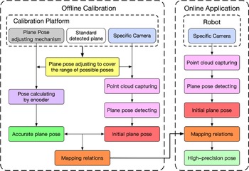
The flowchart of applying the proposed method is shown in Fig. 1.
Flowchart of using calibration methodology.

The method comprises two parts: offline calibration and online application, as shown in Fig. 1. In offline calibration, the camera to be used in the online scenario is fixed on the calibration platform. The platform can adjust the relative plane pose between the camera and the plane sample. By pairing initial plane poses and accurate plane poses, mapping relations are formed as a result of the offline calibration. In the online application, after obtaining the initial plane pose using conventional methods, the mapping relations correct the pose to a high-precision one. The procedures to obtain the initial plane pose for both offline and online identification should be the same.
2.2. Mapping from a bad-plane-pose space to the fine-plane-pose space
2.2.1. Plane pose mapping relations
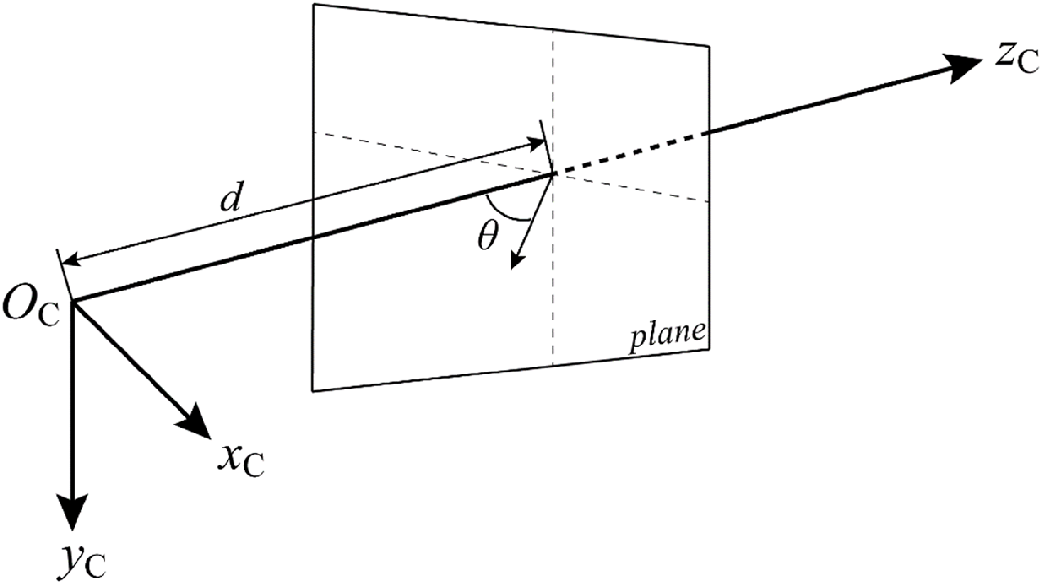
In this article, the issue of plane detection is examined within the camera coordinate system, as illustrated in Fig. 2. The camera coordinate system is constituted by a right-handed Cartesian coordinate system, with its origin
 $O_{\mathrm{C}}$
situated at the camera’s center. The z-axis extends from
 $O_{\mathrm{C}}$
towards the scene, while x-axis extends from
 $O_{\mathrm{C}}$
to the right, parallel to the camera’s horizontal direction. The y-axis extends from
 $O_{\mathrm{C}}$
downwards, parallel to the camera’s vertical direction.
Camera coordinate system and the detected plane.

Suppose there is a point situated within the scene, and the vision system provides an estimation of this point’s position. This estimation is inherently biased and contains a systematic error. Eq. (1) represents the biased estimation for an arbitrary point.
 \begin{equation} E_{\boldsymbol{p}}\!\left(\hat{\boldsymbol{p}}\right)=\boldsymbol{p}+{\Delta} \boldsymbol{p} \end{equation}
where
 $\boldsymbol{p}$
signifies the point’s coordinates,
 $\hat{\boldsymbol{p}}$
represents an estimate of
 $\boldsymbol{p}, E_{\boldsymbol{p}}(\hat{\boldsymbol{p}})$
denotes the expected value of the estimation of
 $\hat{\boldsymbol{p}}$
. As the estimate is biased, the expectation is equivalent to the summation of the true value and an offset
 ${\Delta} \boldsymbol{p}$
.
Likewise, it is postulated that the estimate of the plane’s pose parameter is biased as well, as shown in Eq. (2).
 \begin{equation} E_{\boldsymbol{c}}\!\left(\hat{\boldsymbol{c}}\right)=\boldsymbol{c}+{\Delta} \boldsymbol{c} \end{equation}
where
 $\boldsymbol{c}$
represents the plane’s coefficients vector, while
 $\hat{\boldsymbol{c}}$
denotes the vector’s estimation. The calibration’s objective is to identify the offset
 ${\Delta} \boldsymbol{c}$
to obtain an accurate estimation
 $E_{\boldsymbol{c}}(\hat{\boldsymbol{c}})$
.
Figure 2 displays a plane within the camera coordinate system. The plane’s pose, encompassing both position and orientation, is parameterized by the distance,
 $d$
, and inclination angle
 $\theta$
. The distance
 $d$
is defined as the length between the camera’s center and the plane along the
 $z$
-axis. The inclination angle
 $\theta$
is defined as the angle between the plane’s normal vector and the
 $z$
-axis.
Eq. (3) expresses the plane’s equation.
 \begin{equation} a_{1}x+a_{2}y+a_{3}z+a_{4}=0 \end{equation}
The defined distance defined can be expressed by Eq. (4).
 \begin{equation} d=-\frac{a_{4}}{a_{3}} \end{equation}
The defined inclination angle can be expressed by Eq. (5)
 \begin{equation} \theta =\arccos \!\left(\frac{a_{3}}{\sqrt{a_{1}^{2}+a_{2}^{2}+a_{3}^{2}}}\right) \end{equation}
The plane’s pose can be described by an ordered pair
 $(\theta,d)$
, which corresponds to coordinates in a two-dimensional orthogonal coordinate system. In this system, one dimension is the inclination angle
 $\theta$
, and the other is the distance
 $d$
. The calibration’s objective is to establish a function concerning the plane’s pose, which can be expressed by Eq. (6).
 \begin{equation} \left(\hat{\theta },\hat{d}\right)=f\!\left[\left(\theta,d\right)\right] \end{equation}
In Eq. (6), the pose coordinates
 $(\theta,d)$
indicate the initial pose in the bad-plane-pose space while
 $(\hat{\theta },\hat{d})$
represent the higher precision plane pose estimation in the fine-plane-pose space. The function
 $f$
should be an injective function, which means that for any
 $f(\theta _{1},d_{1})=f(\theta _{2},d_{2})$
, there is
 $\theta _{1}=\theta _{2},d_{1}=d_{2}$
.
To formulate the function
 $f$
, one must gather sufficient discrete mapping relations and employ an interpolation method to constitute a continuous mapping function from the bad-plane-pose space to the fine-plane-pose space.
2.2.2. Interpolation method for establishing mapping relations
The gathered discrete mapping relations comprise a set of initial poses,
 $\left\{\left(\theta _{i},d_{i}\right)\right\}$
, and a corresponding set of accurate poses
 $\{(\theta _{i}^{*},d_{i}^{*})\}$
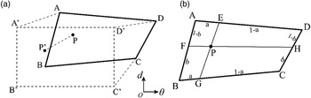
. Figure 3(a) shows four gathered initial poses,
 $A(\theta _{1},d_{1})\ B(\theta _{2},d_{2})\ C(\theta _{3},d_{3})\ D(\theta _{4},d_{4})$
, alongside their respective accurate poses
 $A'\big(\theta _{1}^{*},d_{1}^{*}\big)\ B'\big(\theta _{2}^{*},d_{2}^{*}\big)$
 $C'\big(\theta _{3}^{*},d_{3}^{*}\big)\ D'\big(\theta _{4}^{*},d_{4}^{*}\big)$
. The point
 $P$
symbolizes the pose
 $(\theta _{P},d_{P})$
acquired in real-time within a bad-plane-pose space. The corrected pose estimation
 $P'\big(\hat{\theta }_{P},\hat{d}_{P}\big)$
in the fine-plane-pose space can be determined as follows.
Mapping from the bad-plane-pose space to the fine-plane-pose space.

The corrected pose
 $P'\big(\hat{\theta }_{P},\hat{d}_{P}\big)$
and the initial pose
 $P(\theta _{P},d_{P})$
are interconnected by the intermediate variables, a and b. As depicted in Fig. 3(b), the points
 $E,G$
lie on segments
 $AD$
and
 $BC$
, respectively, dividing the segments
 $AD,BC$
with the same ratio a. Similarly, points
 $F,H$
are situated on the segments
 $BA$
and
 $CD$
, dividing these segments with the same ratio b. Segments
 $EG$
and
 $FH$
intersect at point
 $P$
. By performing the same operation within the quadrilateral
 $A'B'C'D'$
using the same ratios
 $a$
and
 $b$
, then the intersection point
 $P'$
signifies the corrected pose. The intermediate variables,
 $a$
and
 $b$
, can be obtained according to Eq. (7)
 \begin{equation} \left[\begin{array}{l@{\quad}l} \theta _{P} & d_{P} \end{array}\right]=\left[\begin{array}{l@{\quad}l} 1{-}a & a \end{array}\right]\left[\begin{array}{l@{\quad}c@{\quad}c@{\quad}c} b & 1-b & 0 & 0\\[4pt] 0 & 0 & 1-b & b \end{array}\right]\left[\begin{array}{l@{\quad}l} \theta _{1} & d_{1}\\[4pt] \theta _{2} & d_{2}\\[4pt] \theta _{3} & d_{3}\\[4pt] \theta _{4} & d_{4} \end{array}\right] \end{equation}
Subsequently, substituting the ratios a and b into the Eq. (7) yields Eq. (8).
 \begin{equation} \left[\begin{array}{l@{\quad}l} \hat{\theta }_{P} & \hat{d}_{P} \end{array}\right]=\left[\begin{array}{l@{\quad}l} 1{-}a & a \end{array}\right]\left[\begin{array}{l@{\quad}c@{\quad}c@{\quad}c} b & 1-b & 0 & 0\\[4pt] 0 & 0 & 1-b & b \end{array}\right]\left[\begin{array}{l@{\quad}l} \theta _{1}^{*} & d_{1}^{*}\\[4pt] \theta _{2}^{*} & d_{2}^{*}\\[4pt] \theta _{3}^{*} & d_{3}^{*}\\[4pt] \theta _{4}^{*} & d_{4}^{*} \end{array}\right] \end{equation}
The estimation of parameter pair with enhanced precision
 $\big(\hat{\theta }_{P},\hat{d}_{P}\big)$
is now ascertainable according to the Eqs. (7) and (8).
2.2.3. Plane pose space partitioning strategy
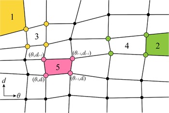
According to Eqs. (7) and (8), a minimum of four pairs of gathered poses are necessary to establish a local mapping, as illustrated in Fig. 3. The entire plane pose space comprises a number of local subspaces, as demonstrated in Fig. 4.
Entire pose space composing all mapped subspaces.

Figure 4 presents the abstract diagram of the bad-plane-pose space, where solid points represent the gathered initial pose data
 $\{(\theta _{i},d_{i})\}$
. By connecting neighbored points, a series of quadrilaterals is formed. The distortion of quadrilateral reflects the irregular initial pose identification error. Each quadrilateral corresponds to a single interpolation mapping function.
In Fig. 4, some subspaces are surrounded by less than four vertices and are denoted by regions marked with numbers 1 and 2, referred to as corner subspaces and edge subspaces, respectively. Excluding edge and corner subspaces, the remainder is designated as internal subspaces. The mapped functions of edge and corner subspaces can be constituted by their nearest internal subspaces, represented by subspaces marked with numbers 3 and 4 in Fig. 4.
Assuming the number of the gathered points matrix in the row is
 $n_{d}$
, and the number of the gathered points matrix in the column is
 $n_{\theta }$
. The entire
 $\theta -d$
space is divided into
 $(n_{\theta }+1)\times (n_{d}+1)$
grids. This including four corner subspaces,
 $2\times (n_{\theta }-1+n_{d}-1)$
edge subspaces, and
 $(n_{\theta }-1)\times (n_{d}-1)$
internal subspaces.
The method for identifying the corresponding subspace containing the to-be-corrected pose
 $P(\theta _{P},d_{P})$
is as follows. Convert the initial pose
 $P(\theta _{P},d_{P})$
into the homogeneous vector
 $\overline{\overline{{\boldsymbol{P}}}}=[\begin{array}{l@{\quad}l@{\quad}l} \theta _{p} & d_{p} & 1 \end{array}]^{T}$
. A judgment vector
 $\boldsymbol{J}\ \textbf{=}\ [\begin{array}{c@{\quad}c@{\quad}c@{\quad}c} J_{1} & J_{2} & J_{3} & J_{4} \end{array}]^{T}$
is defined by Eq. (9)
 \begin{equation} \boldsymbol{J}\ \textbf{=}\ \boldsymbol{Q}\overline{\overline{{\boldsymbol{P}}}} \end{equation}
where
 $\boldsymbol{Q}$
denotes a representive matrix for a quadrilateral, defined by Eq. (10).
 \begin{equation} \boldsymbol{Q}\ \textbf{=}\ \left[\begin{array}{l@{\quad}l@{\quad}l} a_{1} & b_{1} & c_{1}\\ a_{2} & b_{2} & c_{2}\\ a_{3} & b_{3} & c_{3}\\ a_{4} & b_{4} & c_{4} \end{array}\right] \end{equation}
Each row of the representive matrix
 $\boldsymbol{Q}$
in Eq. (10) signifies the coefficients of the line equation, representing one edge of the corresponding quadrilateral subspace in the pose coordinate system, as shown in Eq. (11).
 \begin{equation} a_{i}\theta +b_{i}d+c_{i}=0 \end{equation}
The initial pose point
 $P(\theta _{P},d_{P})$
is located within the quadrilateral subspace only when each element of the judgment vector
 $\boldsymbol{J}$
is positive. Upon determining the inclusion relationship between an initial pose
 $P(\theta _{P},d_{P})$
and its corresponding subspace is obtained, the corrected pose estimation
 $P'\big(\hat{\theta }_{P},\hat{d}_{P}\big)$
can be ascertained according to Eqs. (7) and (8).
2.3. Calibration platform and geometry analysis
A high-precision mechanical calibration platform is designed to gather high-quality mapping relations. The detected object sample and the camera device are affixed to the platform, which adjusts the relative pose between the camera and the plane. A to-be-corrected relative pose estimated by the vision system and an accurate relative pose supplied by the platform constitutes one pose mapping relation. The platform alters the relative poses to encompass the entire range of relative poses as extensively as possible.
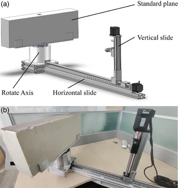
The calibration platform, as depicted in Fig. 5, is a three-degree-of-freedom platform with two translational degrees and one rotational degree. The rotation degree facilitates changing the detected plane’s inclination angle
 $\theta$
while the horizontal translational degree adjusts the distance
 $d$
between the detected plane and the camera. The supplementary vertical translation degree is employed solely for adjusting the camera’s height during initial platform assembly. High-precision encoders on the platform guarantee the accuracy of the acquired relative poses, with the camera situated on the vertical slide.
To attain heightened calibration precision, the target plane’s pose must be precisely known. Ideally, the sample had better be the actual detected object in the applied scenario. As shown in Fig. 5, a rectangular entity is positioned on the rotating table, with the center axis of the rotating table aligning with the block’s center axis. The entity’s front surface serves as the plane to-be-detected.
Each calibration initiation begins with an initialization process to ensure calibration accuracy. The platform propels the camera forward until its front surface aligns with the block’s surface. To verify the alignment of the camera with the block’s surface, a fragile piece of paper is placed between the two surfaces and the horizontal slider adjusted until the paper is neither too taut nor too slack.
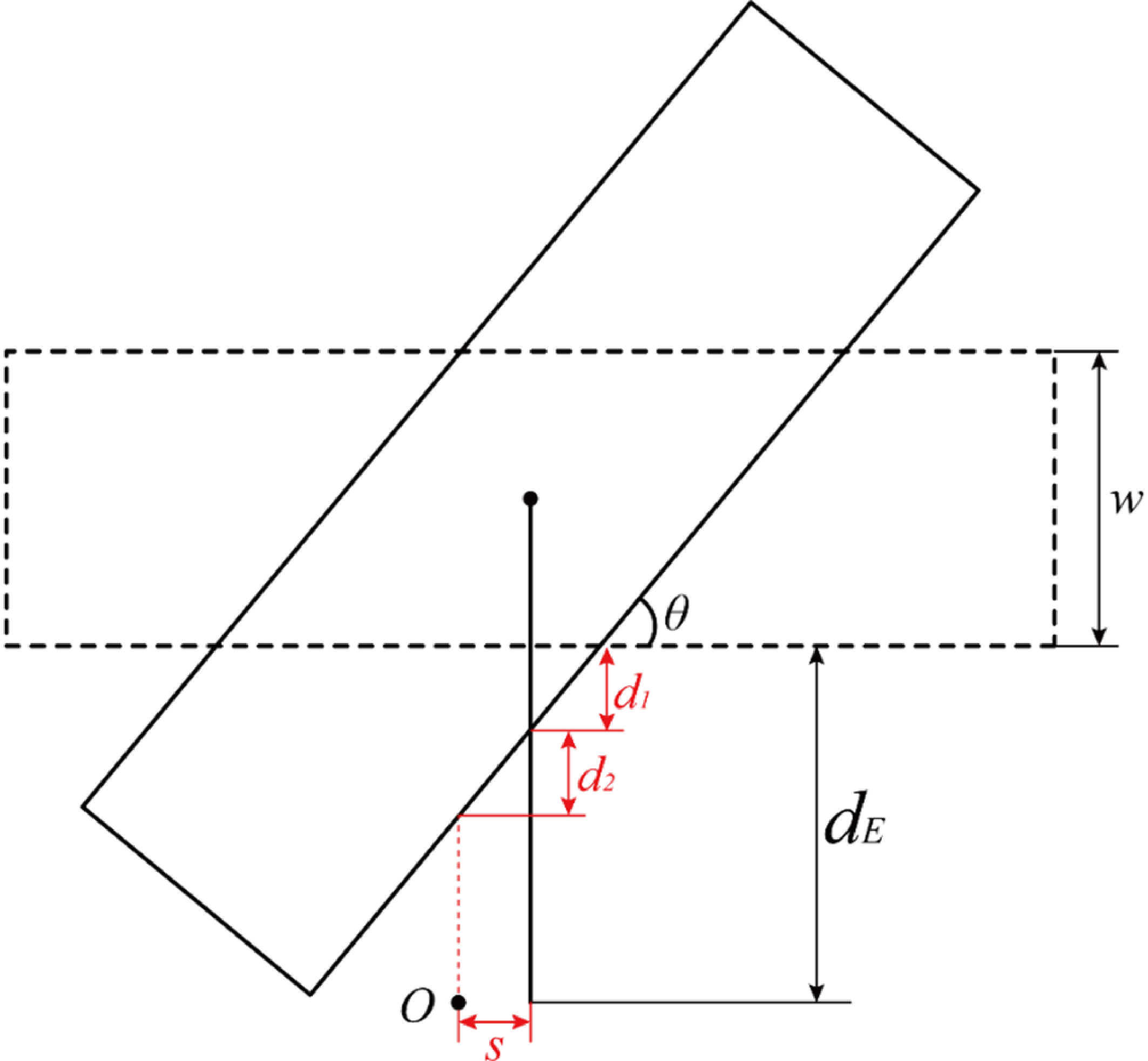
Nonetheless, the distance value derived from the horizontal slide cannot directly represent the distance between the camera and the target plane. Due to camera’s optical origin offset and the block’s thickness, the distance must be compensated. Figure 6 illustrates the geometry principle of the distance compensation from a top view.
Prototype of mechanical calibration platform.

Distance compensation of calibration platform.

The distance
 $d_{E}$
represents the value read directly from the horizontal slide. The offset
 $s$
signifies the lateral offset between the camera’s optical origin and the symmetrical plane. The distance
 $d_{1}$
and
 $d_{2}$
denote the compensation resulting from the block’s rotation and the lateral offset
 $s$
. The final modified distance can be expressed by Eq. (12).
 \begin{equation} d^{*}=d_{E}-d_{1}-d_{2}=d_{E}-\frac{w}{2}\left(\frac{1}{\cos \theta }-1\right)-s\tan \theta \end{equation}
The platform adjusts the relative poses according to the pre-defined distance list,
 $\{D_{j}|j=1,2,\ldots,\mathrm{n}_{D}\}$
, and angle list
 $\{\theta _{i}|i=1,2,\ldots,\mathrm{n}_{\theta }\}$
. Initially, the horizontal slide distance is set to
 $D_{1}$
, and the inclination angle is set to each value within the angles list sequentially. Subsequently, the distance is set to the remaining values in the distance list and the angle changes are repeated. Ultimately,
 $n_{D}\times n_{\theta }$
mapping relations are gathered from the calibration.
2.4. Preprocessing of raw point cloud data
Typically, a stereo camera can directly generate point clouds through methods based on binocular disparity or other principles. The random sample consensus (RANSAC) algorithm is an effective iterative method to identify planes from point clouds.
Prior to plane identification, pre-filtering points that may belong to the plane point cloud can eliminate numerous outlier points. If an excessive number of outliers exist beyond the target plane within the entire point cloud, they might influence the plane identification outcome. The region-of-interest (ROI) method is effective for filtering purposes.
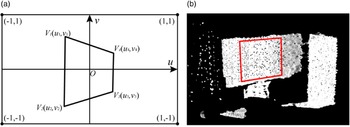
A planar image coordinate system (refer to Fig. 7) is established to represent the ROI filter employed on the calibration platform.
Planar coordinate system arrangement of camera view.

At a specific instant, there is one point,
 $P(x_{p},y_{p},z_{p})$
, lies within the camera coordinate system, and belongs to the real-time point cloud. Its corresponding point,
 $P(u_{P},v_{P})$
, in the defined image coordinate system is defined as
 \begin{equation} \left[\begin{array}{l} u_{P}\\[4pt] v_{P} \end{array}\right]=\left[\begin{array}{c@{\quad}c@{\quad}c} \dfrac{2}{\theta _{h}}\arctan & 0 & 0\\[12pt] 0 & \dfrac{2}{\theta _{v}}\arctan & 0 \end{array}\right]\left[\begin{array}{l} \dfrac{x_{P}}{z_{P}}\\[12pt] \dfrac{y_{P}}{z_{P}}\\[10pt] 1 \end{array}\right] \end{equation}
where
 $\theta _{h}$
denotes the horizontal field of view and
 $\theta _{v}$
signifies the vertical field of view. The operator arctan indicates the arc tangent operation. If a point is visible in the view field, the value ranges of its coordinates in the image coordinate system defined by Eq. (13) are
 $u_{P}\in [-1,1]$
and
 $v_{P}\in [-1,1]$
.
Suppose four known vertices of ROI in the camera coordinate system are
 $V_{1}(x_{1},y_{1},z_{1}), V_{2}(x_{2},y_{2},z_{2}), V_{3}(x_{3},y_{3},z_{3})$
, and
 $V_{4}(x_{4},y_{4},z_{4})$
.
 \begin{equation} \left[\begin{array}{c@{\quad}c@{\quad}c@{\quad}c} u_{1} & u_{2} & u_{3} & u_{4}\\[4pt] v_{1} & v_{2} & v_{3} & v_{4} \end{array}\right]=\left[\begin{array}{c@{\quad}c@{\quad}c} \dfrac{2}{\theta _{h}}\arctan & 0 & 0\\[10pt] 0 & \dfrac{2}{\theta _{v}}\arctan & 0 \end{array}\right]\left[\begin{array}{@{}c@{\quad}c@{\quad}c@{\quad}c@{}} \dfrac{x_{1}}{z_{1}} & \dfrac{x_{2}}{z_{2}} & \dfrac{x_{3}}{z_{3}} & \dfrac{x_{4}}{z_{4}}\\[14pt] \dfrac{y_{1}}{z_{1}} & \dfrac{x_{2}}{z_{2}} & \dfrac{x_{3}}{z_{3}} & \dfrac{x_{4}}{z_{4}}\\[13pt] 1 & 1 & 1 & 1 \end{array}\right] \end{equation}
In Eq. (14),
 $V_{1}(u_{1},v_{1}), V_{2}(u_{2},v_{2}), V_{3}(u_{3},v_{3}), V_{4}(u_{4},v_{4})$
are the corresponding coordinates in the defined image coordinate system.
Divide the quadrilateral ROI,
 $V_{1}V_{2}V_{3}V_{4}$
, into two triangles
 $\Delta V_{1}V_{2}V_{3}$
and
 $\Delta V_{1}V_{3}V_{4}$
. If a point situates within the ROI, it must lie in one of the triangles. The algorithm for determining whether point
 $P(x_{p},y_{p},z_{p})$
is located within the triangle
 $\Delta V_{1}V_{2}V_{3}$
is expressed in Eq. (15).
 \begin{equation} \left[\begin{array}{c@{\quad}c@{\quad}c} u_{1}\tan \!\left(\theta _{h}/2\right) & u_{2}\tan\!\left(\theta _{h}/2\right) & u_{3}\tan\! \left(\theta _{h}/2\right)\\[4pt] v_{1}\tan\! \left(\theta _{v}/2\right) & v_{2}\tan\!\left(\theta _{v}/2\right) & v_{3}\tan\!\left(\theta _{v}/2\right)\\[4pt] 1 & 1 & 1 \end{array}\right]\left[\begin{array}{l} J_{1}\\[4pt] J_{2}\\[4pt] J_{3} \end{array}\right]\ \textbf{=}\ \left[\begin{array}{l} x_{P}\\[4pt] y_{P}\\[4pt] z_{P} \end{array}\right] \end{equation}
where the vector
 $[\begin{array}{l@{\quad}l@{\quad}l} J_{1} & J_{2} & J_{3} \end{array}]^{T}$
represents the judgment vector. If each element of vector
 $[\begin{array}{l@{\quad}l@{\quad}l} J_{1} & J_{2} & J_{3} \end{array}]^{T}$
is positive, the point
 $P(x_{p},y_{p},z_{p})$
lies inside this triangle. If any element of the vector is negative, then the other triangle of the ROI,
 $\Delta V_{1}V_{3}V_{4}$
, should be examined.
For the proposed calibration platform, the ROI can be chosen as a rectangle affixed on the detected surface. Along with the changing of relative distance and inclination angle, real-time coordinates of vertices can be computed by using Eq. (16)
 \begin{equation} \boldsymbol{V}_{\mathrm{ROI}}^{*}=\boldsymbol{T}_{2}\boldsymbol{M}\boldsymbol{T}_{1}\boldsymbol{V}_{\mathrm{ROI}}^{0} \end{equation}
In Eq. (16),
 $\boldsymbol{V}_{\mathrm{ROI}}^{*}$
represents the real-time coordinates of ROI vertices, as defined by Eq. (17)
 \begin{equation} \boldsymbol{V}_{\mathrm{ROI}}^{*}=\left[\begin{array}{c@{\quad}c@{\quad}c@{\quad}c} V_{1}^{*} & V_{2}^{*} & V_{3}^{*} & V_{4}^{*} \end{array}\right] \end{equation}
In Eq. (16),
 $\boldsymbol{V}_{\mathrm{ROI}}^{0}$
signifies the coordinates of ROI vertices in the initial condition, as defined by Eq. (18).
 \begin{equation} \boldsymbol{V}_{\mathrm{ROI}}^{0}=\left[\begin{array}{c@{\quad}c@{\quad}c@{\quad}c} V_{1}^{0} & V_{2}^{0} & V_{3}^{0} & V_{4}^{0} \end{array}\right]=\left[\begin{array}{c@{\quad}c@{\quad}c@{\quad}c} -\dfrac{l_{1}}{2} & -\dfrac{l_{1}}{2} & \dfrac{l_{1}}{2} & \dfrac{l_{1}}{2}\\[9pt] \dfrac{l_{2}}{2} & -\dfrac{l_{2}}{2} & -\dfrac{l_{2}}{2} & \dfrac{l_{2}}{2}\\[9pt] c_{0} & c_{0} & c_{0} & c_{0}\\[4pt] 1 & 1 & 1 & 1 \end{array}\right] \end{equation}
where
 $l_{1}$
denotes the length of the rectangle and
 $l_{2}$
represents the height of the rectangle. The initial state of the platform is defined as the status
 $\theta =0,d=0$
. The symbol
 $c_{0}$
denotes the displacement between the camera’s optical origin and the front surface.
In Eq. (16), the matrix
 $\boldsymbol{T}_{1}$
represents a transformation matrix, as shown in Eq. (19)
 \begin{equation} \boldsymbol{T}_{1}=\left[\begin{array}{c@{\quad}c@{\quad}c@{\quad}c} 1 & 0 & 0 & 0\\[4pt] 0 & 1 & 0 & 0\\[4pt] 0 & 0 & 1 & -\dfrac{w}{2}-c_{0}\\[9pt] 0 & 0 & 0 & 1 \end{array}\right] \end{equation}
where w denotes the thickness of the sample entity.
In Eq. (16), the matrix
 $\boldsymbol{M}$
represents a transformation matrix, as depicted in Eq. (20)
 \begin{equation} \boldsymbol{M}=\left[\begin{array}{c@{\quad}c@{\quad}c@{\quad}c} \cos \theta & 0 & -\sin \theta & 0\\[4pt] 0 & 1 & 0 & 0\\[4pt] \sin \theta & 0 & \cos \theta & 0\\[4pt] 0 & 0 & 0 & 1 \end{array}\right] \end{equation}
where
 $\theta$
denotes the relative inclination angle.
In Eq. (16), the matrix
 $\boldsymbol{T}_{2}$
represents a transformation matrix, as shown in Eq. (21)
 \begin{equation} \boldsymbol{T}_{2}=\left[\begin{array}{c@{\quad}c@{\quad}c@{\quad}c} 1 & 0 & 0 & 0\\[4pt] 0 & 1 & 0 & 0\\[4pt] 0 & 0 & 1 & d^{*}+\dfrac{w}{2}+c_{0}\\[9pt] 0 & 0 & 0 & 1 \end{array}\right] \end{equation}
where
 $d^{*}$
denotes the modified distance defined by Eq. (12).
3. Experimental validation
3.1. Devices overview
Intel RealSenseTM D435i (abbreviated as D435i throughout this article) is a compact, low-cost, consumer-grade, binocular stereo camera. RealSense series camera are popular in various applications. Keselman et al. [Reference Keselman, Woodfill, Grunnet-Jepsen and Bhowmik39] discussed the performances and limitations of RealSense cameras. Zhu et al. [Reference Zhu, Zhang, Wang and Cheng6] employed the D435i for safety monitoring of solitary individuals. Huynh et al. [Reference Huynh and Kuo40] utilized D435i for estimating robot poses. Rong et al. [Reference Rong, Wang, Yang and Huang41] used it for recognizing oyster mushrooms in auto-harvesting.
Most D435i applications are qualitative, such as morphology detection or color feature recognition. The official document for the D435i states a relative error of 2% of the distance. Among the ten recently published papers that mentioned D435i in their abstracts [Reference Neupane, Koirala, Wang and Walsh29–Reference Bung, Crookston and Valero32, Reference Rong, Wang, Yang and Huang41–Reference Oščádal46], only four utilize the camera’s measurement function. When measuring the length of the grape clusters [Reference Peng, Zhao and Liu30], the error ranges from around –20 to 20 mm. Neupane et al. [Reference Neupane, Koirala, Wang and Walsh29] conducted an experiment measuring ceramics, PTFE, and fruits, with measurement residuals for the D435i ranging from 5 to 240 mm with measurement distance varying from 400 to 4000 mm. Measurements on the sewers [Reference Bahnsen, Johansen, Philipsen, Henriksen, Nasrollahi and Moeslund31] show errors from around 40 to 130 mm, while fluid surface measurements [Reference Bung, Crookston and Valero32] reveal errors from approximately 10 to 60 mm. These precision values are appraised reading from the figure reported in the cited papers. Some cameras mentioned in these papers are actually D435 model, which differs from D435i only in the presence of an inertial measurement unit.
The experiment in this section utilizes D435i to demonstrate the extent to which precision can be increased using the existing method. Improved precision enables the adoption of the D435i in quantitative and high-precision-required scenarios.
The geometric parameters of D435i are as follows: the lateral offset of optical origin to the symmetrical plane is
 $s=17.5\text{ mm}$
; the longitudinal offset of optical origin to the camera surface is
 $c_{0}=4.2\text{ mm}$
; the horizontal field of view is
 $\theta _{h}=86^{\circ }$
; the vertical field of view is
 $\theta _{v}=57^{\circ }$
.
The encoders in the slides and the rotation joint of the calibration platform ensure accuracy during the fine pose data gathering process. The linear translation stage employs a closed-loop stepper system. The slide encoder’s resolution is 5
 $\unicode{x03BC}$
m/pulse. And the absolute translation error is, at most, 0.03 mm according to the slide’s official statement.
The resolution for the rotation motor’s encoder is 19 bits, corresponding to 524,288 counts per revolution or 0.00069° per count. Typically, the position error is larger than the numerical resolution. According to the official statement, the motor’s maximum absolute position error is 0.05°.
3.2. Calibration data acquisition
A RANSAC-based method implemented in PCL Library (PCL-RANSAC) [Reference Rusu and Cousins28] serves as the experimented plane identification method to be calibrated. The PCL Library is an open project for point cloud processing and is widely used in research [Reference Fotsing, Menadjou and Bobda26, Reference Miknis, Davies, Plassmann and Ware47, Reference Holz, Ichim, Tombari, Rusu and Behnke48]. In the experiments, PCL-RANSAC threshold is set to 0.005 m.
A list of standard distances and angles in calibration can be found in Appendix A. At each set of distance and inclination angle values, 20 sets of point cloud are captured. As random error cannot be ignored in single measurement, averaging 20 measurements to reduce random errors.
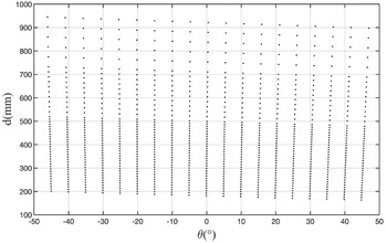
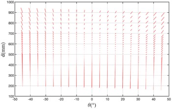
Following the previously introduced calibration processes, the calibration data of initial poses in bad-plane-pose space is shown in Fig. 8.
Calibration data of initial poses in bad-plane-pose space.

In Fig. 8, each solid point represents an initially detected pose obtained by the stereo system, with the distribution of the points appearing distorted.
To display the difference between initial pose points and the accurate ones, segments connecting each initial pose point to its corresponding accurate pose point are shown in Fig. 9.
Mapping relations from initial poses to corrected poses.

Each segment in Fig. 9 represents a mapping relation from the initial pose to the accurate pose. Then, using the interpolation method represented in Section 2, any online detected initial pose can be corrected to a more precise one.
3.3. Validation on correcting the pose identified by PCL-RANSAC
Comparisons are made between the poses identified by PCL-RANSAC and the results after correcting by using the proposed method.
First, a comparison of distance identification is made. The inclination of the plane angle is fixed at
 $\theta =0$
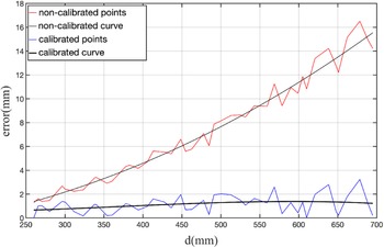
in this comparison experiment. Tested distance values are randomly chosen every 10 mm from 260 to 700 mm.
Figure 10 displays the comparison of the identified distances before and after the calibration mapping. The red polylines represent the initial data from PCL-RANSAC. Random errors cause fluctuation around an approximate linear increasing trend. The identification error increases with the detected distance. After calibrating the initial distance, errors are reduced to a much lower level, represented by the blue polyline shown in Fig. 10.
Comparison before and after calibration with varied plane distances.

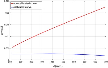
Figure 11 displays the relationship between the ratio of error and distance, illustrating the correlation between the error and distance. The results show that the ratio increases along with the distance increasing before calibration. However, after calibration, the ratio does not exhibit significant changes.
The relationship between the ratio of error to observing distance and observing distance.

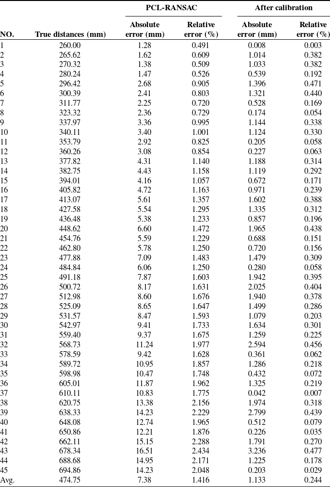
Data points with errors ten percent larger than the observed distance are considered outliers and ignored. The results of the distance correction experiment are shown in Table B1, Appendix B.
In addition to distance experiments, a comparison on both distance and inclination angle identification is conducted. Distances are chosen randomly every 10 mm, from 200 to 800 mm. The inclination angles are chosen randomly every 10° from –45° to 45°.
Figure 12 shows the comparison between calibrated and non-calibrated poses in the
 $\theta -d$
coordinate system.
Comparison before and after calibration with varied distances and angles.

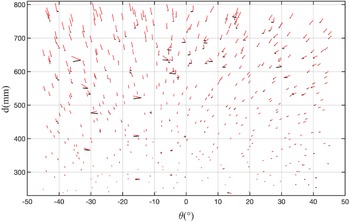
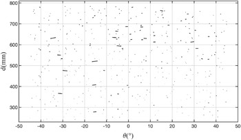
In Fig. 12, red segments connect the accurate pose points to the non-calibrated pose points, while black segments connect the accurate pose points to the calibrated ones. For clarity, Fig. 13 illustrates the calibrated segments only.
Results of distance and angle correction experiment.

Lines connected accurate pose points and calibrated pose points.

From Figs. 12 and 13, the comparison clearly shows a significant reduction in errors. However, in Fig. 13, some segments are still noticeable compared to others. These segments, which are nearly parallel to the
 $\theta$
axis, indicate that the angle errors of these points do not achieve good results. Nonetheless, compared to Fig. 12, the original data for these samples are already unformatted compared to the other data. These unusual error samples are likely caused by random noises and fluctuations in the point cloud. Most samples are calibrated to a low-error value, even including a few abnormal samples.
The results of the distance and angle correction experiment are shown in Table I. The mean absolute error of distances, the mean relative error of distances, and the mean absolute error of angle are listed. Before calculating the averages, absolute operations are performed on each original value.
According to the results in Table I, this calibration significantly improves the precision of distance and angle identification over PCL-RANSAC.
4. Application to construction robotics
A construction robot discussed herein, a mobile manipulator, comprises a 6-degree-of-freedom robotic arm, an elevation mechanism, and a wheeled chassis, endowing it with redundant mobility capabilities suitable for construction tasks. The robotic arm is responsible for carrying and positioning bricks, while the wheeled chassis ensures ample workspace for the construction robot.
The aforementioned calibration method for plane parameter identification is utilized during brick wall construction processes. The primary objective is to accurately position each brick.
Assuming a brick wall comprises
 $n_{1}$
layers and
 $n_{2}$
bricks per layer. The pose information for a brick is denoted by vector
 $\boldsymbol{b}_{ij}=[x_{ij},y_{ij},z_{ij},a_{ij},b_{ij},c_{ij}]^{T}$
. The first three components represent the spatial coordinates of the brick’s center, and the remaining three signify the front surface’s normal vector.
Matrix
 $\boldsymbol{B}^{\mathrm{*}}$
, the target matrix, encapsulates the construction task and contains the desired pose for each brick, as articulated in Eq. (22).
 \begin{equation} \boldsymbol{B}^{\mathrm{*}}=\left[\begin{array}{c@{\quad}c@{\quad}c} \boldsymbol{b}_{11}^{\mathrm{*}} & \ldots & \boldsymbol{b}_{1n_{2}}^{\mathrm{*}}\\ \ldots & \ldots & \ldots \\ \boldsymbol{b}_{n_{1}1}^{\mathrm{*}} & \ldots & \boldsymbol{b}_{n_{1}n_{2}}^{\mathrm{*}} \end{array}\right] \end{equation}
The construction of an autonomous robot involves iteratively retrieving bricks from storage and accurately positioning them in the designated area until all bricks have been placed.
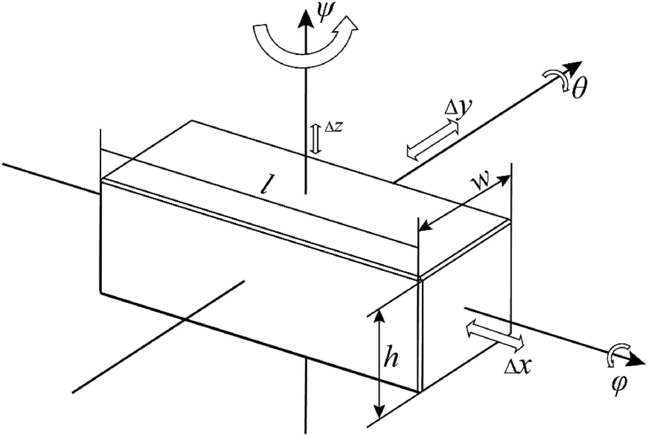
Accurate pose detections are performed for bricks on the wall, as illustrated in Fig. 14. All bricks share uniform dimensions, l, d, and h correspond to length, width, and the height. Brick’s pose is expressed through yaw(
 $\psi$
), pitch(
 $\theta$
), and roll(
 $\phi$
). Given that the brick’s bottom surface rests atop the foundation wall, it remains approximately parallel to the ground. Consequently, yaw is emphasized during pose detection, while pitch and roll are comparatively negligible, as they are constrained by the alignment of the bottom and upper surfaces. Similarly, the displacements
 $\bigtriangleup x$
and
 $\bigtriangleup y$
are prioritized over
 $\bigtriangleup z$
, as demonstrated in Fig. 14.
Brick’s position and orientation.

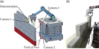
A multi-camera stereo system is then established to reduce constructing error. Three cameras, positioned on the robot as shown in Fig. 15, ensure the placing precision. Camera 1, mounted on the robot’s gripper, detects the side planes of existing bricks, while the other two cameras, situated at the robot’s front, monitor the caught brick’s outer surface and brick wall’s outer surface. The robot identifies the foundation wall’s pose while placing each brick, thus ensuring precise placement.
Construct the brick wall with a mobile manipulator. (a) overall view of the robot system. (b) prototype experiment.

The proposed calibration method is applied to automate brick wall construction using the robot, achieving a flatness performance below 4 mm.
5. Results and discussion
The calibration process may be perceived as a rectification procedure for any plane poses identification algorithm. Subsequent to plane pose correction, precision is enhanced relative to the initial plane pose. Validations are conducted employing a widely used plane pose identification algorithm, PCL-RANSAC. As indicated by the experimental outcomes in Table I, the mean absolute distance error diminishes from 7.350 to 0.9091 mm. The mean relative error of distance declines from 1.292 to 0.2378%. The mean absolute angle error decreases from 0.4299° to 0.2530°. The angle identification error has no notable correlation to the true pose angle. Thus, the mean relative angle error is not enumerated in Table I.
The experimental results validate that the proposed calibration method and mechanical platform can augment the precision. Relative to the method reported in ref. [Reference Darwish, Li, Tang, Wu and Chen35], the proposed calibration method demonstrates superior performance at short detected distances. The relative error reported in ref. [Reference Darwish, Li, Tang, Wu and Chen35] is 0.867% at 0.8 m, –1.346% at 0.802 m, –0.520% at 0.947 m, and 0.298% at 1.110 m. Moreover, the relative error reported in ref. [Reference Li, Li, Darwish, Tang, Hu and Chen36] is 0.49% at 1.23 m. Conversely, our results reveal a mean relative distance error of 0.2378% within 1 m.
No specific camera distortion model is required in our calibration method, unlike the method proposed in refs. [Reference Darwish, Li, Tang, Wu and Chen35] and [Reference Li, Li, Darwish, Tang, Hu and Chen36]. The bilinear interpolation method can fit any camera distortion model, provided the system error of plane pose identification remains continuous at varying distances and angles.
Additionally, the mechanical platform shows crucial for enhanced calibration. The interpolation-based method demands extensive data collection to better fit the error functions. The mechanical platform can swiftly move and accurately position itself, facilitating calibration completion in a minimal timeframe.
As depicted in Fig. 10, a biased residual of approximately 2 mm persists after calibration. This may be attributable to suboptimal initial calibration data collection. As demonstrated in Fig. 9, the original calibration data points are unevenly distributed. Moreover, despite the mechanism resolution sufficiency for precise pose calculation, installation errors of components and the detected plane sample’s nonideality may engender errors.
6. Conclusions
This article presents a calibration method that does not rely on particular camera distortion models for plane identification. A high-precision, three-degree-of-freedom mechanical calibration platform is devised to perform high-precision calibration data gathering tasks. The platform gathers mapping relations between low-precision plane poses derived from the stereo system and accurate plane poses obtained from the platform. By employing the interpolation method, any real-time acquired plane pose can be rectified to a more precise one by utilizing pre-gathered mapping relations. Experimental comparisons validate the plane pose correction’s efficacy on PCL-RANSAC. The mean absolute distance error reduces from 7.350 to 0.9091 mm, the mean relative distance error diminishes from 1.292 to 0.2378%, and the mean absolute error of angle reduces from 0.4299° to 0.2530°. This calibration method can be applied to any plane parameters identification algorithm, as long as the initially identified pose exhibits a biased error. Simultaneously, this method can be employed in other plane detection scenarios except for the plane pose detection of brick surfaces.
Author contributions
Junjie Ji conceived and designed the study. Junjie Ji conducted analysis and data gathering. Junjie Ji wrote the article. Jing-Shan Zhao revised the manuscript and provided supervision. All authors read and approved the final manuscript.
Financial support
This work was supported in part by 2020GQI1003, Guoqiang Research Institute of Tsinghua University.
Competing interests
The authors declare none.
Ethical standards
Not applicable.
Appendix A
During the calibration data collection process by a mechanical platform, distance values are designated at 200 mm, 210 mm, 220 mm, 230 mm, 240 mm, 250 mm, 260 mm, 270 mm, 280 mm, 290 mm, 300mm, 310 mm, 320 mm, 330 mm, 340 mm, 350 mm, 360 mm, 370 mm, 380 mm, 390 mm, 400mm, 410 mm, 420 mm, 430 mm, 440 mm, 450 mm, 460 mm, 470 mm, 480 mm, 490 mm, 500 mm, 520mm, 540 mm, 560 mm, 580 mm, 600 mm, 620 mm, 640 mm, 660 mm, 680 mm, 700 mm, 740 mm, 780mm, 820 mm, 860 mm, and 900 mm. Inclination angle values are designated at –45°, –40°, –35°, –30°, –25°, –20°, –15°, –10°, –5°, 0°, 5°, 10°, 15°, 20°, 25°, 30°, 35°, 40°, and 45°.
Appendix B
Table B1 enumerates the results of the distance correction experiment.
Results of distance correction experiment.