I. INTRODUCTION
Carbon nanotubes (CNTs) are of great interest for multifunctional reinforcement of polymer composites, as well as many other applications, including several already in the market,Reference De Volder, Tawfick, Baughman and Hart1 due to their extraordinary properties such as high Young’s modulus, good flexibility, and high electrical and thermal conductivities. A variety of reviews summarize the extent of the basic work, the advances, and challenges, as well as commercial applications of polymer nanotube composites.Reference Schaefer and Justice2,Reference Spitalsky, Tasis, Papagelis and Galiotis3
Polyaniline (PAni) composites are of particular interest since this conducting polymer shows good processability, outstanding environmental stability, and its electrical conductivity can be modified by doping via acid–base reactions and electrochemistry, which make a variety of applications possible.Reference Salaneck, Lundstrom, Huang and MacDiarmid4,Reference Zarras, Irvin and Mark5
Both single-walled CNTs and multi-walled CNTs (MWCNTs) can improve the mechanical properties as well as enhance further the high electrical conductivity of PAni.Reference Maser, Benito, Callejas, Seeger, Martínez, Schreiber, Muszinsky, Chauvet, Osváth, Kóos and Biró6–Reference Mottaghitalab, Spinks and Wallace8 For example, CNTs have been used to improve the electrical properties of battery electrodes,Reference Wang, Mottaghitalab, Too, Spinks and Wallace9 the electrochemical performance of supercapacitors,Reference Sivakkumar, Kim, Choi, MacFarlane, Forsyth and Kim10,Reference Zhang, Kong, Wang, Luo and Kang11 and the mechanical and electrical properties of actuators.Reference Mottaghitalab, Spinks and Wallace12
Electrochemical oxidative polymerization of aniline is a classical route for PAni but is limited to film deposition.Reference Zarras, Irvin and Mark5 For larger scale synthesis, a chemical polymerization route, with the monomer oxidized in solution, typically using ammonium persulfate (APS), can be used. This route can produce PAni nanostructures under specific conditions.Reference Huang and Kaner13–Reference Stejskal, Sapurina, Trchová and Konyushenko15 In this report, we focus on a less studied route which does not require organic solvents nor strong oxidizers to synthesize PAni: mechanochemistry.
Mechanochemical techniques have the advantage of reducing energy requirements and minimizing waste for several organic reactionsReference Nasir Baig and Varma16 but have not been extensively studied for polymerizations nor for in situ synthesis of composites.
Ball milling has been previously used for preparation of CNTs–polymeric composites; however, in most cases, the technique has been used only as a dispersion tool, where CNT bundles are separated into individual nanotubes by ball milling means and mixed with an already prepared polymeric matrix, such as polystyrene,Reference Suemori, Watanabe and Hoshino17 or poplypropylene.Reference Enqvist, Ramanenka, Marques, Gracio and Emami18 In fewer cases, the ball mill is used to disperse CNTs in a prepolymer component, such as a polyether polyol paste, which is used later to prepare a CNT–polyurethane composite.Reference Zhai, Li, Fei and Xia19 Other carbon nanomaterials have also been mixed with presynthesized polymers such as graphene oxideReference Liu, Wang, Li, Jiang, Wang, Shao, Zhang and Cui20 or graphene.Reference Ambrosio-Martín, Gorrasi, Lopez-Rubio, Fabra, Mas, López-Manchado and Lagaron21 Ball milling has also been applied for other types of nanocomposites, such as metals or metal oxide nanoparticles in polymer matrices.Reference Delogu, Gorrasi and Sorrentino22
Polymerization during ball milling is a less common procedure. Huang et al. reported a mechanochemical route to branched pure and conductive PAni-nanofibers by ball milling anilinium salt and an oxidant under ambient conditions, without any solvent.Reference Huang, Moore, Acquaye and Kaner23 Others have studied a similar mechanochemical synthesis of PAni or its derivatives by means of manual grinding of aniline salts and oxidant agents in a mortar.Reference Abdiryim, Xiao-Gang and Jamal24–Reference Abdiryim, Jamal and Nurulla26 Du et al.Reference Du, Zhou, Wang and Mai27 synthesized branched PAni-nanofibers by hand-grinding ferric chloride (FeCl3·6H2O) and aniline hydrochloride (C6H7N·HCl) obtaining a maximum synthesis yield of ∼8% comparable to that of the interfacial method (6–10%).Reference Huang, Moore, Acquaye and Kaner23 To the best of our knowledge, there has only been one report of a mechanochemical method for the PAni–MWCNT composite by manual grinding of MWCNT impregnated with aniline monomer, p-toluenesulfonic acid and APS in a mortar.Reference Ubul, Jamal, Rahman, Awut, Nurulla and Abdiryim28
More common methods for CNT–PAni composites are in situ polymerization, dispersing CNTs in the acidic mediumReference Cochet, Maser, Benito, Callejas, Martinez, Benoit, Schreiber and Chauvet29; or mixing PAni (which is positively charged) and CNTs (oxidized to provide negative carboxylates), using electrostatic interactions to drive mixingReference Yan, Han, Yang and Tay30; as well as dispersing CNTs in PAni solutions using N-methyl-2-pyrrolidone (NMP) or N,N′-dimethyl propylene urea.Reference Mottaghitalab, Spinks and Wallace12 These processes tend to depend on slow reactions and typically involve the use of organic solvents, as well as strong acids and oxidants.
In this work, we report for the first time a method whereby ball milling a mixture of MWCNTs with aniline hydrochloride and iron chloride produces a hybrid material, with nanotubes well mixed in between PAni nanoparticles forming a nanocomposite, in a single step, and with little mechanical damage to the CNT. Neither organic solvents nor acids were used, as the doping is provided by the anilinium hydrochloride itself, and the oxidizing agent is a mild one. A response surface (RS) experimental designReference Montgomery31 was used to select the optimum conditions for yield and dispersion as a function of several factors. We found this method to be useful to produce PAni composites in one step with both regular MWCNT and with nitrogen-doped nanotubes (CNx–MWCNT). We decided to use CNx, in addition to undoped nanotubes since they are more reactive and dispersible in polar solvents, including aqueous solutions, due to doping and have been reported to have better interactions with matrices in polymer composites.Reference Fragneaud, Masenelli-Varlot, Gonzalez-Montiel, Terrones and Cavaillé32
II. MATERIALS AND METHODS
In all experiments, we used aniline hydrochloride (hereafter: Ani·HCl; [C6H7N·HCl] 97%, Sigma Aldrich, St. Louis, Missouri), and iron(III) chloride hexahydrate (FeCl3·6H2O, ACS grade, Fermont, Monterrey, México) as the oxidant, hexahydrate was always used but is referred to as “FeCl3” in the text for convenience. We used distilled water in all experiments. Ethanol (95%, CTR Scientific, Monterrey, México) was used to remove unreacted Ani·HCl and by-products after recovering the nanocomposites by filtration.
We produced MWCNTs and CNx by Chemical Vapor Deposition (CVD),Reference Kamalakaran, Terrones, Seeger, Kohler-Redlich, Rühle, Kim, Hayashi and Endo33,Reference Terrones, Kamalakaran, Seeger and Rühle34 using 2.5 wt% ferrocene in toluene (benzylamine in the case of CNx) in an ultrasonic nebulizer. The aerosol was carried by an argon flow of 2.5 L/min, into a quartz tube furnace at a constant temperature of 800 °C, for 30 min. CNTs were purified by dispersing them with a pulsed probe sonicator in water under reflux, followed by reflux in HCl (6 M) and filtration, a method we have used in the pastReference Espinosa-González, Rodríguez-Macías, Cano-Márquez, Kaur, Shofner and Vega-Cantú35 to successfully remove amorphous carbon, facilitating dispersion of the nanotubes.
A. General synthesis procedure
Milling was performed in an orbital ball mill Mixer Mill 8000D (SPEX SamplePrep, Metuchen, New Jersey) in 62-mL steel vials (two experiments were run at the same time), using three 12.4-mm diameter and three 5-mm diameter steel balls. Ani·HCl, FeCl3, CNTs, and distilled water were added to the vial in the amounts specified in Sec. III. After the ball milling process, a wet paste was removed from the vial and any residue was rinsed off the vial and balls with distilled water. The products were collected over 0.45 μm pore size nylon microfiltration membranes under vacuum and washed with ∼120 mL of ethanol, followed by ∼100 mL of distilled water and finally ∼40 mL of ethanol to remove any unreacted substances. The hybrid materials were then dried in an oven at 100 °C before weighing. The polymer yield was determined as a percentage of the weight of the nanocomposite (minus the weight of CNT) with respect to the amount of monomer used.
B. Screening experiments
To test whether sonication helped the dispersion of CNT, we sonicated 40.4 mg CNx in 7 mL water (since the nitrogen doped nanotubes are more dispersible than the undoped MWCNT) for 60, 30, or 0 min, followed by milling for 20 min, with 8.34 g FeCl3 and 2.02 g aniline (molar ratio 2:1 FeCl3:Ani·HCl). We then used a ½2k factorial design to screen the effect on polymer yield and nanotube dispersion using 2 levels of k = 3 initial variables: water volume (2 and 12 mL), molar ratio of oxidant to aniline (1:1 with 4.17 g FeCl3; 2:1 using 8.34 g), and milling time (20 and 60 min).
C. Response surface experimental design
We selected a Box–Behnken RS experimental design to evaluate the effect of three factors in PAni yield and nanocomposite conductivity. We used water volume levels of 2, 7, and 12 mL, and three levels (0, 20.2, and 40.4 mg) of two types of nanotubes (MWCNT and CNx). In this design, we kept constant the FeCl3:Ani ratio at 2:1 (8.34 g FeCl3·6H20, 2.02 g Ani·HCl) and milling time at 20 min.
D. Characterization
The morphology and dispersion of the CNT in the nanocomposites were observed by scanning electron microscopy (SEM) on a FEI-XL-30-SFEG (FEI Company, Hillsboro, Oregon) with a scanning transmission electron microscopy (STEM) accessory, and also in the regular SEM mode. For STEM, drops of dilute hybrid material suspension were deposited over lacey carbon grids.
X-ray diffractograms were acquired with a Bruker D8 ADVANCE (Bruker, Karlsruhe, Germany; Cu anode, λ = 1.5406 Å, operating at 35 kV). Raman spectra were acquired with a Renishaw InVia microRaman using a HeNe laser (Renishaw, West Dundee, Illinois; 633 nm).
The electrical conductivity was measured with a four-point probe (Jandel CYL-1.0-100-TC-100-1M, Jandel Engineering, Linsdale, United Kingdom) using a Keithley 2400 SourceMeter (Keithley Instruments, Cleveland, Ohio). The nanocomposites were formed into square films (5 mm side, ∼0.5 mm thickness) by cutting the deposited film obtained from microfiltration, each sample measurement was repeated five times.
III. RESULTS AND DISCUSSION
A. Screening experiments
We first used water as a processing aid to disperse the CNT by sonication before adding them to the ball mill vessel, with the intention of enhancing dispersion in the final product, and found that sonication had no effect on nanotube dispersion in the final product, thus we omitted this step in other experiments since the vigorous and energetic mixing that occurs during ball milling was enough to disperse the nanotubes in the polymer.
Comparison experiments, made by performing ball milling without water, showed much lower polymer yields (only 0.3%), while using water the yields were ∼1.75%. This indicated that the addition of water can be an important factor.
The effect of water does not appear to have been studied by other authors. Du et al.Reference Du, Zhou, Wang and Mai27 called their synthesis a “dry” method but they use as oxidant FeCl3, a salt known to be deliquescentReference O’Neil36; with the reaction open to the atmosphere, moisture would have easily been absorbed from the air, and they indeed report that at the end of the hand grinding, they have a wet paste.
We made a series of screening experiments that showed that the addition of water was indeed a critical factor to increase the polymer yield. These are discussed in detail in the Supplementary Material, with the experimental design and the polymer yields shown in Table S1. Regression analysis showed that increasing water volume in the reaction (V W) increases polymer yield, while the oxidant to monomer ratio (Ox) of 1:1 or 2:1 gives about the same yield. We kept the larger ratio to ensure that there was a 2× stoichiometric excess of the oxidant (FeCl3). Intriguingly, the regression analysis suggested that longer milling times (60 min, instead of 20) could decrease the polymer yield. We think this could be explained due to ball milling induced polymer bond breaking.Reference Sohma37,Reference Caruso, Davis, Shen, Odom, Sottos, White and Moore38
These experiments confirmed our supposition that addition of water is an important factor when FeCl3 is used as the oxidant in PAni synthesis by milling. In solid-state synthesis, the diffusion of solid precursors can limit the yieldReference Huang, Moore, Acquaye and Kaner23; the addition of water in our experiments can be a physical effect that reduces this limitation, by dissolving both anilinium chloride and iron chloride; we also consider likely that water facilitates the reduction of iron as solvated Fe+3 ions. We kept V W as a variable in subsequent experiments to study further the effect of water in the reaction.
B. Optimization experiments
In this set of experiments, we used two types of nanotubes to evaluate if the nitrogen doping of CNx resulted in different interactions with PAni, due to their higher reactivity. Nitrogen doping also introduces electron states that make the rolled graphene sheets forming the tube metallic conductors, despite their chirality,Reference Ewels and Glerup39,Reference Ayala, Arenal, Rümmeli, Rubio and Pichler40 thus CNx could be expected to be more conductive than undoped MWCNTs (a mixture of metallic and semiconducting tubes), which could result in differences in electrical conductivity of the nanocomposites.
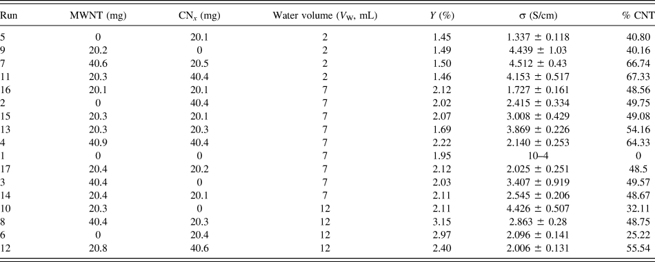
We selected a surface response optimization design with three levels (Low, Medium, and High) for three variables: weight of MWCNT, weight of CNx, and volume of water. The amounts of both types of CNT used, and the values for water volume, are shown in Table I, together with the yield and conductivity results, ordered by ascending water volume levels.
Results of the RS experiment for yield (Y) and conductivity (σ) of PAni–CNT composites. The experiments were run in random order; the run number is the nominal order in the experimental design, shown for reference only.

Table I makes it evident that V W is a critical variable for PAni yield (Y), which varied from 1.45 to 3.15% (average 2.05 ± 0.48%). The regression model by analysis of variance for this design of experiments is explained in detail in the Supplementary Material. It shows that water volume is the most important factor on polymer yield and that the presence of nanotubes has a very small effect, as expected, since the CNT should not affect this polymerization reaction. Interactions between variables were not significant regarding polymer yield.
Electrical conductivity (σ) varied from ∼10−4 (pure PAni) to 4.51 S/cm, with a mean value of 2.76 ± 1.25% S/cm. This value is comparable to the conductivity of CNT–PAni composites produced by other methods, as summarized in a review by Spitalsky et al.Reference Spitalsky, Tasis, Papagelis and Galiotis3 The regression model and its analysis are shown in the Supplementary Material, which also includes a plot of conductivity versus nanotube concentration (Fig. S1). Both types of CNT increase the conductivity significantly and to similar orders of magnitude. CNT contents above 25% increase conductivity only slightly further, indicating that the CNT concentrations are well above the percolation threshold. There is no clear correlation between percentage of nanotubes and conductivity, as shown in Fig. S1. The dispersion in conductivity data could be in part because nitrogen-doped and undoped MWCNTs contribute differently to the conductivity: theoretically, CNx have a greater conductivity than undoped MWCNT, but in practice, CNx have structural defects that disperse electrons, making their actual conductivity lower than the theoretical values. It should also be noted that when CNT lengths are shortened, conductivity decreases.Reference Czerw, Terrones, Charlier, Blase, Foley, Kamalakaran, Grobert, Terrones, Tekleab, Ajayan, Blau, Rühle and Carroll41 In addition to CNx defects, and the experimental error intrinsic in the measurements of conductivity, another source of scatter in these results could be experimental error in measuring the percentages of CNT (e.g., due to losses of the sample during transfers).
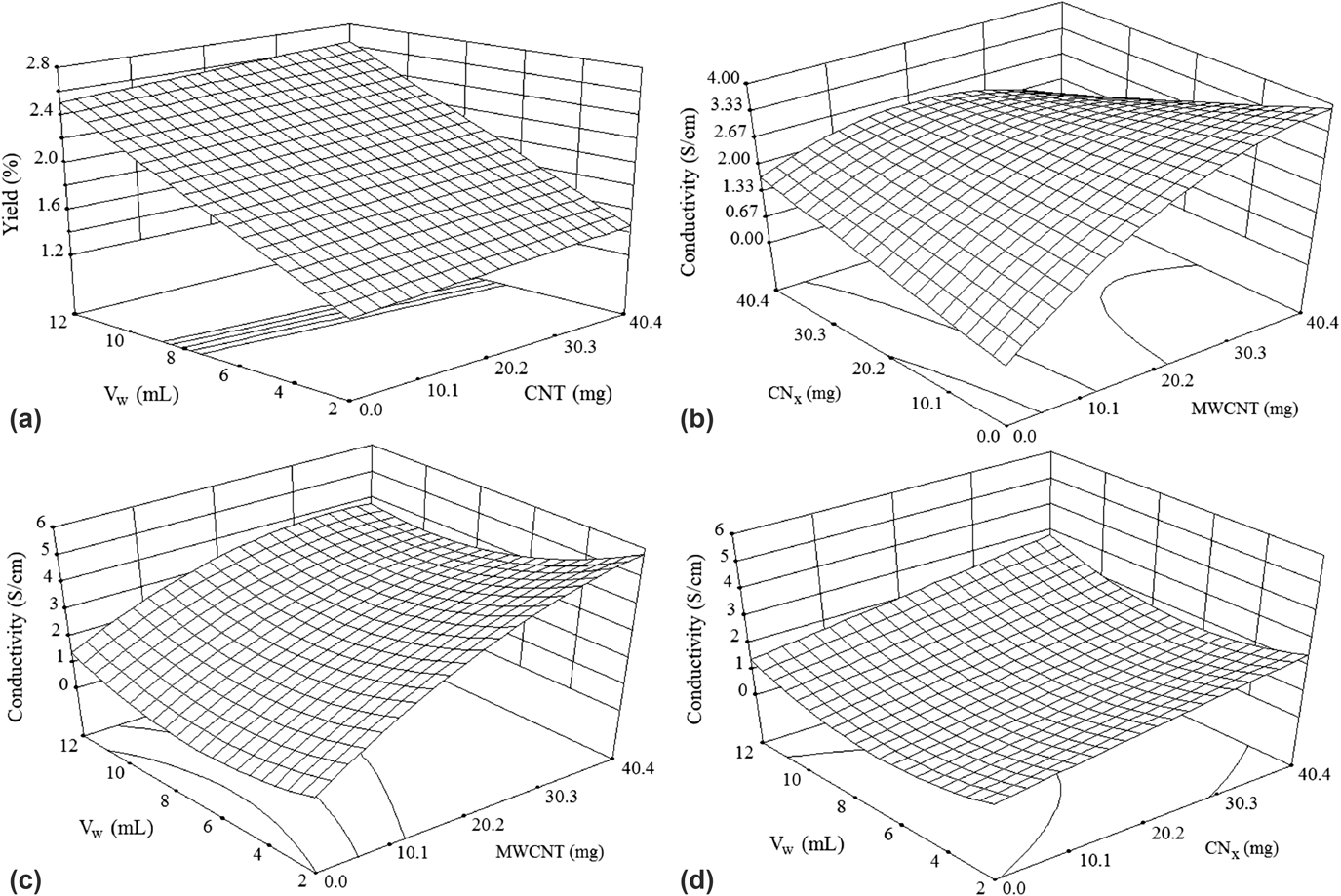
The effect of all three variables on yield and conductivity can be visualized in the RS graphs shown in Fig. 1. The yield plot, Fig. 1(a), shows an essentially flat response to amount of CNT but clearly increases with higher volumes of water. The RSs for electrical conductivity, Figs. 1(b)–1(d), confirm that increasing amounts of MWCNTs were the factor that contributed most to the nanocomposite conductivity.
RSs of yield and electrical conductivity of PAni/CNT nanocomposites. (a) Composite yield depending on total CNT weight (of either type, MWCNT and/or CNx) and V W (water volume). (b) Electrical conductivity as a function of CNx and MWCNT quantities in composites. (c) Electrical conductivity depending on MWCNT and V W. (d) Electrical conductivity as a function of CNx and V W.

Our results show that the mechanochemical synthesis of PAni is much more effective in a water-based slurry than as a dry mixture; previous studies have not considered this variable.
We think it is important to note that these hybrid materials have higher contents of CNTs than usual, and quite higher than the amounts usually required to improve mechanical or electrical properties. The materials, as produced, are friable but form a stable film over the filter membrane. They may be consolidated by post-processing steps such as dissolving in NMP or other solvents, whereupon they can also be mixed with more PAni (or other conducting polymers) and a plasticizer to form more mechanically stable materials. The solution of PAni-CNT in NMP can be cast as films, where NMP itself acts as a plasticizer, which may be useful to form actuators or other devices.Reference García-Gallegos, Martín-Gullón, Conesa, Vega-Cantú and Rodríguez-Macías42 We have proved elsewhere that masterbatches with even higher amounts of CNT (up to 80%) can result in well-dispersed composites with good dispersion of nanotubes in the matrix.Reference Espinosa-González, Rodríguez-Macías, Cano-Márquez, Kaur, Shofner and Vega-Cantú35
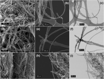
Figure 2 shows some representative SEM images and SEM/STEM pairs of the hybrid materials. In general, we observed that PAni formed irregularly shaped nanoparticles. PAni was well mixed in between the CNT; some CNTs show PAni nanoparticles adhered to their surfaces, for both the doped and undoped nanotubes, this is more evident in the SEM/STEM pairs [Figs. 2(b), 2(c), 2(e), 2(f), 2(h), and 2(i)]. The products are the combination of two nanostructures (PAni particles and nanotubes) into a hybrid material or nanocomposite but do not form a traditional composite structure with a continuous polymer matrix. In the absence of CNT, this method produces PAni in the form of nano- and microparticles, as shown in Fig. S2 in the Supplementary Material.
SEM and STEM images of CNT/PAni composites. (a, b, and c) correspond to a 49.75 wt% CNx composite. (d, e, and f) correspond to a 49.57 wt% MWCNT composite. (g, h, and i) are for a composite with 54.16 wt% CNTs (1:1 mixture of CNx/MWCNT). The darks spots seen in the STEM figures (c, f, and i) could be Fe catalyst nanoparticles from the growth of CNT, such as the encapsulated particles circled in (f), but other metal nanoparticles seem to be outside of the nanotubes, and may be particles resulting from the impact between the steel balls and the vial. In all samples PAni nanoparticles appear well mixed and dispersed. Some PAni nanoparticles adhere, to the CNT surface, with no noticeable difference in how they attach to either type of CNT.

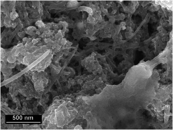
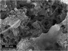
To confirm the relation between variables shown by the experimental designs, we synthesized PAni/CNx nanocomposites with a larger water volume of 17 mL. Using [FeCl3·6H2O]:[Ani·HCl] molar ratios of 2:1, the yield increased to 3.58% again confirming that water facilitates the polymerization. This sample had a conductivity of 2.23 S/cm. We also tested by increasing the ratio of oxidant to 3:1 with 17 mL of water, this increased the yield further to 4.37%. The resulting material had a conductivity of 2.14 S/cm, and it shows larger PAni particles, consistent with the higher yield, as shown in Fig. 3. The overall morphology remains similar to other samples, and CNTs are well dispersed and mixed with the polymer particles. The conductivities of these samples are in the same range as the values in Table I, even though slightly lower due to the lower amounts of CNT.
SEM micrograph of a 31.4 wt% PAni/CNx composite mechanosynthesized with a [FeCl3·6H20]:[aniline] molar ratio of 3:1 and a water volume of 17 mL.

C. Raman spectroscopy characterization
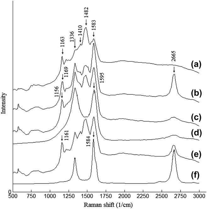
Raman spectroscopy (Fig. 4) shows the 1336 cm−1 peak of the conductive emeraldine salt form of PAni (C–N˙+ stretching of bipolaron structure).Reference Maser, Benito, Callejas, Seeger, Martínez, Schreiber, Muszinsky, Chauvet, Osváth, Kóos and Biró6,Reference Wu, Lin and Liao7,Reference Sivakkumar, Kim, Choi, MacFarlane, Forsyth and Kim10 PAni also shows a peak at 1583 cm−1; these two PAni peaks overlap with the D (“disorder”, sp 3 carbon, ∼1337 cm−1) and G (“graphitic”, sp 2 carbon, ∼1590 cm−1) peaks of CNT in the nanocomposites (curves b, c, and e in Fig. 4). In the CNx and MWCNT Raman spectra, the 2D band (2665 cm−1) appears in addition to the D and G bands (curves d and f in Fig. 4, respectively).
Raman spectrograms of (a) PAni, showing peaks characteristic of its conductive form, (b) PAni/MWCNT/CNx, (c) PAni/CNx, (d) purified CNx, (e) PAni/MWCNT, and (f) purified MWCNT. The profiles of CNx and MWCNTs are typical, with a larger ratio I D/I G for MWCNTs than CNx. The composite profiles show well-defined peaks corresponding to both the CNTs and PAni.

The 1481 cm−1 band (C=N stretching of quinoid ring), decreased in intensity in the nanocomposites. This has been reported as strong evidence of interaction of the quinoid ring of PAni with CNT surfaces.Reference Mottaghitalab, Spinks and Wallace12,Reference Cochet, Maser, Benito, Callejas, Martinez, Benoit, Schreiber and Chauvet29 The decrease in intensity of this band is negligible for PAni/MWCNT composites, and noticeable in the PAni/CNx and PAni/MWCNT/CNx composites suggesting better interaction with CNx than with undoped MWCNTs, even though electron microscopy did not show differences in how PAni particles coat the two types of nanotubes. This, however, is not definitive evidence of interaction between the two materials. Further characterization with techniques such as electron energy loss spectroscopy, or X-ray photoelectron spectroscopy, together with high resolution transmission electron microscopy (HRTEM) could provide more definitive evidence of how strong an interface can be achieved, and whether PAni is being grafted over the nanotube surface.
D. X-ray diffraction
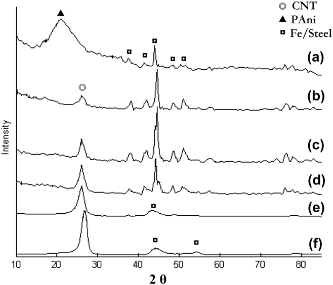
The wide XRD (X-ray diffraction) peak (2θ from 12 to 28°) in curve A of Fig. 5 shows that this mechanically synthesized PAni is noncrystalline.Reference Dallas, Stamopoulos, Boukos, Tzitzios, Niarchos and Petridis43 It is worth noting that the (002) peak of CNT does not show appreciable widening in the diffractograms of composites [Figs. 5(b)–5(d)] compared to those of purified CNx (5e) and MWCNTs (5f). This indicates that there is no significant damage to the CNT by ball milling. The wide peak of PAni is less visible in the composites, where the (002) peak of CNT has a higher intensity than the amorphous PAni; the composites also show more intense peaks from steel particles.
X-ray diffractograms of (a) pure PAni, synthesized without CNT, showing a wide peak typical of noncrystalline PAni; the peaks observed at ∼44°, come from steel particles that get ejected from the vial and mixed with the products during mechanosynthesis. (b) 49.8 wt% CNx composite, (c) 54.2 wt% CNT composite (CNx + MWCNT), (d) 49.6 wt% MWCNT composite and purified CNx (e), and MWCNT (f), which show a small peak from the Fe catalyst particles.

E. Explaining the lack of damage to CNT during ball milling
Ball milling has been reported to produce significant damage to CNT for times as short as 15 min and complete transformation into amorphous carbon in 1 h.Reference Li, Wei, Liang, Yu and Wu44 Remarkably, our SEM and XRD results did not show significant damage to the CNT. Even hand grinding MWCNTs for about 1 h in a mortar and pestle produces significant length reductions, and structural defects from damage to the walls.Reference Hilding, Grulke, Zhang and Lockwood45 This explains why in the hand-ground composites reported by Ubul et al. the MWCNT look very fragmented in TEM micrographs and their SEM images do not show long nanotubesReference Ubul, Jamal, Rahman, Awut, Nurulla and Abdiryim28 since they ground their samples for a total of 50 min.
To study further why CNTs are not damaged during the mechanosynthesis of composites, we ran two experiments without Ani·HCl. We used milling times of 20 and 60 min, 8.34 g of FeCl3, 12 mL of H2O, and 40.4 mg of CNx, given that the doped CNTs are more reactive and they would be expected to show more clearly the signs of damage. Raman spectroscopy usually provides information about mechanical or chemical damage (shown by increases in the I D/I G ratio, the relative intensities of the “disorder” and the “graphitic” peaks); however in our composite samples, the overlap of PAni and CNT bands hinders this measurement, so we relied more in electron microscopy observation for the initial evaluation.
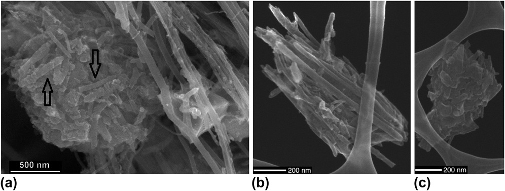
Figure 6 clearly shows that in the absence of aniline monomer, the CNTs are severely damaged. After 20 min [Fig. 6(a)], many nanotubes are fragmented, others remain long but with more irregular surfaces, some nanotubes remain apparently undamaged. The nanotube fragments show different sizes and surface appearance than the PAni nanoparticles in Figs. 2 and 3, some retain a cylindrical morphology. A steel particle is also shown in Fig. 6(a), such impurities are not uncommon in ball milling (as mentioned above, the STEM images in Fig. 2 may show some steel nanoparticles). We actually observed small increases (up to ∼4%) in the weight of CNx recovered after milling for 60 min, due to metal nanoparticles from the vial or steel balls mixing with the sample. After 60 min, only short and irregular CNT fragments are left [Fig. 6(b)], and even the cylindrical morphology appears to be lost leaving flattened irregular pieces [Fig. 6(c)].
SEM micrograph of CNx milled in water without C6H7N·HCl; (a) after 20 min several damaged nanotubes are seen forming agglomerates with some cylindrical segments visible (arrows); in the right side, a steel particle from the steel balls or vial is seen behind relatively undamaged CNT. (b) After 60 min of milling, only short and surface damaged CNTs remain and most of the CNTs appear as irregular flattened fragments (c).

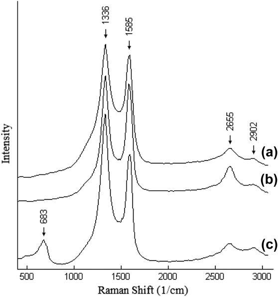
Raman spectroscopy of these blank samples (Fig. 7) shows that in the absence of aniline, the I D/I G ratio increases from 1.018 (the I D/I G of purified CNx in Fig. 5) to 1.080 after 20 min but did not increase further after 60 min of milling. In addition to increasing due to structural defects, the I D/I G ratio also increases due to functionalization, thus this result also suggests that there is likely very little oxidation of the CNT under these conditions, even after 1 h of milling. This is an advantage of our method over the use of APS, or other harsher oxidants, which can damage CNT.
Raman spectrograms of blank samples of CNx milled without aniline, with iron chloride and water for (a) 20 and (b) 60 min. The I D/I G ratio increases from 1.018 (the I D/I G of purified CNx see Fig. 4) to 1.080 after 20 min but did not increase further after 60 min of milling. Milling only purified CNx during 60 min (c) increases the I D/I G ratio to 1.349, showing that there is extensive damage by dry milling. These results indicate that the presence of water prevents the extensive damage that CNTs usually suffer under ball milling, and that FeCl3 does not cause significant oxidation of the CNT under these conditions.

To further test the hypothesis that the presence of water helps protect the CNT from damage, purified CNx were dry-milled for 60 min, without any other substance in the vial. This spectrum (curve c of Fig. 7) still shows a noticeable G peak, indicating that amorphization is not complete. It also shows a new peak at 683 cm−1, which we assume may be related to iron oxides (formed from particles ejected from the vial walls), which show distinctive signalsReference Lu and Tsai46,Reference Park, Ostrovski, Zhang, Thomson and Howe47 between 650 and 700 cm−1 but we did not explore this further. After this 60-min treatment, the I D/I G ratio increases to 1.349, noticeably higher than for wet milling. This confirms that the presence of water is an essential factor to decrease mechanical damage to the CNT during ball milling. A likely explanation for this is that water absorbs some of the mechanical energy and dissipates it during the impacts, preventing damage to the CNT. Additionally, water may act as a lubricant that allows the CNT in the slurry to be pushed aside instead of crushed between the balls and the vial. The energy from the impacts remains high enough to promote the polymerization, and adding water even increased the polymer yield as mentioned above.
IV. CONCLUSIONS
A one step mechanosynthesis of PAni/CNT nanocomposites has been developed without the use of surfactants, organic solvents, harsh oxidants, nor acids. This in situ mechanosynthesis method provides a simple and relatively fast production of PAni/CNT nanocomposites with good dispersions. Thanks to the energetic mixing provided by ball milling there is no need for sonication reducing the time and energy required for the composite synthesis.
In spite of the high mechanic energy involved in ball milling, the CNTs are not noticeably damaged. The relatively short synthesis times help avoid significant mechanical damage to the nanotubes, but the addition of water, an environmentally friendly solvent, is an important factor preventing damage. The formation of a slurry upon addition of water may help the CNT to flow away from impact zones and might also be absorbing some of the mechanical energy to prevent damage to the CNT. This does not lower the polymer yield, quite the opposite: the addition of water may be facilitating the reduction of Fe+3 by dissociating the chloride salt, and by facilitating diffusion and thus oxidation of aniline. The use of FeCl3 as the oxidant may also have the advantage of not causing significant chemical changes on the CNT, which could occur using APS or other stronger oxidants.
The resulting composites have PAni in their conductive form and the presence of CNT increases conductivity by four orders of magnitude. The conductivity appears to be higher with MWCNT than CNx; however Raman spectroscopy suggests that the nitrogen-doped nanotubes may show more interaction with PAni than the undoped MWCNT, but further characterization would be needed to explore this.
We expect that these composites might find uses in devices such as actuators, where it would be interesting to explore whether the different types of nanotubes result in differences in performance, as has been shown for PAni composites produced by a different method.Reference García-Gallegos, Martín-Gullón, Conesa, Vega-Cantú and Rodríguez-Macías42
Supplementary Material
To view supplementary material for this article, please visit https://doi.org/10.1557/jmr.2018.56.
ACKNOWLEDGMENTS
Some of the initial experimental work reported here was performed when the authors worked at the Advanced Materials Department, Instituto Potosino de Investigación Científica y Tecnológica IPICYT (San Luis Potosí, S.L.P., México) and was supported by grants CB-2008-SEP-107082 (FJRM) and CB-2008-SEP-106942, (YIVC). The authors also thank Rede NANOBIOTEC-Brasil (Edital 04/CII-2008 CAPES/MEC) for support for a postdoctoral position (JCGG) and visiting professor stays (YIVC, FJRM) at UFPE. YIVC and FJRM also thank FACEPE and PROPESQ/UFPE for additional support. YIVC and FJRM also thank the Centro de Innovación en Diseño y Tecnología (CIDyT), Advanced Manufacturing and Nanotechnlogy for Device Design groups and the Department of Sciences—Chemistry and Nanotechnology of Tecnologico de Monterrey.