I. INTRODUCTION
In recent years, nanocomposite materials attract increasing interest for the study of phase stability on the nanoscale and the design of new multifunctional materials. A nanocomposite basically consists of at least two different phases. In addition to the intrinsic physical properties of the individual components, the size of the particles, their geometrical arrangement, and the interface quality play a key role for their functional performance. This offers a unique opportunity to create new emerging properties of composites which are not present in the single components. Recently, the electrically insulating perovskite-spinel system BaTiO3-CoFe2O4 is studied quite intensively. It shows multiferroic (i.e., coupled ferroelectric-ferrimagnetic) behavior via coupling of electrostrictive and magnetostrictive strain across the interface.Reference Fiebig1, Reference Nan, Bichurin, Dong, Viehland and Srinivasan2 Nanocomposites of electrically conducting p- and n-doped components have been also fabricated for the search for highly efficient solar cell and photocatalytic water splitting devices.Reference Yang, Shtein and Forrest3, Reference Yoon, Cho, Kim, Lee, Bi, Serquis, Zhang, Manthiram and Wang4
The combination of perovskite and spinel systems seems to be particularly promising for the realization of multifunctional/multiferroic nanocomposites. These nanocomposites are typically prepared by physical or chemical vapor deposition techniques from a gaseous mixture of the various constituents. High-quality interfaces are only expected for epitaxial growth of both components which requires rather high deposition temperatures.Reference MacManus-Driscoll5 Some general rules for materials selection with respect to the formation of 3-1 compounds have been proposed.Reference MacManus-Driscoll, Zerrer, Wang, Yang, Yoon, Fouchet, Yu, Blamire and Jia6 Well-known examples of nonmiscible combinations of perovskites and spinels with this growth type are BaTiO3-CoFe2O4,Reference Zheng, Wang, Lofland, Ma, Mohaddes-Ardabili, Zhao, Salamanca-Riba, Shinde, Ogale, Bai, Viehland, Jia, Schlom, Wuttig, Roytburd and Ramesh7 BiFeO3-CoFe2O4,Reference Zavaliche, Zheng, Mohaddes-Ardabili, Yang, Zhan, Shafer, Reilly, Chopdekar, Jia, Wright, Schlom, Suzuki and Ramesh8 and BiFeO3-NiFe2O4.Reference Zhan, Yu, Crane, Zheng, Kisielowski and Ramesh9
Generally, the combined perovskite-spinel system can be written by the formula ABO3–CD2O4, where A represents a crystal site with dodecahedral oxygen coordination allowing for occupation by rather large rare-earth or earth-alkali cations. B, C, and D are crystal sites with octahedral (B, D) or tetrahedral (C) coordination to oxygen, which can be only occupied by small-sized cations like the transition metal ions Fe, Co, or Mn. Heterovalent substitution of large size A-site cations can be used for selective chemical doping. From the viewpoint of materials selection, such A-site doped transition metal oxide perovskites are of particular interest because of rich electronic ground states including different types of orbital, charge, and spin orderingReference Tokura10 and fascinating transport properties such as the colossal resistance effects in magnetic and electric fields.Reference Tomioka, Asamitsu, Kuwahara, Moritomo and Tokura11, Reference Asamitsu, Tomioka, Kuwahara and Tokura12 Furthermore, B-site substitution of transition metals can induce strong changes in conductivity mechanisms, e.g., from metal-like conductivity in La1−xSrxMnO3 to hopping conductivity of small polarons in La1−xSrxMn1−yFeyO3 (y≥0.2).Reference Zakhvalinskii, Laiho, Lashkul, Lisunov, Lähderanta, Nekrasova and Petrenko13 In the Co1−xFe2+xO4 spinel system, dependent on the Fe to Co ratio, insulating, n-type or p-type semiconducting behavior is obtained.Reference Jonker14
Specific control of doping levels in a nanocomposite is a challenging problem because of the chemical intermixing of the dopands. Selecting a rather large A cation sizes is favorable for stabilization of perovskite phase. To first order of approximation, A-site doping with large cations does not interfere with the B, C, and D site occupation, which is then governed by the thermodynamics of mixing of the small cations. The control of doping in nanocomposite thin films thus requires insights how phase formation is controlled by the complex interplay between chemical composition, stress, interfacial energies, and topology.
Here, we present a systematic study of the phase composition and nanocomposite morphology of thin films prepared by reactive ion-beam sputtering for three different B-site transition metal cations in the pseudobinary system La0.6Sr0.4BO3–CoFe2O4 (B = Fe, Co, Mn). These perovskites have been widely investigated, e.g., with respect to catalytic activity.Reference Man, Su, Calle-Vallejo, Hansen, Martinez, Inoglu, Kitchin, Jaramillo, Nørskov and Rossmeisl15 We have chosen a typical p-type doping level, where the lattice constant and the thermodynamic stability only slightly changes with the Sr content. We show that stable doped epitaxial two-phase nanocomposites can be formed in the La0.6Sr0.4FeO3–CoFe2O4 (LSFO–CFO) system. In contrast, the pseudobinary La0.6Sr0.4CoO3–CoFe2O4 (LSCO–CFO) system shows an intermediate three-phase morphology after deposition under oxygen deficient conditions. It is transformed into a stable La0.6Sr0.4FeO3–(Fe,Co)3O4 epitaxial nanocomposite after high-temperature annealing in air. The La0.6Sr0.4MnO3–CoFe2O4 (LSMO–CFO) system intrinsically shows three phases which—despite some Ostwald ripening—remain stable even after long-time high-temperature annealing in air. Due to surface precipitation and nonepitaxial growth, this system does not allow for forming an epitaxial 3-1 nanocomposite.
II. EXPERIMENTAL
The target materials for the thin film preparation were prepared by a conventional solid-state reaction procedure. Dried powders of high purity (>99.9%) La2O3, SrCO3 and Co3O4, Mn2O3, or Fe3O4 were mixed in a planetary mill, followed by an annealing step at 1000 °C in air for 24 h. Focusing on well-separated inclusions and a high density of interfaces, CoFe2O4 powder (purity>99.9995%) was added corresponding to a composition of 0.9 mol spinel per mol of ferrite and cobaltite and 0.45 mol per mol of manganite. For the La0.6Sr0.4MnO3–CoFe2O4 system, we chose the reduced ratio to obtain separation of the inclusion in this less ordered system. The spinel-perovskite composite powders were mixed, pressed into a dense disk, and annealed for 24 h at 1000 °C in air to prepare mechanically stable targets.
The thin films were prepared by means of reactive ion-beam sputtering on (001) SrTiO3 (STO) single-crystal substrates. The background pressure in the sputter chamber was better than 5 × 10⁻⁷ mbar. The noble gas working pressure (Xenon) amounted to 10−4 mbar, and an additional oxygen partial pressure of 1.4·10−4 mbar was applied to enable oxidation of the deposited film. The mean deposition rate of the composites amounted to about 4.4 nm/min, and the mean thickness of the films was ∼80 nm. The deposition temperature (T dep) was varied between 773 and 1193 K. In this temperature range single-layer epitaxial growth of CoFe2O4 and the three perovskites takes place on SrTiO3, but La0.6Sr0.4CoO3 films deposited at high temperatures reveal a volume fraction of Ruddlesden–Popper phases. Phase formation in the nanocomposites is not affected by the deposition temperature. Increasing T dep mainly results in a larger particle size and an improved particle ordering. Since the oxygen partial pressure during deposition is rather low (10−4 mbar) long-term postannealing in air at the maximum deposition temperature of 1193 K was performed in an oven to evaluate in influence on phase formation and nanocomposite stability. This is most important in the LSCO–CFO where the dependence on the partial pressure implies that the phase formation is strongly affected by the method of preparation.
Scanning electron microscopy (SEM) imaging of the samples was performed in a Zeiss LEO SUPRA 35 microscope system (Oberkochen, Germany). X-ray diffraction (XRD) measurements were carried out in a Siemens D500 device (Munich, Germany) and a Philips X’Pert (Eindhoven, Netherlands), both equipped with a Co source (λCo = 0.170921 nm). Using electron-transparent samples prepared by focused ion-beam etching, cross-sectional transmission electron microscopy (TEM) investigations were performed at a Philips CM30 (Eindhoven, Netherlands). We also used energy-dispersive x-ray analysis in scanning transmission electron microscopy (STEM-EDX) as well as bright- and dark-field imaging in a Philips CM12 microscope (Eindhoven, Netherlands).
III. RESULTS
A. Stable two-phase nanocomposite formation in the system LSFO–CFO
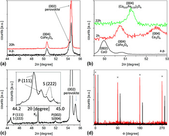
The XRD spectra of a thin film nanocomposite deposited from a target with a nominal composition LSFO–CFO is shown in Fig. 1(a). Only (004) spinel and (002) perovskite reflections close to the (002) STO substrate reflection are observed. The deposited film reveals the commonly observed epitaxial growth directions of spinel-perovskite composites on (001) STO substrates,

X-ray diffraction of the thin film nanocomposites deposited at 1193 K and after additional heat treatment at the same temperature in air. (a) Pseudobinary system: La0.6Sr0.4FeO3–CoFe2O4 (LSFO–CFO) (a.p. and after 20 h of postannealing). (b) Pseudobinary system: La0.6Sr0.4CoO3–CoFe2O4 (LSCO–CFO) (a.p. and after 2 h/22 h of postannealing. (c) Pseudobinary system: La0.6Sr0.4MnO3–CoFe2O4 (LSMO–CFO) (after 20 h of postannealing). Inset: Detail scan in the vicinity of the P (111) periclase/S (222) spinel reflection with Ka1-Ka2 splitting. (d) (202)-Φ-scans of the Co,Fe spinel inclusions in the LSFO–CFO (marked by crosses) and the LSCO–CFO system after postannealing for 20 h (22 h). The scans are shifted by 10° for clarity. The pronounced fourfold symmetry demonstrates the epitaxial growth.

as confirmed by electron diffraction in cross section and by the (202)-Φ-scan [Fig. 1(d)].
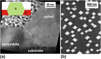
The chemical composition of the two observed phases in the nanocomposite film was analyzed by EDX mapping in TEM. The cross-section view on the film shows Co- and Fe-rich spinel inclusions embedded in a La-, Sr-, and Fe-rich perovskite matrix with a negligible small Co-content (x Co < 0.5%). The combined x-ray and TEM analysis reveals that a doped two-phase perovskite-spinel nanocomposite is formed with a chemical distribution of the constituents and thus complies with the nominal target composition. The height of the CFO inclusions is roughly twice of the perovskite layer thickness. The terminating crystallographic planes are (001) on the top and the bottom, whereas the side-planes to the vacuum (upper half of the inclusion) and to the perovskite matrix (lower half of the inclusion) are formed by (111) crystal planes [Fig. 2(a)].
Stable two-phase composite LSFO–CFO deposited at 1193 K. (a) Cross-sectional high-resolution transmission electron microscopy (TEM) bright-field image. A protective Pt layer (FIB Pt) was deposited on top of the sample to avoid irradiation damaging during focused ion-beam etching. The inset schematically shows the shape of the spinel inclusions S in the perovskite matrix P. (b) Scanning electron microscopy (SEM) top-view image.

This geometric form of the inclusions gives rise to square-shaped structures in plan-view SEM images [Fig. 2(b)]. A preferential arrangement of the inclusions along the (110) in-plane direction of the STO substrate is observed with a rather narrow particle size distribution. The mean particle size of about 150 nm, the particle arrangement, chemical composition as well as crystallographic orientations are practically unaffected by an additional heat treatment for 20 h at the deposition temperature (T dep = 1193 K) in air.
B. Intermediate three-phase nanocomposite formation in the system LSCO–CFO
Starting from a nominal LSCO–CFO composition, the most striking difference to the LSFO–CFO system is the appearance of a third phase with periclase structure. It is observed at all selected deposition temperatures between 1053 and 1193 K under pO2 = 1.4 × 10⁻⁴ mbar via XRD reflections [Fig. 1(c)] and is confirmed by electron diffraction.
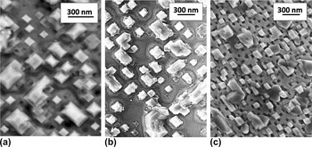
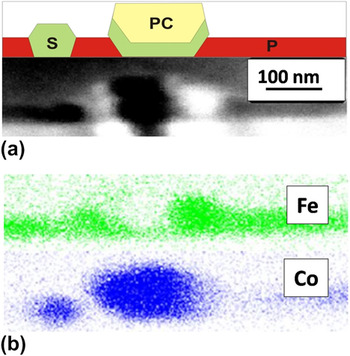
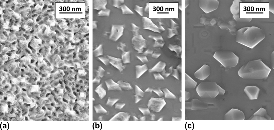
SEM inspection shows two types of inclusions [Fig. 3(a)]: small particles which resemble to the inclusions in the LSFO–CFO system and large rectangular shaped particles. EDX mapping in cross-sectional STEM investigations (Fig. 4) shows that the perovskite matrix consists of LSFO (x Co < 0.5%) and the small inclusions are composed of CFO. In contrast, the larger inclusions appear to be formed by a CFO outer-shell and an embedded Co-rich phase. These results indicate that the initial pseudobinary LSCO–CFO phase composition in the target is not stable but transformed into a LSFO–CFO nanocomposite. Under oxygen deficient conditions, the resulting large Co-excess is incorporated into the formation of a CoO type periclase structure.
SEM top-view image of the LSCO–CFO composite (a) as-prepared at T dep = 1193 K, (b) after 2, and (c) after 22 h of postannealing at T pa = 1193 K.

Cross-section of the LSCO–CFO composite a.p. at T dep = 1193 K. (a) Scheme of the inclusion shapes and TEM bright-field image. (b) Corresponding Co and Fe EDX mapping. The small inclusions consist of CFO spinel (S), whereas in the large inclusions, CoO (PC) is embedded in CFO forming the interface to the perovskite matrix.

Phase formation and particle morphology are strongly affected by postannealing in air. After 2 h at 1193 K, the CoO is oxidized to Co3O4. Co3O4 phase disappears after additional 20 h of heat treatment at 1193 K and only a single spinel phase is observed [Fig. 1(c)]. The shape of the inclusions reflects the phase transition. Starting from the bi-modal size distribution of the as-prepared samples [Fig. 3(a)], the treatment for 2 h results in the formation of rectangular outgrowths at the inclusions with edges parallel to the (100) and (010) substrate directions, respectively [Fig. 3(b)]. After long-term annealing, the outgrowths are almost suppressed and small and rather regular square-shaped inclusions are observed. A significant number of large irregular particles are still present [Fig. 3(c)]. Nevertheless, (202)-Φ-scan of the spinel inclusions [Fig. 1(d)] indicates the epitaxial relation between the spinel particles and the embedding perovskite matrix.
C. Intrinsic three-phase nanocomposite formation in the system LSMO–CFO
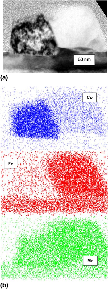
For the nanocomposite formed in the pseudobinary LSMO–CFO system, XRD investigations indicate the formation of three phases [Fig. 1(c)]. An epitaxially grown perovskite phase is present, but two additional reflections close to 2⋅Θ = 44.5° and 52° are visible. A detailed scan close to 44.5° is shown in the inset: the two reflections (with Kα1/Kα2 splitting) can be attributed to (111) periclase and (222) spinel. In addition, the presence of a (333) reflection (not shown) confirms the formation of a spinel phase because this reflection is forbidden in the periclase structure. TEM inspection of the thin films grown at two different deposition temperatures shows drastic differences in the nanocomposite morphologies between the two films. At high deposition temperatures (T s = 1193 K), the nanocomposite consists of a perovskite matrix with truncated pyramid particles almost entirely located on top of the matrix [Fig. 5(a)]. Electron diffraction and EDX mapping demonstrate the presence of the following three phases: A La0.6Sr0.4BO3 perovskite matrix with a negligibly small Co-content and a Fe to Mn ratio of about 1. The particles are formed by two different Mn, Co, Fe phases with Mn to Fe(Co) ratios of 2.8(1.4) and 1(2), respectively. The uncertainty in composition is about 10% [Fig. 5(b)]. Because of similar diffraction patterns of spinel and periclase and lifting of extinction rules for reflexions due to multiple scattering processes, a distinction between those two structures in the TEM is not possible.
Cross-section of the LSMO–CFO composite deposited at 1193 K. (a) TEM bright-field image of a surface precipitate. (b) Corresponding Co, Fe, and Mn EDX mapping. Most probably, the Co-rich phase is periclase and the Fe-rich phase is spinel.

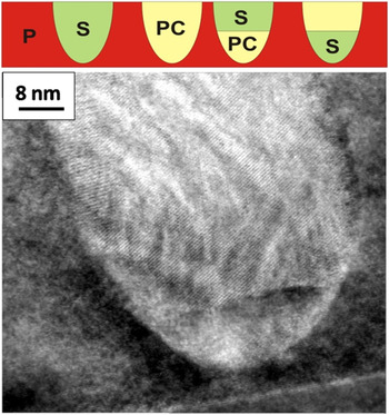
In contrast to the three-phase system grown at higher T s, where the nonperovskite particles are pushed to the surface of the perovskite, the three-phase system deposited at 1133 K exhibits almost embedded particles which can either consist of the Fe-rich, of the Co-rich, or of a mixture of both phases (Fig. 6).
Cross-sectional high-resolution TEM bright-field image of LSMO–CFO composite deposited at T dep = 1133 K with a spinel inclusion. As schematically shown, the inclusions are completely embedded in the perovskite matrix (P) and consist of the spinel phase (S), the periclase phase (PC), or a mixture of both.

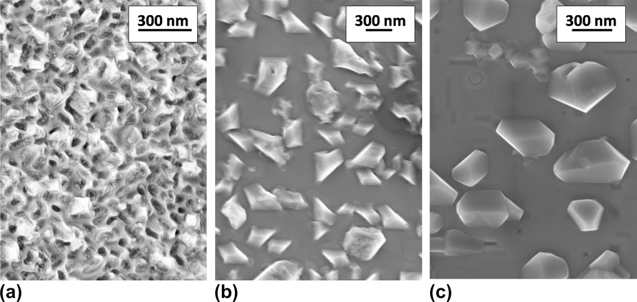
The top-view inspection via SEM (Fig. 7) shows that the particle arrangement and the size distribution are almost irregular at low T s. With increasing T s or after postannealing, a tendency of ordering in particle shape and distance is observed, which is accompanied by the crossover from embedded particles arrangements to surface precipitates [Figs. 7(b) and 7(c)]. Particle arrangement and size distribution become more regular without a pronounced Oswald ripening process.
SEM top-view image of the LSMO–CFO composite (a) as-prepared at T dep = 1133 K, (b) as-prepared at T dep=1193 K, and (c) after additional heat treatment for 20 h 1193 K.
D. Strain state of the nanocomposites
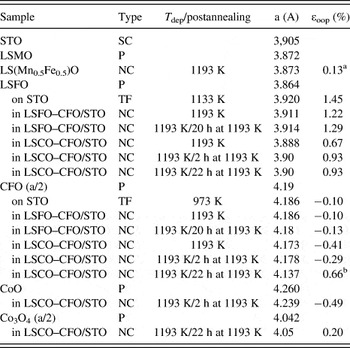
Epitaxial growth is typically accompanied by substantial strain in the deposited film due to substrate clamping. It is interesting to notice that combining LSFO and CFO to a nanocomposite does not significantly alter the strain state compared to the strain state observed in planar thin films of the single components. An overview on the observed out-of-plane strain in planar thin films and nanocomposites is given in Table I. LSFO films on STO reveal an elongation of the out-of-plane lattice parameter (ε oop = 1.45%). This is in contrast to the expected tensile strain (ε oop < 0), which follows from the bulk lattice constants (aLSFO < aSTO), a positive Poisson ratio and the observed coherent interface to the substrate. Out-of-plane lattice expansion is, however, a common feature of ion-beam sputtered films, where the stress state is dominantly controlled by preparation-caused defects. Embedding of CFO particles in the LSFO matrix only results in a small strain relaxation (ε oop ≈ 1.3%).
Lattice constant a and residual out-of-plane strain ε oop of some of the involved phases deduced from the position of the respective x-ray diffraction reflections.

ε oop is calculated from (aexp − abulk)/abulk. The column “Type” reveals the sample type, i.e., powder (P), single-crystal (SC), thin film (TF) and nanocomposite (NC). For noncubic perovskites, the lattice constants are given in the pseudocubic notation. The specified values for spinels correspond to the half lattice constant.
a The lattice constant of the solid solution La0.6SrO.4Mn0.5Fe0.5O3 perovskite was estimated to 3.87 A from the lattice constants of LSMO and LSFO according to Vegard’s law.
b The lattice constant of the solid solution (Co,Fe)3O4 spinel was estimated to about 4.11 A for (Co0.67Fe0.33)3O4 from Ref. Reference Roiter and Paladino16
Planar CFO films on STO as well as CFO in the LSFO–CFO nanocomposites are almost unstrained (ε oop ≈ 0.1%). High-resolution TEM images and RHEED investigations (not shown here) clearly indicate the presence of misfit dislocations, formed after nanocomposite deposition of only 2 nm. This is in accordance with the critical thickness observed in Ref. Reference Axelsson, Aguesse, Spillane, Valant, McComb and Alford17.
In the as-deposited LSCO–CFO system, incorporation of a third phase, CoO, in the CFO particles significantly changes the strain state. In comparison to the LSFO–CFO composite, the strain is lower in the perovskite but higher in the CFO within the two-phase CoO/CFO inclusions.
Detailed determination of the strain state in the LSMO–CFO nanocomposites require knowledge of the various solid solution bulk lattice constants, which is presently absent. However, assessment of the bulk lattice constant according to Vegard’s law implies that the perovskite is in a low strain state. Mn substitution of Co and Fe in CoFe2O4 causes an increase of the lattice constant,Reference Kim, Kim, Park and Park18 and, therefore, a larger mismatch to the underlying STO substrate.
IV. DISCUSSION
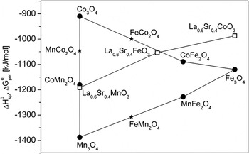
Since the typical formation enthalpies of the involved spinels and perovskites are not very different (see Fig. 8),Reference Kubaschewski, Alcock and Spencer19–Reference Calle-Vallejo, Martínez, García-Lastra, Mogensen and Rossmeisl21 the prediction of the equilibrium phases of the multicomponent nanocomposites requires detailed knowledge on the temperature- and pressure-dependent phase diagrams. However, some basic considerations allow for qualitative understanding. It is obvious from Fig. 8 that our observation of the high stability of the perovskite phase is not reflected in their free formation enthalpies. But from the viewpoint of Pauling’s rules, large A cations favor an oxygen configuration polyhedron with a high coordination number like the dodecahedral oxygen coordination in the perovskite structure. In all three considered pseudobinary systems, the perovskite structure is single phase and no large size A cations are incorporated into the spinel or periclase structures. This emphasizes the prominent role of the perovskite crystal structure for incorporation of large-size A cations. In contrast, the spinel structure offers a large number of tetrahedral and octahedral sites to incorporate the small-sized cations. However, other crystal structures such as the periclase structure also offer the same opportunities, and the Gibbs phase rule allows the formation of more than two phases. In the LSFO–CFO system, the only degree of freedom is a Fe–Co exchange between perovskite B sites and spinel C and D sites. Comparing the formation enthalpies ΔH0 (or ΔG0, see Fig. 8), the following relations hold:

Standard enthalpies of the spinels ΔH0 and free enthalpies of perovskites ΔG0 for formation from the elements at room temperature.Reference Kim, Kim, Park and Park18, Reference Kubaschewski, Alcock and Spencer19, Reference Navrotski and Kleppa20 The star symbols correspond to spinel formation enthalpies calculated from A3O4 + AB2O4 → 2·BA2O4, i.e., by disregarding mixing contributions. The lines are guide to the eye. Note that the ΔG0 of perovskites are calculated by DFT and are about 70 kJ/mol larger than the experimental values.Reference Calle-Vallejo, Martínez, García-Lastra, Mogensen and Rossmeisl21 At room temperature, the contribution from formation entropy T⋅ΔS0 is of the same order,Reference Cheng and Navrotsky22 i.e., ΔGDFT ≈ ΔH0.

Consequently, the formation enthalpies of the involved phases do not suggest a pronounced trend of Co/Fe cation exchange between the perovskite and spinel structures.
The remarkable stability of this combination is directly demonstrated by incorporating a pronounced Co access, i.e., starting from a nominal composition of LSCO and CFO. Again, a LSFO–CFO nanocomposite is formed. The phase formation appears to be dominantly driven by the ferrate perovskite because the resulting evolution of phase composition of Co-rich spinel structures directly reflects the Co–Fe–O pT-phase diagram at T = 900 °C and a nominal Co/Fe ratio of ∼2.Reference Jung, Decterov, Pelton, Kim and Kang23 Due to the low oxygen partial pressure during deposition, a phase mixture of CoFe2O4 and CoO is formed. Post-treatment in air results first in oxidation of CoO to Co3O4, and finally, in the formation of a single phase (Co2/3Fe1/3)3O4 spinel.
In contrast, the LSMO–CFO system is not simply governed by the perovskite formation. The comparison of formation enthalpies from Fig. 8 gives


i.e., significant Mn exchange between the perovskite and spinel phase can be only driven by the reduction of the ΔH0 for Mn-rich spinels. At a Sr content of 0.4, LSFO, LSCO, and LSMO form solid solutions over a large composition range.Reference Filonova, Demina, Kleibaum, Gavrilova and Petrov24, Reference Aksenova, Anan’ev, Gavrilova and Cherepanov25 Experimentally, in the pseudobinary LSMO–CFO system, we observe the formation of a (Fe, Mn) solid solution on the B-site of the perovskite structure which coexists with two Mn-rich spinel and periclase oxide phases. This seems to agree with the finding of Subramanian and Dieckmann, that in addition to the spinel structures, the Mn–Fe–Co–O system reveals also rock salt as well as corundum phases depending on the oxygen partial pressure.Reference Subramanian and Dieckmann26 At the observed chemical composition of our LSMO–CFO nanocomposite, a phase separation into a Co-rich periclase and a Fe-rich spinel phase is expected. This indicates that the Mn∼0.45Co∼0.2Fe∼0.35Oy oxide is the spinel and the Mn∼0.45Co∼0.35Fe∼0.2Oy is the periclase phase.
The three different nominal target compositions also result in quite different particle shapes and arrangements. Thermal equilibrium states of nanocomposites are not only affected by chemical composition but also by interfacial contributions, i.e., the chemical interfacial energy and the elastic strain energy. The latter depends on substrate clamping and mutual lattice matching of the composite-forming phases.Reference MacManus-Driscoll, Zerrer, Wang, Yang, Yoon, Fouchet, Yu, Blamire and Jia6 Competition between interfacial energy and elastic strain energy sensitively depends on the presence and density of misfit dislocations ranging from coherent interfaces with small interfacial energies (≈0.1 J/m2) and rather large strain contribution to incoherent interfaces with high interfacial energies (≈1 J/m2) but small strain contributions.Reference Kaul, Gorbenko and Kamenev27 These interfacial energy contributions are expected to play a dominant role in controlling the equilibrium shape of the particles.
In the LSFO–CFO system, the CFO particles reveal an equilibrium shape [Fig. 2(a)], which is expected from the interfacial energies by means of the Winterbottom construction.Reference Zheng, Zhan, Zavaliche, Sherburne, Straub, Cruz, Chen, Dahmen and Ramesh28 Strain effects seem to play a minor role with respect to particle shape, but most likely, self-assembly of the island arrangement takes place via a substrate-mediated elastic interaction between the islands along soft directions of the substrateReference Shchukin and Bimberg29 [Fig. 2(b)].
Due to the high deposition temperature particle size and particle distance are rather large. We have focused this study to rather small film thickness which exhibit nucleation controlled three-dimensional growth. Consequently, the inclusions are only partly embedded. A crossover to a columnar growth requires much thicker films. The facets of the CFO inclusion are smooth and have well-defined crystallographic orientations. In contrast, the surrounding perovskite matrix reveals a pronounced surface roughness. Ion-beam sputtering of perovskite films typically results in very smooth surfaces, allowing, e.g., in LSMO the observation of unit-cell surface steps of the underlying substrate. Deposition or postannealing at high temperature frequently gives rise to a pronounced crystallographically orientated surface roughening. This effect is most pronounced in the LSFO–CFO and the LSCO–CFO system (Figs. 2, 3). For the LSMO–CFO system (Fig. 7), only a few dents are visible. Most of the perovskite matrix reveals a surface roughness of a few nm deduced from AFM investigations.
The different contributions from the perovskite and the inclusions to the total strain energy might be roughly estimated by taking into account the volume fractions of the different phases and the Young’s moduli of CFO (∼190 GPaReference Li, Fisher, Liu and Nevitt30), CoO (∼200 GPaReference Sumino, Kumazwa, Nishizawa and Pluschkell31), Co3O4 (∼125 GPaReference Varghese, Zhang, Dai, Tan, Lim and Sow32), and of LSFO or LSMO perovskites (∼130 GPaReference Orlovskaya, Anderson, Brodnikovskyy, Lugovy and Reece33, Reference Rajendran, Kumaran, Sivasubramanian, Jayakumar and Raj34).
In the LSFO–CFO system, the strain energy is mainly caused by the perovskite matrix, i.e., the contribution of the CFO inclusions is negligible. The main difference between the LSFO–CFO and the LSCO–CFO system is the appearance of substantial strain in the spinel and periclase inclusions, i.e., the portion from matrix and inclusions is similar. A coarse estimate shows that the total strain energy is roughly a factor of two lower in the LSCO–CFO system. Since the lattice constants follow the relation aLSFO < aCFO/2 < aCoO, the embedding of the CoO phase inside the CFO particles in as-deposited nanocomposites seems to be a path to avoid the formation of highly stressed CoO/LSFO interfaces. This is accompanied by a substantial reduction in total strain energy.
Oxidation of CoO to the Co3O4 spinel during postannealing significantly increases the perovskite contribution to strain and decreases the contribution of the inclusions. This seems to keep the total strain energy almost unchanged. Since the lattice constant of Co3O4 is smaller than the lattice constant of CFO, the Co3O4 phase tends to form outgrowth with interfaces to the perovskite phase [Fig. 3(b)]. Establishing chemical equilibrium by the formation of the solid solution spinel after long-term annealing, the total strain energy is comparable to those in the LSFO–CFO system, but with similar portions from matrix and inclusions.
To some extent, the phase formation in the intrinsic three-phase LSMO–CFO system resembles the intermediate three-phase LSCO–CFO system. The most striking difference is the pronounced trend to surface segregation, embedding of the inclusions is only observed at low deposition temperatures. In principle, such a process might be driven by large interfacial energies between the perovskite and the periclase/spinel phases. However, the system tends to form solid solutions in which significant contents of Fe and Mn are present in all three phases almost excluding high interfacial energies. In addition, the surface precipitates reveal a truncated pyramid shape, where the bottom faces are larger than the top faces. This is in contrast to a nonwetting configuration.
Mn substitution in Co,Fe spinel and periclase phases significantly increases the lattice mismatch to perovskite phases. In the nanocomposite, the spinel and periclase phases reveal a preferred (111) growth direction in a low strain state with incoherent interfaces to the perovskite. In addition, highly strained surfaces are instable with respect to stress-lowering surface roughening.Reference Srolovitz35 Most likely, the surface segregation and the nonepitaxial growth in the LSMO–CFO system is due to the larger lattice mismatch in comparison to the LSFO–CFO system.
In summary, the freedom of choice in combining perovskites with CoFe2O4 in nanocomposite films by decomposition from the vapor phase is strongly limited by the possibility of transition metal cation exchange on the B, C, and D sites, respectively. Since the enthalpies for oxide formation from the metal elements are comparable, Gibbs phase rule would allow the phase coexistence of more than three phases. However, two factors strongly favor the formation of a single perovskite phase: (i) The presence of large-size A cations which tend to dodecahedral oxygen coordination, and, (ii) the large solubility ranges of perovskites with respect to B site substitution by transition metals. The off-stoichiometry induced by the exchange of the B site element is balanced by the formation of C1+xD2−xO4 solid solutions. The presence of oxygen pressure dependent miscibility gaps in the quaternary Co–Mn–Fe–O systemReference Subramanian and Dieckmann26 favor phase formation into periclase/spinel composites. This basically rules out the possibility of fabrication of two-phase nanocomposites in the system LSMO–CFO via spontaneous decomposition.
However, solid solutions of transition metal cations also give rise to new opportunities in design of nanocomposites. In the LSFO–CFO system, conductive AFM measurements show high conductivity in the perovskite matrix and insulating behavior of the CFO particles. This offers the opportunity of CFO doping by forming a solid solution (Co,Fe)3O4 spinel. In addition, the introduction of a large Co-excess can give rise to the incorporation of CoO or Co3O4 particles, where both systems are of high interest for catalysis.
Misfit strain to the substrate and formation of a third phase substantially alter the inclusion topology, ranging from embedded particles to surface precipitates strongly affected by the deposition temperature and/or postannealing. Residual strain is always present in nanocomposites and is, most likely, responsible for topological stability and instability of nanocomposites under thermal treatments.
ACKNOWLEGMENT
This work is supported by the Deutsche Forschungsgemeinschaft under grant numbers JO 348/8 and SFB 602, which is gratefully acknowledged.