Introduction
The increasing demands for higher data rates, broader coverage, and enhanced communications reliability call for significant advancements in radio technology [Reference Zheng, Wang, Yang, Yu, Lai, Huang, Feng, Wang, Li and Zhong1]. As one of the most promising technologies massive multiple-input multiple-output (MIMO) systems have attracted significant interest in both the industry and academic in 5G new radio (NR) [Reference Larsson, Edfors, Tufvesson and Marzetta2–Reference Wiesmayr, Cammerer, Aoudia, Hoydis, Zakrzewski and Keller4]. Radio channel modeling is crucial for the development and assessment of NR technologies. Empirical data have shown that massive MIMO systems exhibit distinctive features not typically found in traditional MIMO setups, such as spatial non-stationarity and the prevalence of spherical wave propagation [Reference Huang, Feng, Sun, Wang, Zhang and Yang5, Reference Yuan, Zhang, Ji, Pedersen and Fan6].
Coexisting with the high attenuation and scarcity of propagation paths associated with millimeter waves (mmWave), it is essential to integrate massive MIMO technology with mmWave systems to unlock their full potential [Reference Tian, Yin, Dupleich, Müller, Schneider, Thomä, Barbiroli and Zoli7–Reference Hu, Hong and Jiang9]. The integration of massive MIMO technology significantly enhances the energy and spectral efficiency of the communication channel [Reference Ngo, Larsson and Marzetta10, Reference Hu, Zhan, Jiang, Yu and Hong11]. It also provides substantial beamforming benefits and effectively decreases the path loss associated with mmWave channels, as discussed in Refs [Reference Zhang and Fan12, Reference Yin, Yu, Yu, Jing, Zhu, Hong and Zhu13]. Additionally, mmWave technology inherently provides a greater bandwidth, as noted in Ref. [Reference Huang, Zhang, Gao and Feng14]. The utilization of these shorter wavelengths facilitates the installation of a large size of antenna array in the compact form factor [Reference Huang, Feng, Sun, Wang, Zhang and Yang5].
The implementation of massive MIMO systems has been widespread, accompanied by extensive research into channel modeling. Artificial intelligence (AI) radio maps for channel prediction have been in the spotlight recently [Reference Liu and Chen15]. By acquiring information about the communication environment, it is crucial for the network design of communication systems, and ray tracing (RT) can be one of the important steps. RT stands out as a prevalent simulation technique for studying the propagation of electromagnetic waves. It is grounded in the principles of geometric optics and typically incorporates a combination of shooting and bouncing rays along with the images theory, positioning it as a favored option for channel modeling in both indoor and outdoor mmWave environments [Reference Tian, Yin, Dupleich, Müller, Schneider, Thomä, Barbiroli and Zoli7, Reference Karstensen, Fan, Carton and Pedersen16]. Specifically, when dealing with target dimensions that are more larger than the wavelength, RT becomes an essential and reliable tool in wireless communication system simulation [Reference Xu and Huang17–Reference Hofmann, Schwind, Bornkessel and Hein19]. It can help alleviate the requirement for costly and time-consuming channel measurements and simplifies scenario modeling.
The aim of this paper is to confirm the accuracy of the channel data generated by the RT for massive MIMO systems in the mmWave frequency range, especially in an indoor scenario that exhibits more complex multipath propagation than the outdoor scenario and hence is challenging for RT. To achieve this goal, the channel measurement for massive MIMO is conducted using a vector network analyzer (VNA)-based channel sounder as proposed in the study referenced in [Reference Mbugua, Fan, Olesen, Cai and Pedersen20]. The experimental setup utilizes a virtual uniform circular array (UCA), operating with a 6 GHz bandwidth at a central frequency of 29.5 GHz, as detailed in Ref. [Reference Yuan, Zhang, Ji, Pedersen and Fan6]. The identical scenario is then simulated by the RT. A comparative analysis is performed, focusing on channel impulse responses (CIRs) obtained from various locations within the virtual UCA and investigating the beamforming results. Additionally, the potential of using simulation results in MIMO detection is explored. The key contributions of this paper are outlined below.
(1) A virtual array scheme, forming a UCA with a 0.5 m radius and 720 antenna elements, is implemented to measure mmWave channels covering the frequencies of 26.5–32.5 GHz. Propagation characteristics of large-scale array antennas are analyzed employing classical beamforming (CBF) algorithms.
(2) An RT simulation with the same scenario and configurations as the measurement is performed, predicting the mmWave massive MIMO channel. The effect of interaction order on mmWave CIR is discussed to reduce the use of simulation arithmetic resources. It is established that in this scenario, interaction order up to the third order can provide a complete description of the main path in the investigated scenario.
The paper is organized as follows: the second section describes the CBF algorithm employed to analyze UCA arrays. The third section describes the measurements set up and the scenario. The fourth section discusses the RT simulation and the modeling of the scenario. The fifth section provides a complexity analysis by comparing the results obtained through the experiments and simulations. Finally, the sixth section concludes this article.
Indoor scenario channel model
Signal model
Figure 1 illustrates a UCA consisting of P array elements that are evenly distributed along the circumference of a circle with a radius r. Each element is positioned at an angle  $\theta _{m} = 2\pi \cdot m/P$ with
 $m\in \left [ 1, P \right ]$. Considering N distinct paths from the receiver (Rx) to the transmitter (Tx) at the center of the UCA, the channel’s frequency response can be described as follows:
 \begin{equation}
H_{c} \left ( f \right ) = {\textstyle \sum_{n=1}^{N}} a_{n} exp\left ( -j2 \pi f\tau _{n} \right )
\end{equation}
Illustration of the virtual UCA, with mth element, nth path.

where an and τn represent the complex amplitude and delay of the nth path, respectively .
Considering the channel frequency response for N distinct paths between the Rx and each individual element of the UCA at the Tx location:
 \begin{equation}
H_{m} \left ( f \right ) = {\textstyle \sum_{n=1}^{N}} a_{n} \text{exp} \left ( -j2 \pi f\tau _{m} \right )
\end{equation}
τm represent the delay of the nth path on each antenna elements. The delay difference between nth path reaching mth element and the center of the UCA can be calculated from the antenna geometrical location properties.
The phase alignment of the antenna array elements is achieved through the application of a weighting function, which is represented as follows:
 \begin{equation}
w_{m} = \text{exp} \left ( -2\pi f\cdot \frac{r\cdot \cos \left ( \theta- \theta _{m} \right ) }{c} \right )
\end{equation}
The classical beamforming result can be obtained by:
 \begin{equation}
H\left ( f,\theta \right ) =\frac{1}{P} {\textstyle \sum_{p=1}^{M}} w_{m} \cdot H_{m} \left ( f \right )
\end{equation}
Then, the CIR of the delay-angular domain can be calculated via inverse Fourier transformation.
 \begin{equation}
h\left ( \tau ,\theta \right ) = {\textstyle \sum_{f_{L}}^{f_{U}}} H\left ( f,\theta \right ) \text{exp} \left ( j2\pi f\tau \right )
\end{equation}
fU and fL are the upper and lower limits of the frequency band.
Channel measurements and results
Measurement architecture
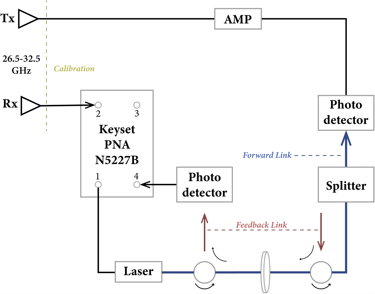
The experimental arrangement includes a set of vertically polarized omnidirectional biconical antennas, as referenced in [Reference Zhekov, Tatomirescu and Pedersen21] and [Reference Fan, Carton, Nielsen, Olesen and Pedersen22], which serve as the Tx and Rx units. Figure 2 depicts the phase-compensated VNA-based channel sounder as proposed in Ref. [Reference Mbugua, Fan, Olesen, Cai and Pedersen20]. The system operates within a frequency band of 26.5–32.5 GHz, offering a 6 GHz bandwidth. It employs 1800 frequency points across this range, which results in a delay resolution of 0.167 ns and allows for the measurement of propagation distances up to 90 m. The calibration between transceiver antennas is performed in advance of measurements. The CIR can be derived by conducting an inverse Fourier transform on the CFR in the frequency domain. In the virtual UCA configuration, the transmitter encompasses 720 distinct positions. Additionally, a turntable is set up to rotate through 360 degrees in a clockwise direction, with increments of 0.5 degrees, as illustrated in Figure 3. The detailed measurement parameters are shown in Table 1.
Block diagrams of the VNA-based channel sounder in Ref. [Reference Mbugua, Fan, Olesen, Cai and Pedersen20].

(a) Measurement scenario and (b) photo of the indoor scenario for two antennas location [Reference Di, Yuan, Lyu, Zhang and Fan23].

Measurement specifications

Channel measurements
The measurement scenario is located on the ground floor of a building in the Aalborg University, Aalborg, Denmark. The dimensions of the enclosed room are  $8.19\times 4.78\ \mathrm{m}^2$, as shown in Figure 3. In this scenario, several structural elements possess significance for RT simulations. Notably, the room is characterized by two floor-to-ceiling glass windows, an elevator, two heaters, and two wooden doors, all of which serve as critical constituents within the simulated model. Two omnidirectional bi-conical antennas are used as the Tx and Rx, with 1.25 m of the antennas above the ground. To enable the distinction of propagation paths characterized by various time delays originating from reflections of the room’s left and right boundaries, the Tx and Rx positions are strategically placed in proximity to the left wall, with a distance of 2 m. This configuration yields a deliberate line-of-sight (LoS) scenario, where the Tx and Rx are separated by a linear distance of 6.5 m. For more technical details of the measurement campaign, readers are recommended to read [Reference Yuan, Zhang, Ji, Pedersen and Fan6].
Ray tracing simulation
Ray tracing modeling
The scenario is simulated utilizing an in-house RT, which is based on the principles of geometric optics. RT assumes that light travels in straight lines (rays) and interacts with surfaces through transmission, reflection, diffraction, and scattering. Although a vegetation model is typically used for outdoor environments, it is excluded from this indoor simulation. The workflow of RT simulation contains (a) Scenario Definition (material definition), (b) 3D Geometry Modeling (in blander), (c) Simulation Launching, and (d) Channel Model Virtualization. The LoS components within the RT are determined according to the Friis free-space path loss formula, and reflections are figured out using Snell’s equation, as in Ref. [Reference Molisch24]. The diffraction calculations are grounded in the uniform geometrical theory of diffraction (UTD) [Reference Andersen25–Reference Na and Eibert27], and scattering is evaluated using the Lambertian, directive, and backscattering lobe scattering models [Reference Degli-Esposti, Fuschini, Vitucci and Falciasecca28]. Thus, the accuracy of the indoor model’s geometry and the specifications of the building materials are pivotal for achieving precise simulation results.
The room is represented in a 3D model, as shown in Figure 4(a), which is created using the open-source modeling software Blender. This model contain such as heating systems, doors, elevators, windows, and others, each detailed with their specific dimensions as indicated in Figure 3. Corresponding material properties are also assigned to these components. The building’s material parameters are sourced from the guidelines established by the International Telecommunication Union [Reference Series29], covering a range of materials including concrete, glass, wood, and others. Note that the metals within the model are characterized as perfect electrical conductors.
(a) Measurement scenario and (b) reflection, reflection, or diffraction, mix mode.

In RT modeling, object interactions are classified into three primary categories: (a) interactions involving reflection or diffraction processes, (b) interactions that are a combination of reflection and diffraction (i.e. mix mode), and (c) interactions involving scattering processes. It is important to note that this study only accounts for the first two types of interactions, as the emphasis is on the dominant propagation paths within mmWave frequency bands (as the mmWave communication will mainly rely on dominant paths for data transmission). The scattering mechanism, which could be significant for overall power considerations, is excluded from the subsequent analysis.
The central frequency employed in the RT simulation is set at 29.5 GHz, with the simulation incorporating the coordinates for 720 antenna positions at the Tx of the virtual UCA and a single antenna position at the Rx. The simulations are conducted for one Tx–Rx position pair at a time, resulting in a total of 720 individual simulations for the virtual antenna array (VAA) measurements. The RT tool is based on NVIDIA Optix and runs on Linux, with an Intel Xenon 4108 Silver Processor with 64 RAM. The simulation process is divided into two stages. The first stage involves straightforward reflection or diffraction, with each simulation taking an average of 4 s. The second-stage addresses mixed-mode scenarios, where paths include third-order reflections followed by the first-order diffraction, with each averaging simulation time of approximately 75 s. The entire process of this massive MIMO system simulation takes around 4 h, with bandwidth limitations being addressed during the post-processing phase.
Results comparison
Measurement results
When the turntable rotates, the CFRs for each of the 720 positions of the VAA are recorded. A brief pause is set after each measurement to guarantee the reliability of the data collection. Figure 5 presents the CIR at the initial position, excluding the antenna gain. The delay for the LoS path is 20 ns, which corresponds to the distance between the Tx and Rx with 6 m. The results from both the measurements and the simulations show a high degree of consistency. The LoS path exhibits a variation of less than about 2 dB, which could be attributed to misalignments in the antenna positioning and discrepancies in the antenna gain values specified in the manufacturer’s datasheet.
Comparison of different reflection orders of RT and measurement results.

Owing to the unique properties of the virtual UCA, the CIR displays clear S-shaped patterns, which aid in identifying the primary propagation paths in the indoor environment. Figure 6(a) displays the CIR data across the entire virtual array for the LoS scenario. The horizontal axis represents the channel propagation delay, the vertical axis shows the antenna position in a clockwise direction, and the color scale indicates the received power level, spanning a dynamic range of 25 dB. It is evident that the measured channel is predominantly concentrated within a delay window of 20–40 ns. And within the mmWave frequency band, there is a noticeable effect from scattered fields, particularly around delays of 30 and 40 ns. Figure 6(b) illustrates the power angular delay profile (PADP) curves for the LoS scenario, which are derived using the frequency beamforming method outlined in the second section. The CBF at a 22 ns delay indicates a peak in energy with a transmission azimuth of 0 degrees, which corresponds to the LoS path observed in the experiment. At a 27 ns delay, another path is observed at 0 degrees, indicating a reflection from the back wall after the initial transmission from the UCA in the same direction. The CBF results provide comprehensive azimuth information for the nine distinct paths. A comparison can be clearly found in Figure 7.
(a) Measured CIR in LoS scenario and (b) PADP.

Identified ray trajectory compared to room geometry.

Simulation results
The simulation accounts for the first two categories of environmental object interactions mentioned in the fourth section, with a limit on the total number of interactions set at third section, as shown in Figure 4(b). This restriction includes up to third-order reflections and first-order transmissions. The results of the simulation, which depict first-, third-, and fifth-order reflections in the mmWave channel context, are graphically represented in Figure 5. In the context of this LoS scenario, the RT simulation utilizes third-order reflections and first-order transmissions to identify and analyze the principal nine propagation paths.
Figure 7 illustrates the trajectory of the paths at the first antenna position, with the path analysis extracted from the RT simulation. The simulation data include the electromagnetic intensity, delay, departure angle, arrival angle, and the polarization matrix for each individual path.
The CIR is provided for the 2nd, 3rd, and 4th of the virtual array, as shown in Figure 8. The path delays and received power levels generally align with the measurements showing a satisfactory match, though some deviations exist. The 2nd and 4th positions are virtual array symmetric positions with a direct radial delay of around 21.5 ns. The Los path delay of the 3rd position is about 23 ns and the propagation distance is at 7 m. And large arrays often show spatial non-stationary, like the path 4 is missing from the results for the 3rd position. The received power has an error of about 5 dB in 3rd position, the source of which may be the measurement noise along with the presence of the floor noise. In addition, the delay difference may come from errors of the turntable.
CIR at position (a) 2nd, (b) 3rd, and (c) 4th. [Reference Di, Yuan, Lyu, Zhang and Fan23].

The RT simulation in Figure 9 shows a good correspondence with the measurement data, within a dynamic range of 25 dB. An S-shaped pattern, consisting of nine distinct paths, is clearly visible within a 65 ns time delay window. The paths labeled 2 and 4 are seen to overlap because they have close delays. The trajectories can be discerned by examining the departure and arrival angles as provided by the RT simulation data. A similar overlap is noted for the paths labeled 3 and 6. However, the measured data indicate a more intricate path scenario, possibly due to the presence of rough surfaces on some spatial elements that contribute to additional scattering.
Simulated CIR in LoS scenario.

Conclusion
In the current MIMO simulation, the channel is commonly derived from the 3rd Generation Partnership Project (3GPP) model, which is not site-specific and has some discrepancies with the actual conditions. Therefore, it is suggested to use more realistic channel information for MIMO simulation. It has been verified in the previous section that the difference between the RT channel and measured channel information is relatively low, and RT channel simulation is much more simplified than the channel measurement process. Thus, employing RT channels in place of ideal channels for MIMO simulations can substantially improve the realism and reliability of the simulation outcomes in certain scenarios. Following this, the RT channel or the measured channel can also serve as a benchmark for refining the channel estimation algorithms in MIMO systems.
In this study, we validate the accuracy of mmWave massive MIMO channels simulated using RT by comparing them with actual measurement data. The LoS scenario, which includes environmental elements like wooden doors and elevators, demonstrates the natural sparsity characteristic of mmWave channels. Notably, there is a significant correlation between the measured data and the RT simulations, which successfully catch the main propagation paths. By examining the order of interactions, particularly focusing on third-order reflections in this LoS scenario, we obtain a better understanding of the main propagation paths. However, the simulation indicates that some paths are missing at specific positions within the virtual UCA, potentially due to inaccuracies in the model’s dimensions or the positioning of the large array elements. The CBF results moreover demonstrate the consistency of the validation results.
Acknowledgements
This work was supported by Huawei Technologies.
Competing interests
The authors declare no other competing interests.

Jingyun Di received his B.S. and M.S. degree from Beijing University of Technologies (BJUT) and Universität Siegen in 2017 and 2021. She was as a research assistant in the Antennas, Propagation, and Millimeter-wave systems (APMS) section, Aalborg University, Denmark, from September 2022 to September 2024. Currently, she is a joint industry Ph.D. student in Huawei. Her main research interests include AI Radio map, Massive MIMO, mmWave, and channel estimation.

Zhiqiang Yuan received his B.S. degree and Ph.D. degree from Beijing University of Posts and Telecommunications (BUPT) in 2018 and 2024, respectively. He has been a Post Doc at Southeast University from 2024. He was also a visiting Ph.D. student in the Antennas, Propagation, and Millimeter-wave systems (APMS) section, Aalborg University, Denmark, from July 2021 to July 2023. His current research focuses include radio channel sounding and modeling for massive MIMO, mmWave, and THz systems, array signal processing, and channel parameter estimation.

Yejian Lyu received his Bachelor’s and Master’s degrees from Tongji University, China, in 2017 and 2020, respectively, and the Ph.D. degree from Aalborg University, Aalborg, Denmark, in 2024. He is currently a post-doctoral researcher with the Tera-hertz Wireless Communications (TWC) Laboratory in Shanghai Jiao Tong University, Shanghai, China. His research focuses on radio channel sounding and modeling for 6G communications, as well as THz applications such as THz-integrated sensing and communication.

Rong Tan received her Master’s degree in Electrical Engineering from Technische Universität Berlin in 2022. Currently, she is a joint industry Ph.D. student of Technische Universität Berlin and Huawei. Her main research interests include multi-user MIMO receiver design, channel estimation, and algorithm unrolling.

Wei Fan is currently a professor with Southeast University, China. His current research interests include over-the-air (OTA) testing of multiple antenna systems, radio channel sounding, parameter estimation, modeling, and emulation.