



Introduction
Whenever visual data – such as pictures or videos – is transferred wirelessly between devices, no physical wires are involved. With the use of wireless communication protocols, this technology makes it feasible to send images from a source device – like a camera or sensor – to a destination – like a computer, display, or storage device. Wireless sensor networks (WSNs) have recently become one of the most attractive networking technologies since they have developed without costly communication infrastructures [Reference Yang, Liao and Cheng1]. Such networks are characterized primarily by nodes with limited resources. These nodes comprise communication, data processing, and sensing components. Therefore, sensor nodes are embedded systems that detect their surroundings, gather sensed data, and use multi-hop communication to send it autonomously. However, they are energized by small and irreplaceable batteries and so the sensor nodes have a limited number of bits to be sent during their lifespan due to this energy constraint. Thus, data transmission and consumption of energy are always considered simultaneously in WSNs. When the nodes in a WSN are equipped with cameras, they can be utilized for image-based applications such as data monitoring, streaming video, still images, and surveillance [Reference Yaghmaee and Adjeroh2, Reference Wu and Abouzeid3]. Because heterogeneous sensor nodes run on batteries, WSNs impose stringent restrictions on the transport of multimedia: restricted memory, low bandwidth, and restricted processing power [Reference Zhang, Deng, Wang, Wittenburg and Xing4]. The deployment of vision-based sensor networks has been hindered by the lack of appropriate image sensors with integrated data compression capabilities for WSN applications. In reality, WSN nodes find low power consumption to be a far more desirable attribute than the color processing, high resolution, and high frame rates that commercial imagers offer [Reference Culurciello and Andreou5]. The possible solutions are low-power microsensor devices with embedded processing capabilities, and an ideal algorithm able to handle data quickly and effectively, with a minimal memory footprint, inexpensive, and provide high-quality compression. Certain conventional image compression techniques, such as JPEG and JPEG2000, are ineffective for wireless multimedia sensor networks (WMSNs) [Reference Akyildiz, Melodia and Chowdhury6, Reference Ghorbel, Jabri, Ayedi and Abid7] since they do not meet the majority of these requirements.
Initially, a transfer of digital pictures from a standard digital camera or compact flash memory card to a remote Internet site is proposed as a data service using existing Gaussian scale mixture (GSM) networks and mobile phones for the end user [Reference Corcoran, Bigioi and Steinberg8]. The WMSN is different from the classical wired networks and WSNs in terms of the nature and size of data being transmitted, memory resources, and power consumed per node for processing and transmission. These problems can be overcome by image compression and various recent algorithms of image compression are summarized for the benefits and shortcomings in paper [Reference Eldin, Elhosseini and Ali9]. As the image and video signals take a longer time to transmit, the compression techniques are useful to make the acquired image compatible with the channel bandwidth by reducing the channel noise [Reference Chandra, Agarwal and Bansae10]. For efficient transmission of encrypted images, a comparison between four encryption algorithms is made with different orthogonal frequency division multiplexing (OFDM) versions like the fast Fourier transform OFDM, the discrete cosine transform (DCT) OFDM, and the discrete wavelet transform (DWT) OFDM [Reference Eldokany, El-Rabaie, Elhalafawy, Zein Eldin, Shahieen, Soliman, El-Bendary, El-Naby, Al-Kamali, Elashry and Abd El-Samie11], which confirms that the performance of all OFDM systems with zero padding schemes is better than that with the cyclic prefix scheme.
A sparse non-orthogonal wavelet division multiplexing (SN-OWDM) scheme is proposed for an underwater acoustic channel, wherein the results confirm that the proposed SN-OWDM scheme needs less frequency resource compared with OFDM with higher peak signal-to-noise ratio and lower peak-to-average power ratio as well [Reference Zhang, Ma, Fu and Yang12]. A new joint source and channel coding technique is proposed for wireless image transmission, which directly maps the image pixel values to the complex-valued channel input symbols [Reference Bourtsoulatze, Kurka and Gündüz13]. Efficient transmission of an encrypted image is achieved through a multiple-input multiple-output (MIMO) OFDM system over an additive white Gaussian noise channel (AWGN) with three different encryption schemes, advanced encryption standard, data encryption standard, and Rubik’s cube encryption algorithms [Reference Dharavathu and Mosa14]. One more application of image communication is a robust color image steganography over wireless communication systems, in which the DCT and DWT is used to increase the sensitivity of extraction of hidden images to the channel degradation effects in an OFDM wireless communication system [Reference Eyssa, Abdelsamie and Abdelnaiem15]. To accurately identify the target signal and improve the reliability of wireless image transmission, a wireless image transmission interference signal recognition system is discussed based on deep learning (DL) [Reference Guo and Liu16]. Here, STM32F107VT and SI4463 are used as a wireless controller, and the feature vector of the interference signal is evaluated as a time-domain characteristic. Three new transmission schemes of encrypted images are proposed for downlink discrete sine transform-based multi-carrier code division multiple access (DST-MC-CDMA) systems to resolve issues of multipath fading, inter symbol interference, and jitter, especially for such applications [Reference Al–Kamali, Al–Junaid and Al–Shamri17]. Image reconstruction is reported using B210 Universal Software Radio Peripheral (USRP) hardware, where an image is transmitted through phase-shift keying (PSK) modulation technique, and found satisfactory by comparing with the transmission of the original image over AWGN channel in the LabVIEW platform [Reference Smitha, Tarun, Eswar, Reddy and Nagendra18].
The images transmitted over OFDM suffered from two types of noise, Rayleigh and impulse. A performance evaluation of the transmitted images using statistical (structural similarity image measure, 2D correlation) and information-theoretic (joint histogram measure) properties confirmed that the joint histogram measure has better similarity performance in different modulation schemes utilized such as binary phase-shift keying (BPSK), quadrature phase-shift keying (QPSK), 8-phase-shift keying (PSK) and 16-quadrature amplitude modulation (QAM)[Reference Dihin, Alharan, Abdulameer and Ali19]. In most image transfer methods or techniques, lower bands of frequency for Wireless Local Area Network (WLAN) and Worldwide Interoperability for Microwave Access (WiMAX) applications are used like 915 MHz, 2.4 GHz, and 3.5 GHz. These communication technologies have limitations of capacity, so the image transfer methods are extensively explored at the higher bands of WLAN and 5G/6G networks. Semantic-oriented communication is one of the most promising methods to enhance bandwidth by only transmitting the semantics of the data, instead of the bit-by-bit reconstruction of the data at the receiver’s end. This overcomes the limited bandwidth problems in modern high-volume multimedia transmission like for future 6G communication networks with integration of artificial intelligence. A multilevel semantic aware communication (MLSC) system is proposed based on DL techniques and trained in an end-to-end manner for wireless image transmission, named MLSC-image [Reference Zhang, Yang, He, Sun and Chen20]. In the study [Reference Lokumarambage, Gowrisetty, Rezaei, Sivalingam, Rajatheva and Fernando21], a semantic communication-based end-to-end image transmission system is developed in conjunction with physical channel characteristics, wherein a pre-trained generative adversarial network is used at the receiver to reconstruct the realistic image based on the semantic segmented image. For communication with many Internet of things devices, a federated learning-based semantic communication framework is proposed for multitask distributed image transmission [Reference Xie, Wu, Ng and Zhang22]. For wireless secure transmission of images, the ability of different orthogonal frequency division multiple access (OFDMA) systems is extensively investigated on different signal processing techniques, such as DSTs and DCTs, as well as the conventional discrete Fourier transforms (DFTs) with/without Rivest–Shamir–Adleman encryption [Reference Abduh, Al–Fahaidy, AL–Bouthigy, Yahya, Al–Shamri and Abdulkareem23], wherein the results confirm the superiority of DCT-OFDMA system over the DST-OFDMA and the conventional DFT-OFDMA systems.
In the current era, transferring an image with the utmost quality has become an important concern due to its versatile uses. For example, in surveillance and security, object detection and tracking, applying deep/machine learning, and providing high video/image quality to consumers, as well as in forensic and medical applications. A closed-circuit television (CCTV) camera is used at the commercial level for transferring images/video and is extensively employed for surveillance and security applications [Reference Norris and Armstrong24]. In forensic applications, there is often a requirement to extract crucial details from low-resolution CCTV videos and to obtain high-resolution images [Reference Min, Lee, De Neve and Ro25]. Subjective and objective methods are the two primary types of image quality evaluation techniques [Reference Kreis26, Reference Avcibas, Sankur and Sayood27]. Subjective approaches rely on human judgment [Reference Farrell, MacDonald and Luo28]. Conversely, objective approaches entail explicit numerical criteria comparisons [Reference Cadik and Slavik29, Reference Nguyen and Ziou30]. So, an alternate wireless system for transferring images and video recording is essential for monitoring and security purposes without a visual signature. When the visual signal is transmitted wirelessly rather than through the CCTV, it increases the distortion in the image. These distortions commonly include blur, noise, contrast, and environmental artefacts. After the reception of the image, reliable image quality assessment (IQA) methods are applied preferably with no-reference images as developed for JPG compressed images [Reference Wang, Sheikh and Bovik31]. Thus, IQA methods are categorized into three types: full-reference IQA [Reference Wang, Bovik, Sheikh and Simoncelli32, Reference Kim, Nguyen, Lee and Bovik33], reduced-reference IQA [Reference Golestaneh and Karam34, Reference Wan, Gu and Zhao35], and no-reference IQA (NR-IQA) methods [Reference Choi, Jung and Jeon36–Reference Chawdhary, Kumari, Bhavsar and Verma38]. The requirement to develop effective NR-IQA methods, which can predict image quality without any reference is on the rise as in most real-time applications, the original reference image is often unavailable. Earlier, a majority of NR-IQA models made use of the natural scene statistics to extract distortion-related features to predict image quality, such as the GSM model in the wavelet domain [Reference Moorthy and Bovik39], the Weibull and generalized Gaussian distribution (GGD) model in the DCT domain [Reference Yang, Li, Zhang and He40, Reference Saad, Bovik and Charrier41], and a computational framework [Reference Yang, Li, Gu and Liu42].
New NR-IQA models have been proposed with superior performances, like a novel channel recombination and projection network [Reference Shen, Zhao, Pan, Peng, Kwong and Lei43], a two-stage visual interaction perceptual network [Reference Wang, Xiong and Lin44], a no-reference blurred image quality evaluation model mapped into the quality score via support vector regression [Reference Chen, Li, Lin, Wan and Li45], human visual system based on perceptual features [Reference Rajevenceltha and Gaidhane46]. Many multipart models like a contrastive distortion‐level learning‐based NR‐IQA framework [Reference Wei, Li, Zhou and Wang47], rotation-invariant and computationally efficient NR-IQA model [Reference Rajevenceltha and Gaidhane48] are reported and compared to test the effectiveness of the proposed NR-IQA model. In the most of reported literature, the performance metrics such as Spearman rank-ordered correlation coefficient, Pearson linear correlation coefficient, and root mean square error are computed to show the efficiency of the presented model. In some works, the mean opinion score (MOS) and difference MOS are used as the predicted score that matches human perceptions, so the reported method is more accurate, less complex, independent of distortions, and well-suited for real-time applications.
The present work describes an inexpensive wireless image transfer technique for surveillance and security purposes wherein the performance of different antennas is evaluated in real-time scenarios utilizing the 5.8 GHz transmitter and receiver modules. At 5.8 GHz, transmission is based on OFDM technology and IEEE 802.11a protocol, where in transmission rate can reach 54 Mbits/s suitable for high-definition digital images in urban monitoring systems. So, this evaluation-focused technique is valuable for many applications. A Python code based graphical user interface (GUI) is developed to capture and store the received images in the laptop. By employing the Blind/Referenceless Image Spatial Quality Evaluator (BRISQUE) method which is preferably used for comparison in NR-IQA methods, the evaluation offers a standardized approach to assess picture quality without the need for ground truth or reference photos. This methodology is of interest to researchers and practitioners in the field of image processing and wireless communication. The experiment also compares the performance of different antenna types, including dipole antennas, circular split-ring resonators (C-SRRs), hexagonal split-ring resonators (H-SRRs), and metamaterial antennas. Such a comparative analysis provides useful information for practitioners seeking to select the most suitable antenna for their specific application requirements. The analysis’s findings indicate that images transferred using metamaterial antennas exhibit higher quality compared to those transferred using other types of antennas.
Proposed image transfer technique
Hardware-transmitter to receiver modules and antennas setup
Figure 1 illustrates a transmitter and receiver module configuration having transmitting and receiving antennas for wireless image capture and transfer.
Arrangement of image transferring using TS832 transmitter and RC832 receiver module.

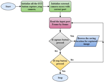
The transmitter and the receiver modules with their respective antennas are placed at a fixed distance D from each other. This handheld transmitter module with battery can move anywhere from the receiver module (with antenna) while varying the distance D up to 5 m with a step size of 0.5 m in different directions. A camera connected to the transmitter module captures real-time images, which are transmitted at a frequency of 5.8 GHz from the transmitter module. The signals are received by the receiver module and processed to give two analog output ports. To de-embed the images in any laptop or desktop computer, an audio/video to USB converter module was used. A stand-alone GUI application is developed to take the picture or image; Figure 2 depicts the operational flow chart. The BRISQUE method is created in Python code to assess the quality of the acquired picture [Reference Mittal and Bovik37]. This BRISQUE method maps the combined data into a numerical value, which is known as the image quality score (IQS) and its value varies from 0 (very good quality) to 100 (very bad quality).
Flowchart of graphical user interface (GUI) for image capturing.
The experiment setup is realized by using transmitter model TS832 audio/video, receiver model RC832 audio/video, a pair of standard dipole antennas, camera model Run Cam Nano 4, and batteries for 12 V DC. These models can transmit/receive the frequency-modulated carrier frequencies in the frequency range (FR)1 band of 5G communication.
Use of BRISQUE method
To evaluate image quality, most of the assessment techniques require a reference image and first, these techniques analyze image structure and identify patterns among its features. However, the BRISQUE method is considered particularly effective as it uses image pixel information to calculate these features [Reference Mittal and Bovik37, Reference Chawdhary, Kumari, Bhavsar and Verma38]. Along with the pairwise product coefficients, the design of the BRISQUE-based model takes into account the NSS of locally normalized brightness coefficients in the spatial domain. The process model, shown in Fig. 3, is developed taking these considerations into account.
Process model of the BRISQUE method used in this work.

The initial step involves subtracting the local mean from the image to obtain locally normalized luminescence, which is then divided by the local deviation. To prevent division by zero, a constant is included. Before computing the mean subtracted contrast normalized (MSCN) coefficients for a grayscale image, it is necessary to first calculate the local mean. The intensity value of the pixel I (i, j) is given by Eq. (1) as
 \begin{equation}{{\skew6\hat I}}\left( {{\text{i,}}\;{\text{j}}} \right){\text{ }} = \frac{{{\text{I}}\left( {{\text{i}},{\text{j}}} \right) - {{\mu }}\left( {{\text{i}},{\text{j}}} \right)}}{{{{\sigma }}\left( {{\text{i}},{\text{j}}} \right) + {\text{C}}}}\end{equation}
where i ∈ 1, 2 … M, j ∈ 1, 2 … N are spatial indices, M and N represent the height and width of the image, respectively. As the denominator gets closer to zero, a constant value of C = 1 is used to prevent any instability problems. The terms µ(i, j) and σ(i, j) present the local mean of the pixel’s neighborhood and the local standard deviation of the same neighborhood, respectively, and obtained using Eqs. (2) and (3) as follows.
 \begin{equation}{{\mu }}\left( {{\text{i,}}\;{\text{j}}} \right) = \mathop \sum \limits_{{\text{k}} = - {\text{K}}}^{\text{K}} \mathop \sum \limits_{{\text{l}} = - {\text{L}}}^{\text{L}} {{\text{w}}_{{\text{k}},{\text{l}}}}{{\text{I}}_{{\text{k}},{\text{l}}}}\left( {{\text{i}},{\text{j}}} \right)\end{equation}
 \begin{equation}\sigma \left( {{\text{i,}}\;{\text{j}}} \right){\text{ }} = \sqrt {\mathop \sum \limits_{{\text{k}} = - {\text{K}}}^{\text{K}} \mathop \sum \limits_{{\text{l}} = - {\text{L}}}^{\text{L}} {{\text{w}}_{{\text{k}},{\text{l}}}}{{\text{I}}_{{\text{k}},{\text{l}}}}\left( {{\text{i}},{\text{j}}} \right)} \end{equation}
where  $w = {\text{ }}\left\{ {w{\text{ }}k,l,k = {\text{ }} - K,{\text{ }}.{\text{ }}.{\text{ }}.,{\text{ }}K,{\text{ }}l = {\text{ }} - L,{\text{ }}.{\text{ }}.{\text{ }}.{\text{ }}L} \right\}$ is the implementation employs a circularly symmetric 2D Gaussian weighting function, sampled up to 3 standard deviations and adjusted to have a unit volume. In this case, K and L, which stand for the dimensions of the square window centered on the pixel of interest, are set to 3. The window size is an adjustable parameter that can be set based on the specific use case and the properties of the image.
The pixel’s contrast about its immediate neighborhood is represented by the resulting MSCN value, where positive values denote a higher contrast than the mean and negative values represent a lower contrast than the mean. The existence of distortion can affect the distinctive statistical characteristics of MSCN coefficients. By analyzing the changes in the statistical characteristics of an image, one can predict the effect of distortion on the image and its perceived quality. The MSCN coefficients are distributed as a GGD. The density function of the GGD is,
 \begin{equation}f\left( {x;a,{{{\sigma }}^2}} \right) = \frac{a}{{2\beta \Gamma \left( {\frac{1}{a}} \right)}}\exp \left( { - {{\left( {\frac{{\left| x \right|}}{\beta }} \right)}^a}} \right)\end{equation}
 \begin{equation}\beta = \sigma \sqrt {\frac{{\Gamma \left( {1/a} \right)}}{{\Gamma \left( {3/a} \right)}}} \end{equation}
where β is the parameter that affects the shape of the distribution and Г is the gamma function. The parameter α controls the form and σ 2 is the variance. Pairwise products of neighboring MSCN coefficients along four directions (1) horizontal H, (2) vertical V, (3) main-diagonal D1, and (4) secondary-diagonal D2 are considered and obtained using Eq. (6)–Eq. (9) as
 \begin{equation}H\left( {i,j} \right) = {{\skew6\hat I}}\left( {i,j} \right){{\skew6\hat I}}\left( {i,j + 1} \right)\end{equation}
 \begin{equation}V\left( {i,j} \right) = {{\skew6\hat I}}\left( {i,j} \right){{\skew6\hat I}}\left( {i + 1,j} \right)\end{equation}
 \begin{equation}D2\left( {i,j} \right) = {{\skew6\hat I}}\left( {i,j} \right)\;{{\skew6\hat I}}\left( {i + 1,j - 1} \right)\end{equation}
 \begin{equation}D2\left( {i,j} \right) = {{\skew6\hat I}}\left( {i,j} \right)\;{{\skew6\hat I}}\left( {i + 1,j - 1} \right)\end{equation}
Since GGD does not fit the empirical histograms of coefficient products well. Therefore, the model is fitted to asymmetric generalized Gaussian distribution. Its density function is given as,
 \begin{equation}f\left( {x;a,{{\sigma }}_l^2{{\sigma }}_r^2} \right) = \left\{ {\begin{array}{*{20}{c}}
{\frac{v}{{\left( {{\beta _l} + {\beta _r}} \right)\Gamma \left( {\frac{1}{v}} \right)}}\exp \left( { - {{\left( {\frac{{ - x}}{{{\beta _l}}}} \right)}^v}} \right),\,\,x \lt 0} \\
{\frac{v}{{\left( {{\beta _l} + {\beta _r}} \right)\Gamma \left( {\frac{1}{v}} \right)}}\exp \left( { - {{\left( {\frac{x}{{{\beta _l}}}} \right)}^v}} \right),\,\,x \geq 0}
\end{array}} \right.\end{equation}
As the BRISQUE approach performs well in real time, is very accurate, and does not require reference images, it is the method preferred for assessing image quality. Equations (1–10) are used to develop a Python code.
Image capturing
Antennas used in the experiments
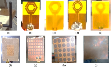
Four different antennas are employed as seen in Fig. 4, to assess the best antenna preferred for the intended image transfer application. Table 1 lists each antenna’s attributes.
(a) Dipole antenna, (b) front and (c) back side H-SRR antenna, (d) front and (e) backside C-SRR antenna, (f) front and (g) backside metamaterial (double negative index) Tx antenna, (h) front and (i) backside metamaterial (epsilon near zero) Rx antenna.
Different antennas and their features

C-SRR and H-SRR structures are a Mu-negative type of metamaterial and these structures act like an LC resonance circuit. When such a structure is used in place of a patch in a microstrip antenna [Reference Sehgal and Patel49], it radiates the same resonance frequency with a moderate gain and bandwidth. The resonance or radiated frequency is defined by the physical dimensions of SRRs and the gain between them [Reference Sehgal and Patel50]. A three-layer metamaterial Tx antenna consists of the complementary SRR on the top patch layer, microstrip feed on the middle layer, and grid patterns on the bottom layer and is a type of a double-negative metamaterial which gives wideband and high gain [Reference Yılmaz and Yaman51], whereas a three-layer metamaterial Rx antenna is made up of three layers: a middle layer of air, a top layer with circular patches etched from the Cu layer as the epsilon near zero layer, and a bottom layer with a rectangular patch of inset-fed microstrip with parasitic elements. It is designed for very high gain with a narrow beam at 5.8 GHz.
Experimental setup for image capturing
Four setups are considered in this study to perform the image transfer as shown in Fig. 4. In these setups, the receiver with antenna is placed in a laboratory on the ground floor of the building, whereas the transmitter with antenna is placed at different locations. In Setup 1, the transmitter is placed horizontally inside the same lab with a varying distance from 0 to 5 m with a step size of 0.5 m (Fig. 5(a)), while in Setup 2 (Fig. 5(b)), the transmitter is placed vertically inside the same lab with a varying 0 to 5 m with step size 0.5 m. In other setups, the transmitter is placed in different locations on the ground floor in the same building (Setup 3) which is represented by flag icons in Fig. 5(c), and the transmitter is placed in different locations on the first floor in the building (Setup 4) represented by flag icons in Fig. 5(d).
Image transfer using dipole antennas placed in (a) horizontal setup (Setup1), (b) vertical setup (Setup2), (c) ground floor (Setup3), and (d) first floor (Setup4).
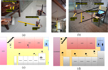
First, a pair of dipole antennas are used in all mentioned four setups as shown in Fig. 5(a) and (b), and images are captured, transferred and processed for IQA. In the same manner, a pair of H-SRR antennas and C-SRR antennas and metamaterial Tx and Rx (MMTR) antennas are used to transfer the images using Setup1 and Setup 3, which are illustrated in Fig. 6.
Setup 1 using (a) H-SRR antennas, (b) C-SRR antennas, and (c) metamaterial Tx and Rx antennas.
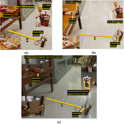
Image capture GUI app
Python programing has been used to create a GUI, as seen in Fig. 7. This application is capable of capturing images. It is completely a stand-alone application that doesn’t require any Python-oriented platform for its functioning. Given the way the developed programing, the user can only select steps to be performed by tapping the buttons on the application. First, double-click on the app icon to start, and a new graphical window will open if the receiver end is already connected to the laptop port, we can see the visuals in the webcam feed sub-window, for capturing the image by pressing the capture button and specify the path by browsing option and we can check the image saved or not using image preview sub window by browsing image.
Graphical user interface (GUI) for image capturing.

Results and analysis
As stated earlier, all four antennas are used in the experiments to capture a huge number of photos at various distances and locations. To keep the text concise, some of these photos have been chosen to be shown here. To give a thorough grasp of the picture capture performance, each of these selected photographs is assessed in conjunction with the associated IQS for the particular antenna that was used.
Images transferred using a pair of dipole antennas
The image taken in Setup 2 at a distanc of 1 m is shown in Fig. 8, and it has the lowest IQS score of 37.97 out of the four images and is of the highest quality. However, Setups 3 and 4’s IQSs of 41.68 and 40.90 demonstrate that the proposed wireless image transfer scheme works regardless of obstructions and orientations.
IQS of images transferred using a pair of dipole antennas for different setups.

Comparing the effectiveness of different antennas for image transfer
Experiments are carried out using three additional antennas for each of the two setups, Setup 1 and Setup 3, to determine which antenna set is best for the suggested application. For these configurations, the images with their IQS acquired are displayed in Figs. 9 and 10, respectively.
Comparison of IQSs of images for Setup 1.

Comparison of IQSs of images for Setup 3.

On observing Fig. 9, it is noted that Setup1 with dipole antennas offers the best IQS value of 46.390 than other antennas up to 1 m of distance. For larger distances of 2 and 3 m, the use of MMTR antennas provides IQS values of 42.065 and 40.231, respectively. Figure 10 shows the images and their IQS values obtained in Setup 3. The lowest value of IQS obtained using MMTR antennas confirms that the higher gain antennas with narrow beamwidth (Table 1) are best for wireless image transfer. The higher gain of both three-layer metamaterial antennas with good bandwidth and narrow beam width led to more efficient radiated power transmission and focused reception, which improved the signal transmission/reception than the C-SRR and H-SRR antennas. So, the use of MMTR antennas offered good quality image transfer and a longer range. Additionally, IQS values are thoroughly assessed for every image utilizing each of the four antenna sets, and the results are shown in Fig. 11. Using Eq. (11) to estimate the variance in IQS values, performances can be evaluated efficiently against the standard dipole.
 \begin{align} {\rm IQS\ deviation} \left( {\Delta} \right) & = {\rm IQS\ of\ different\ antennas}\nonumber \\ & \qquad - {\rm IQS\ of\ Dipole\ Antenna}\end{align}
According to Fig. 11(a), the IQS of the dipole antenna is lower than the IQS of the C-SRR antenna for distances up to 1.5 m and then becomes higher. So, the quality of images obtained using C-SRR antennas is better after these distances. Notably, the IQS of the C-SRR antenna remained relatively constant as the distance between the transmitter and receiver was further increased. Given that Table 1’s antenna characteristics are the same for both C-SRR and H-SRR antennas, it can be observed in Fig. 11(b) that the IQS of the H-SRR antenna is comparable to those generated from C-SRR antennas. Again, as in Fig. 11(c), the IQS of the dipole antenna is about 48 and much better than that of the metamaterial (MMTR) antennas for distances up to 1.5 m. After this range, the metamaterial antennas exhibited further lower values of IQS, which shows that the quality of images gradually enhanced with longer distances while the performance of C-SRR and H-SRR is nearly constant at the same distance. Figure 11(d) shows the IQS deviation (Δ) of different antennas with respect to the dipole antenna. The IQS deviation of the C-SRR and H-SRR antenna is negative for most of the distance, it implies that C-SRR and H-SRR are better than dipole antenna. The IQS deviation of metamaterial antennas is found to be more positive as compared to the other two SRR antennas up to 1.5 m, which implies that the use of metamaterial antennas is unsuitable for very small or close distances. However, after 2 m, the deviation becomes negative and further negative with distance increases, which confirms the image quality is becoming better using these antennas for longer distances.
Comparison of image quality score for Setup 1: (a) dipole and C-SRR antennas, (b) dipole and H-SRR antennas, (c) dipole and metamaterial antennas, and (d) IQS deviation with respect to dipole antenna.

To further validate the comparison, images taken at the same locations using four antennas in Setup3 are analyzed and IQS values are shown location-wise of Setup 3 in Fig. 12. Figure 12 confirms that the dipole and C-SRR antennas are providing higher values of IQS in the same floor of building while H-SRR and metamaterial antennas offer better IQS values. In addition, the IQS values obtained using H-SRR and metamaterial antennas remain almost constant and independent of the direction or distance of the transmitter from the receiver position, even though the metamaterial antennas are more directional. The results show that presented metamaterial antennas are best for the proposed application of wireless image transfer.
Comparison of IQS for Setup 3.

To show the novelty in the current research work a comparison with the previously published work is shown in Table 2. In comparison, most of the previous techniques involve complex processing and encryption algorithms to improve the quality of transmitted or encrypted images, whereas the proposed technique of wireless image transfer is a simple, cheaper, and faster technique that can be implemented with a laptop and a little signal processing. Most of the reported techniques are verified by simulation in various scenarios and modulations, the proposed technique is implemented physically and the quality of received or transferred images is assessed in terms of IQS.
Comparison of present work with previously published literature
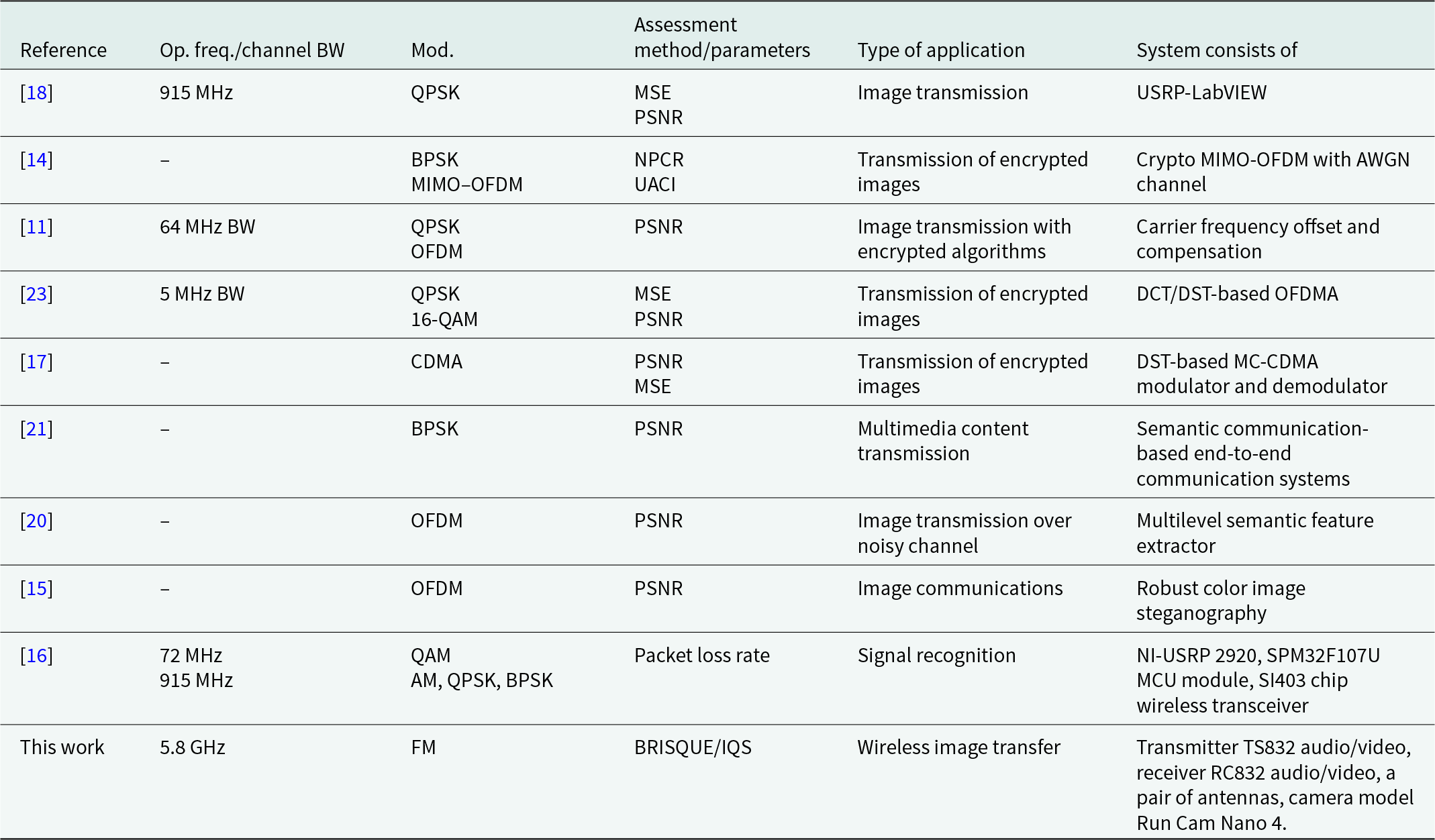
PSNR = peak signal-to-noise ratio; MSE = mean square error; SSIM = structure similarity index measure; IQS = image quality score; NPCR = number of changing pixel rate; UACI = unified averaged changed intensity.
Limitation and future scope
The real-time image quality can be improved further by optimization of antenna designs, including metamaterial antennas, and the use of advanced signal processing methods. These advanced signal processing algorithms are required to enhance image quality by noise reduction, and compression techniques, to minimize data loss during transmission. Also, the optimal deployment and positioning of antennas would maximize signal coverage and minimize signal attenuation, by considering factors such as antenna height, orientation, and spatial arrangement in the surveillance area. Also, in this work, a camera model RunCam Nano 4 is used to keep the proposed application cheaper and handy. By replacing it with a good quality camera, the quality of images can be improved directly. The limitation of the present work is the use of bulky and large-size MMTR antennas for better image quality. In addition to improving the image quality as mentioned in the response to previous comment 7, the new antenna design should focus on the compact high gain and narrow beam width antennas. Also, to increase the range of transmission/reception beyond 100 m, a similar analysis should be performed at a lower frequency like 3.5 GHz in the 5G FR1 band.
Conclusion
The present work demonstrated the performance of different antennas in real-time wireless image transfer for surveillance and security purposes using the 5.8 GHz transmitter and receiver commercial modules. The images are taken at different locations and distances from the receiver position. The IQS is obtained using the BRISQUE method and evaluated for all captured images. The results showed that, when it came to wireless image transfer, the metamaterial antenna outperformed any other antenna. Signal quality and intensity are much enhanced in the desired direction due to their directional emission pattern. These findings suggest that to achieve reliable and efficient wireless image transfer for security applications, antenna selection is essential. So, this is the first step for video streaming or video conferencing in real time and in short range without involving other services. In the future, the required modification will be explored to extend the range and quality of images.
Acknowledgements
The work is supported by the Faculty Research Programme (FRP) of the Institute of Eminence (IoE) scheme of the University of Delhi (Letter Ref./No./IoE/2021/12/FRP dated 31.08.2022).
Competing interests
The authors declare that they have no known competing financial interests or personal relationships that could have appeared to influence the work reported in this paper.

Kamlesh Patel received his M.Sc. degree in Electronics and M.Tech degree in Microwave Electronics from Rani Durgavati Vishwavidyalaya, Jabalpur, India, and the University of Delhi, India, in 1999 and 2003, respectively. He holds Ph.D. from the Delhi Technological University, Delhi, India. From 2004 to 2013, he had worked as scientist with CSIR-National Physical Laboratory, India. Since 2013, he has been working with the Department of Electronic Science, University of Delhi South Campus, New Delhi, India, where he is now an associate professor. His research interests include microwave components, material characterization, and planar antennas for mobile communications.

Gobind Rai received B.Sc. degree in Electronics Science from Maharaja Agrasen College, which is affiliated with Delhi University (DU), Delhi 110096, India, in 2021, and an M.Sc. degree in Electronics from the Department of Electronic Science, University of Delhi, South Campus, New Delhi, India, in 2023.

Puneet Sehgal received his B.Sc. (Hons.) and M.Sc. degree in Electronics from University of Delhi, India, in 2009 & 2011 respectively. He is currently pursuing Ph.D. degree (Electronics) with Department of Electronic Science, University of Delhi (South Campus), New Delhi. He is currently working as an assistant professor in Department of Electronics, Atma Ram Sanatan Dharma College, University of Delhi.



